
Description
Bathymetry
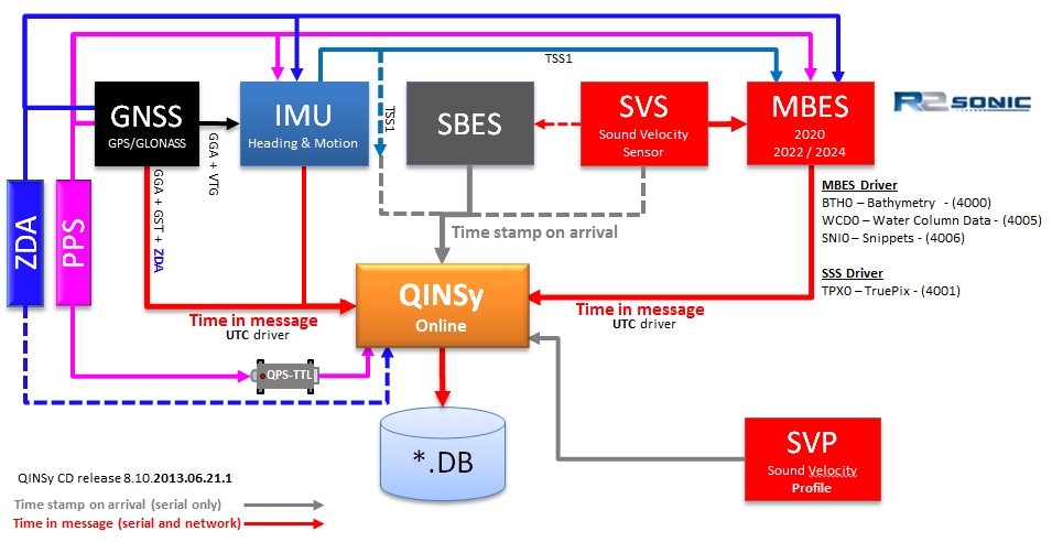
Driver for R2Sonic 2000 series Multibeam Echosounders using a network connection (UDP).
The driver will decode the BTH0 Bathymetry format but for backward compatibility it will still decode the Reson 8000 series bathymetry packets.
Make sure that the R2Sonic sounder is set up to output the Bathymetry (BTH0 packet).
Snippets
The multibeam driver can read the snippet data (SNI0 packets) as part of the Multibeam system. The snippets can also be shown in a sidescan display.
Qinsy can optionally store the raw snippet data depending on the settings in Database Setup.
Water Column Data
The multibeam driver can also read and decode WCD0 water column data messages.
Tip
There are two types of Water Column Data packets: Magnitude only and Magnitude and Phase. The first will induce a data output rate of 30 MB/second and the last an output rate of 70 MB/second. We currently advise to use Magnitude only to save disk space.
If you would like to store the WCD data in a database make sure that your hard disk is fast enough and even consider buying a Solid State Disk (SSD).
If you would only like to see the imagery in a raw display then you can just disable the water column storage in the Controller's Session Setup.
Please read the NicSetupForWaterColumnData.pdf (R2Sonic document) on Network Throttling.
TruePix
The Side Scan Sonar driver can decode the TruePix messages (TPX0 packets, as from Qinsy CD version 8.10.2012.05.06.1) and show them as sidescan data. It is also possible to log the raw TruePix messages in the Database.
TruePix
A Side Scan Add-on is required to record and display TruePix.
TruePix can be processed as Sidescan data by
|
R2Sonic 2026 |
R2Sonic 2024 |
R2Sonic 2022 |
R2Sonic 2020 |
|---|---|---|---|
|
|
|
|
|
Driver Information
|
Driver |
R2Sonic 2000 Series (Network) |
Interface Type |
UDP |
Driver Class Type |
|
|---|---|---|---|---|---|
|
Yes |
Input / Output |
Input |
Executable |
DrvR2Sonic.exe |
|
|
Related Systems |
|||||
|
Related Pages |
|
||||
Decoding Notes
-
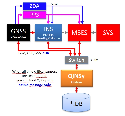
Timing
The time tag from the data packets is always decoded and used. Therefore make sure that the R2Sonic System is fully time synchronized to UTC.
-
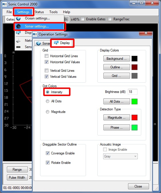
Intensity Beam Average
If the sending of Intensities is enabled in the R2Sonic 2000 control software (see picture below) then the driver will decode the Intensity Beam Average value as the backscatter value per beam which can be stored in a Sounding Grid layer (see Qinsy Online section).
|
Before |
From June 27th 2014 onward |
|---|---|
|
|
-
Received Beams
The reported beam angles are with respect to the face of the transducer.
-
Quality
No quality flags are available in the message, but one can distinguish valid detected beams from invalid beams by looking at the travel times: invalid beams will have a zero travel time and hence no range.
Note that older drivers decoded brightness and collinearity flags from the message but such filtering has never been implemented in the R2Sonic firmware. But as a side effect it was possible to block ranges with zero values this way.
For clarity's sake as of December 2012 the option to filter on these flags has been removed. You will have to set up a range or depth blocking to filter out the invalid detections.
-
Data decoded from packets
|
System Type |
Observation |
Unit |
|
|---|---|---|---|
|
1 |
MBES |
Ping number |
|
|
2 |
MBES |
Beam Count |
|
|
3 |
MBES |
Observation time |
|
|
4 |
MBES |
Sound Velocity |
m/s |
|
5 |
MBES |
Pulse Frequency |
Hz |
|
6 |
MBES |
Pulse Length |
Seconds |
|
7 |
MBES |
Ping rate |
Pings per second |
|
8 |
MBES |
Transmit power |
re 1 μPa at 1 meter [dB] |
|
9 |
MBES |
Transmit Beam width |
Degrees |
|
10 |
MBES |
Spreading |
Loss due to sound wave moving away from the source [dB] |
|
11 |
MBES |
Absorption |
Loss due to absorption by the medium [dB/km] |
|
12 |
|
|
|
System Configuration
Network setup
-
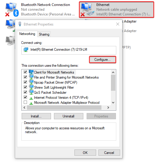
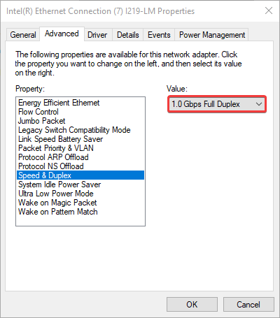
In order to make sure all the multibeam data is sent properly to the PC, R2Sonic suggests to set the following:
If you still run into receiving issues (packets being dropped) with the Water Column data we suggest to contact R2Sonic and ask for their "Network Interface Controller Setup of Water Column Data".
-
You can find the network settings for the software itself here:
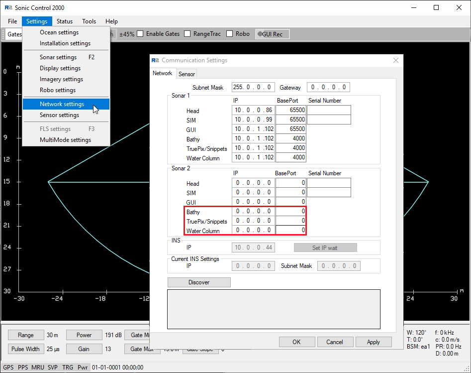
In case you want to distribute the MBES data to multiple PCs, you can set the last part of the IP address to 255.
Message output
-
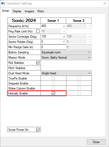
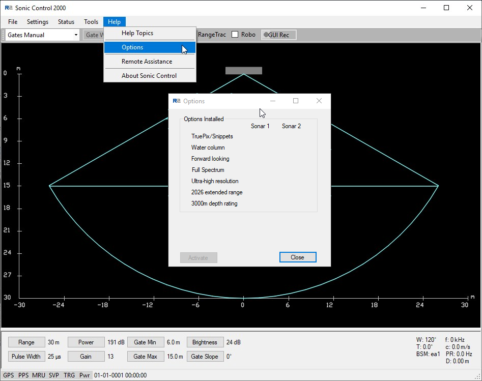
As of Sonic Control 2000, built June 27th, 2014, you can select the required output in the user interface and check the installed options:
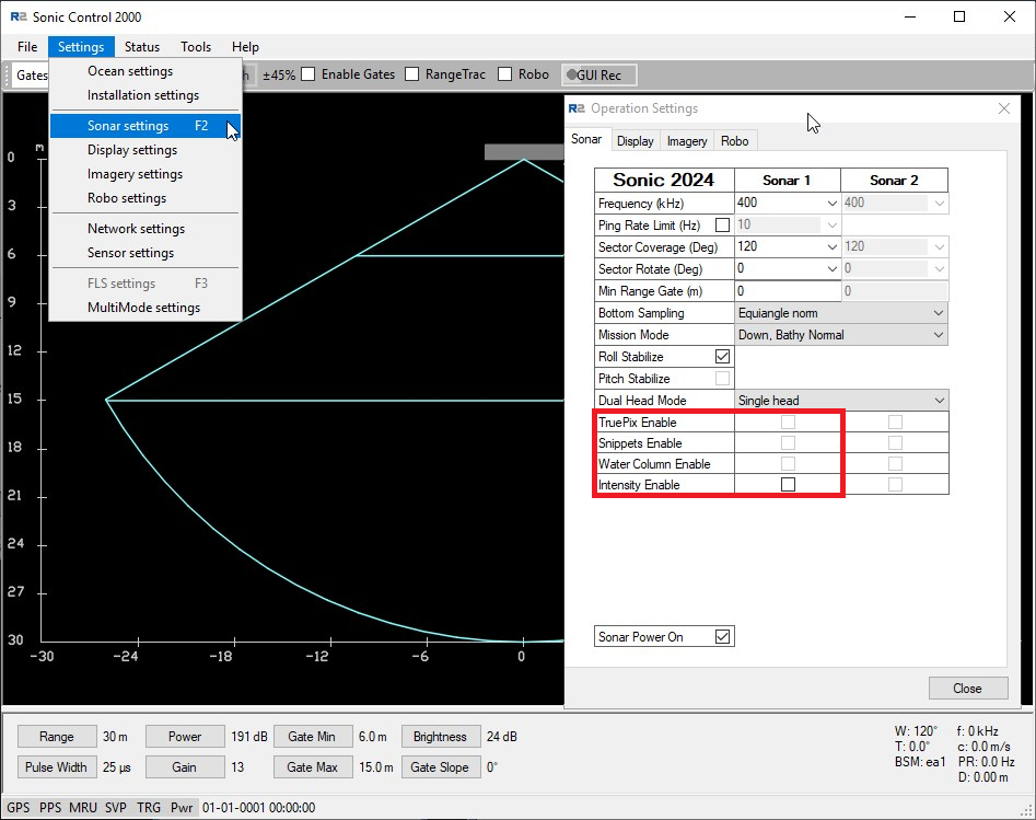
Port Setup in R2Sonic Control Program
Note that as of March 2013 the driver will automatically determine and open the actual UDP ports.
So make sure to set the output UDP Base port in the Sonic Control program to the same number (e.g. 4000) for every data type!
-
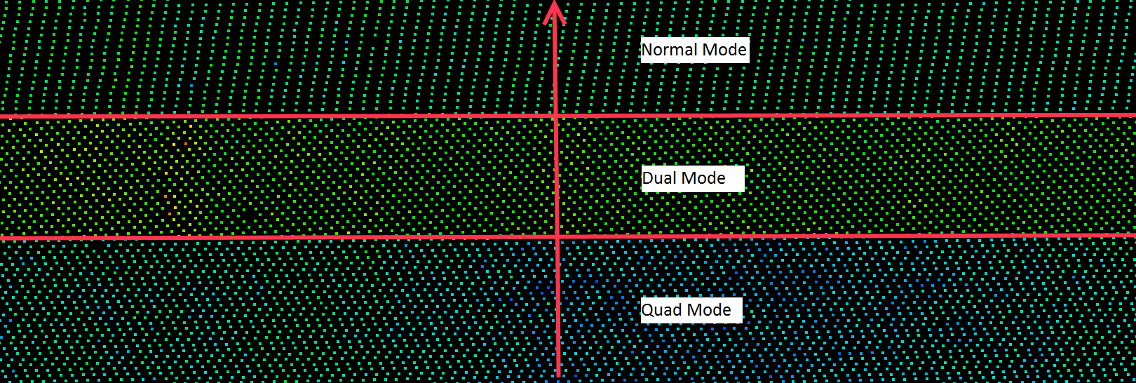
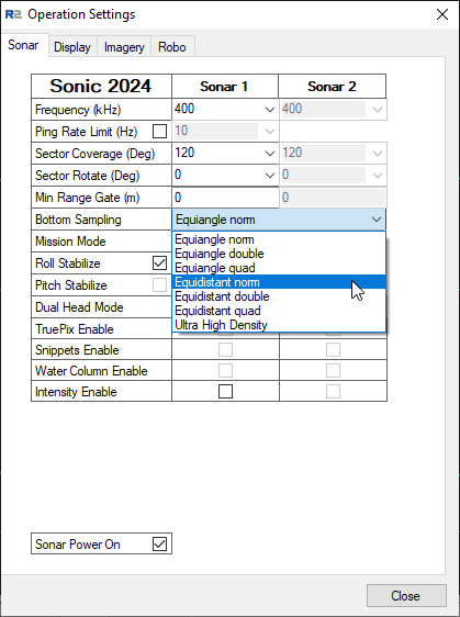
Density modes
R2Sonic multibeam echosounders have the possibility to increase the point density with different "Density Modes":
-
Normal mode
-
Dual Mode
-
Rotating swath, back and forth, with half a footprint every ping.
-
-
Quad Mode
-
Rotating swath, back and forth, with a quarter of a footprint every ping.
-
-
Ultra High Density (UHD)
-
This gives you 1024 soundings.
-
Page 53 of the R2Sonic 2024/2022 Operation Manual v5.0 Revision 002 contains a more detailed description of this option.
-
-
Truepix
In case you would like to store Truepix, which you would like to use as WaterComlumn-like data in Qimera, you will need to set the following: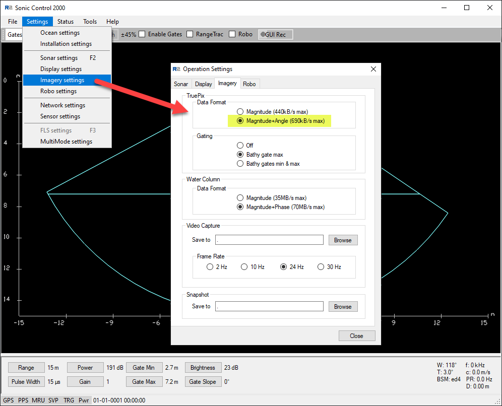
Interfacing Example:
Database Setup
Setup for XTF files
If you would like to record the raw data packets for the purpose of XTF export later or for XTF file creation online, then please select the appropriate Driver Specific Settings in Database Setup (see below).
This applies to both multibeam and side scan systems.
-
Multibeam Echosounder
Add a new Multibeamer System, select driver "R2Sonic 2000 Series (Network)".
Select port number identical to the output port that is set up in the R2Sonic 2000 control program. (See menu Settings|Network|Data acq PC.)
The default port is 4000, this is also called the "Base port". In case of a dual head system two instances of the system need to be defined.
The default port for the second head is 5000. Note that in both cases (single or dual head system) the driver will automatically open the correct ports for snippets (Base Port + 6) and water column data (Base port + 5).-
Edit System

The default port number for an R2Sonic is 4000. Note that some messages like snippets and watercolumn are sent on different port numbers (see R2Sonic documentation) and the driver takes care of this.
The checkbox at the left bottom can be checked if you want to enable control of the Head from Qinsy:-
Range
-
Trigger mode
In most survey operations you will use the Sonic Control 2000 software to control the head.
This option was added for AUV operations. Contact QPS Support if you need to know more.
-
-
Driver Specific Parameters
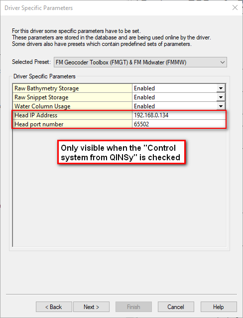
In Database Setup for this driver some driver specific settings can be entered.
These supersede the command line parameters and XTF options that were used in the past.The following settings can be selected for the Multibeam system:
-
|
Setting |
Option (bold=default) |
Description |
|---|---|---|
|
Raw Bathymetry Storage |
Disabled |
Only the decoded (raw) multibeam data is stored. Online the data can be used to fill a navigation grid and it can be viewed in a Raw Multibeam Display and a Swath Display. |
|
Enabled |
Both the decoded (raw) multibeam data and the original Raw Bathymetry packets (e.g. BTH0) are stored in the database for usage in Fledermaus and Export to 3rd party formats like XTF. |
|
|
Raw Snippet Storage |
Disabled |
SNP0 messages are not decoded and not stored in the Qinsy *.DB files. |
|
Enabled |
The Snippet message (SNP0) is stored in the database. Online the data can be viewed in a Raw Multibeam Display and it can be used to fill a sounding grid on the fly. As it was In the past Snippet data was stored as part of the Sidescan system data but this is now part of the Multibeam data.
|
|
|
Water Column Usage |
Disabled |
No WCD data can be displayed in the Raw Multibeam Display. |
|
Enabled |
The WCD is decoded by the Driver and can be displayed in the Raw Multibeam Display.
|
If you would like to use the Water Column Data then make sure that the setting "Water Column Usage" is set to "Enabled".
If the R2Sonic outputs WCD0 messages this will make sure that they are decoded.
|
Head IP Address |
This is the IP address of the Head which can also be found in the "Network Settings" of the R2Sonic GUI. |
|---|---|
|
Head port number |
This port number can also be found in the GUI and the default is 65500. Note that in Qinsy you need to add 2 so in this example 65502. |
c. Multibeam Echosounder Parameters
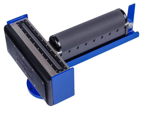
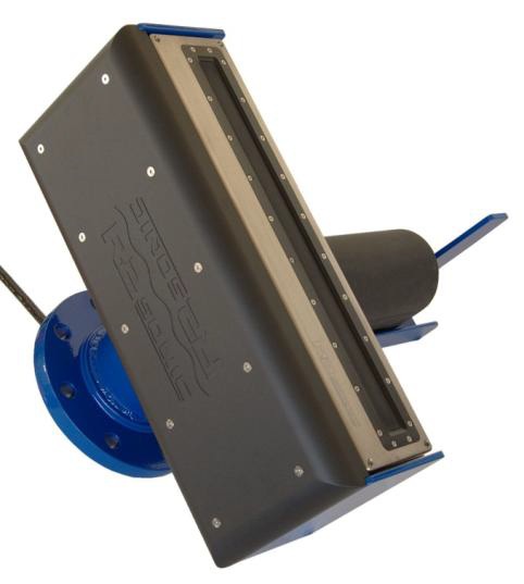
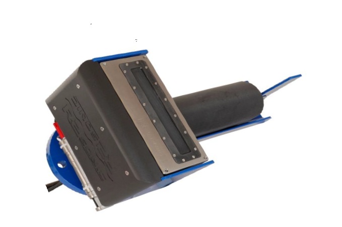
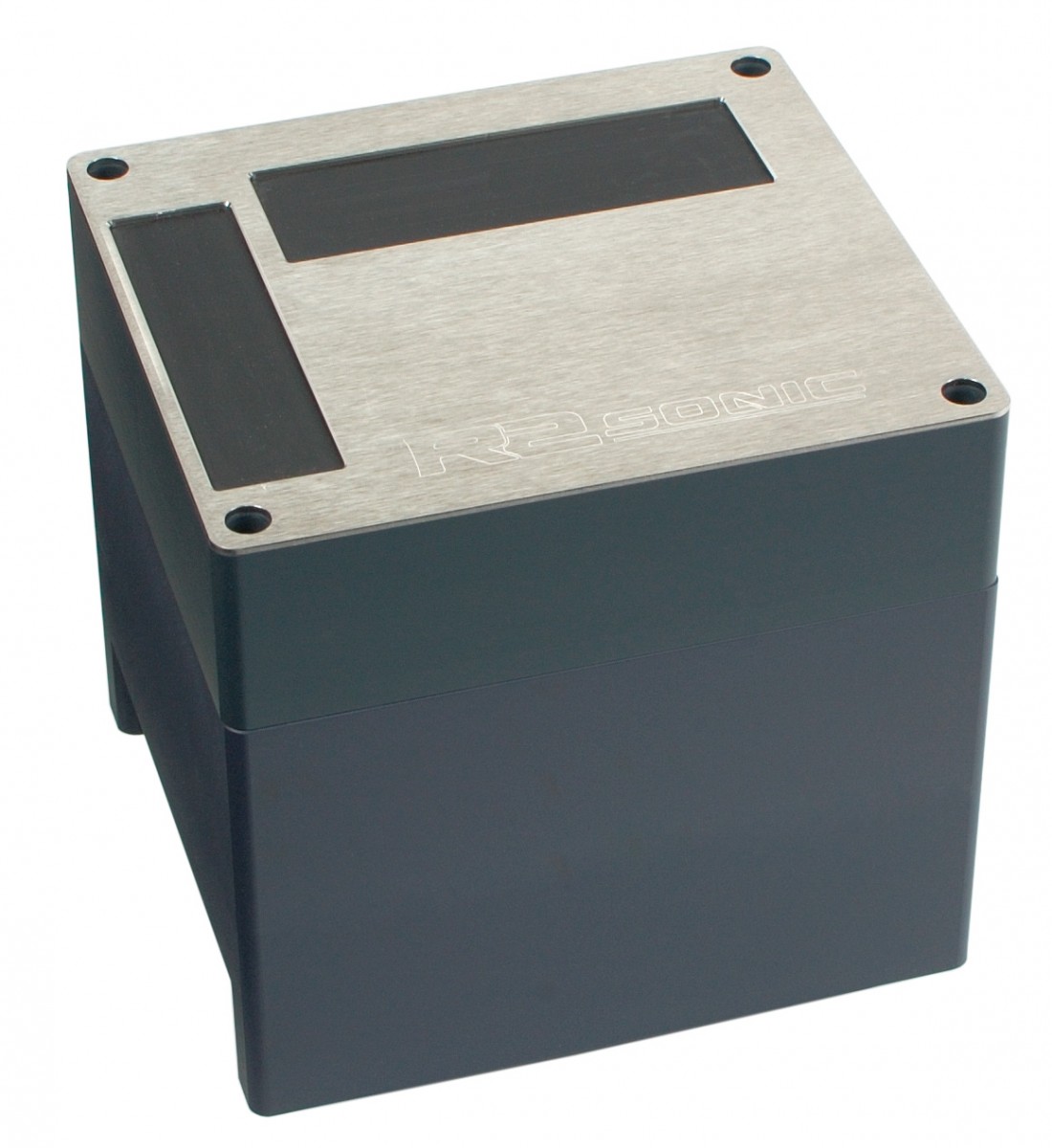
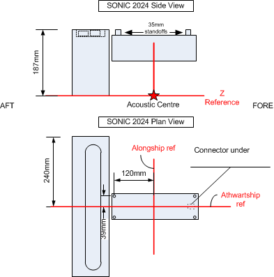
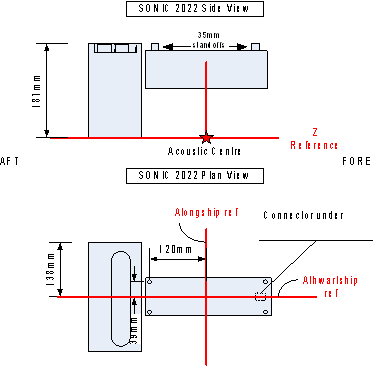
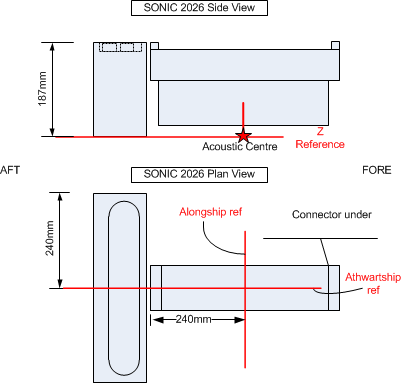
Transducer Setup
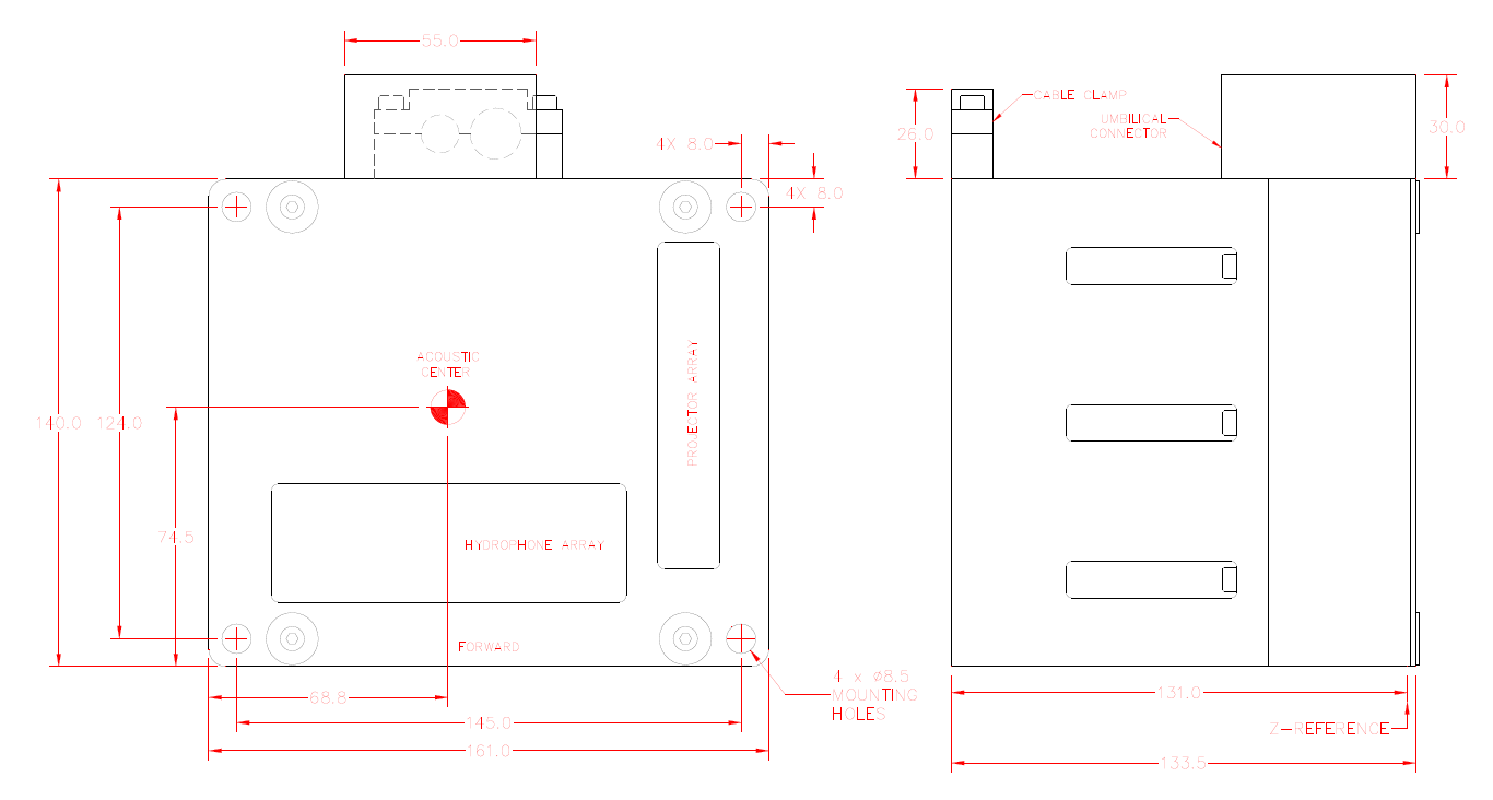
Always set the "Transducer Setup" to "Assume Common Acoustic Center".
For the acoustic center definition refer to the figures below. Note that the Projector Z offset needs to entered in the R2Sonic GUI.
Non-standard mountings are described in the R2Sonic manual which can be accessed in the R2Sonic GUI through the Help menu.
Non-standard mountings also use the Assume Common Acoustic Center setting.
|
R2Sonic 2024 |
R2Sonic 2022 |
|---|---|
|
|
|
R2Sonic 2026 |
R2Sonic 2020 |
|
|
Max. Beam per ping
Depending on the firmware version the R2Sonic delivers 256 or 1024 beams per ping so the "Max. beams per ping" value should be 256 or 1024.
Sound Velocity
Since the surface sound velocity sensor is fed straight into the sonar Qinsy doesn't need to recalculate the Beam Angles.
Sound Velocity Profile
SVP can be entered/imported/selected during Online/Replay.
Echosounder Stabilization
The R2Sonic will always report its used beam angles relative to the Multibeam local frame, so Qinsy will always be able to calculate the correct footprints whether the stabilization features of the sounder are used or not.
Nor will the option equidistant have a negative effect due to relative beam angles reported.
Echosounder Accuracy Parameters
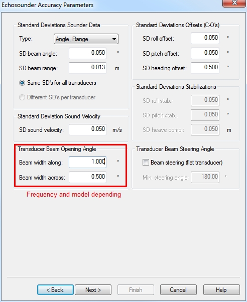
The settings above are model and frequency (2020 / 2022 / 2024) dependent. Check the R2Sonic documentation for related parameter information.
The parameters above are used for calculating Total Propagated Uncertainties (TPU), which are used for filtering (IHO-S44, IMCA, NL-NORM, CUBE, QPS Spline filters).
Multibeam Echosounder Corrections
On the page, Multibeam Echosounder Corrections, you could select sensors that would be used for adjustable alignments of the multibeam installation.
Some vessels can rotate the multibeam for quay wall / jetty / breakwater inspections.
Related Systems
When finishing the setup wizard you will be prompted by a dialog that will offer you the option to install other systems that use the same driver executable:
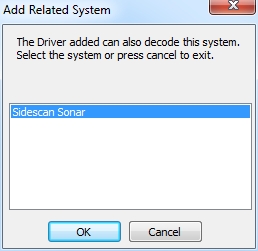
When you click on OK a new wizard will be started to set up the related Sidescan Sonar system.
-
Sidescan Sonar (TruePix)
For TruePix decoding:
-
New System
If you cancelled the prompted additional driver wizard mentioned above you have two options:-
Right click with your mouse on the MBES system you have set up and select the related Sidescan Sonar driver:
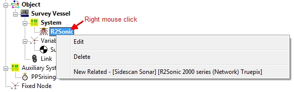
Driver type, Driver, Port number and IP are already selected for you and correspond with the related MBES driver
-
Manually add a Sidescan Sonar (SSS) system
-
Select driver "R2Sonic 2000 Series (Network) TruePix",
-
Select port number identical to the output port that is set up in the R2Sonic 2000 control program. The default port is 4000, this is also called the "Base port".
In case of a dual head system two instances of the system need to be defined. The default port for the second head is 5000.
Note that in both cases (single or dual head system) the driver will automatically open the correct ports for TruePix (Base port + 1).
-
-
-
Driver Specific Parameters
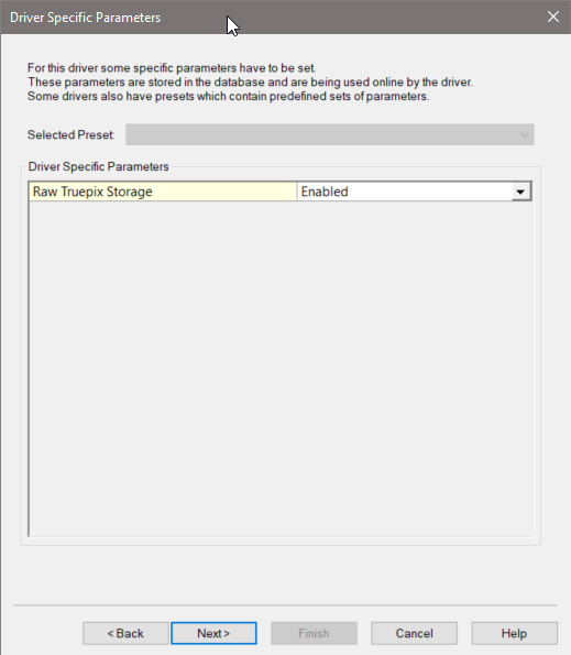
The following settings can be selected for the Sidescan Sonar system:
-
|
Setting |
Option (bold=default) |
Description |
|---|---|---|
|
Raw TruePix Storage* |
Disabled |
TruePix will be decoded as a Sidescan Sonar system and stored as sidescan data. Online the decoded side sidescan data will be displayed in a Sidescan Display |
|
Enabled |
The Raw (original) TruePix packets (e.g. TPX0) are stored alongside the decoded sidescan data in the database.
Use the following settings to export the TruePix to XTF in Replay (Raw Data Manager) - Export - XTF: 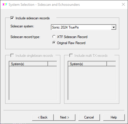
XTF
|
c. Sidescan Sonar General Parameters
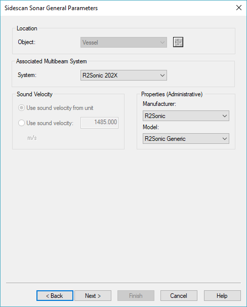
Object - Select the same object as you have selected for the related MBES driver and select the associated MBES system.
d. Sidescan Sonar Channel Setup
Add a Port side and Starboard channel (read more about SSS systems in: 'How-to Sidescan Sonar' in the Qinsy Knowledge Base).
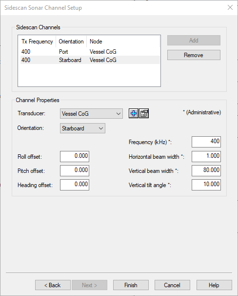
Please note: There is no XTF ID available yet in the XTF description for TruePix at the moment of writing.
Time Synchronization System (previously PPS)
Read more about timing in Qinsy in the Drivers Manual and the Qinsy Knowledge Base:
-
Drivers Manual:
-
Time Synchronization Drivers
-
-
Knowledge Base:
-
How-to Timing in Qinsy
-
How-to Time Synchronization Display
-
Qinsy Online
Tip
In the Knowledge Base you can find a document named 'How-to Create XTF'.
Control unit from Qinsy
If you enabled the 'Control unit from Qinsy' checkbox in the template setup (see Database Setup part of this manual) you will be able to send some simple commands to the R2Sonic.
The Control options can be found in the Echosounder / Multibeam Settings.
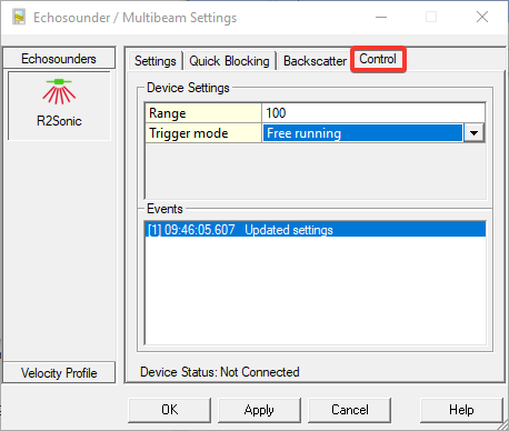
Range
This is the range in which the R2Sonic tries to detect the bottom. Try to keep the range the same as the slant-range of the outer beams.
Trigger mode
|
Free running |
Device will try to ping as fast as possible |
|---|---|
|
External trigger on SIM |
An external input to the SIM is used to trigger a ping |
|
Standy on PGN0 command |
Manual ping. Each time this command is sent, sonar will emit one ping |
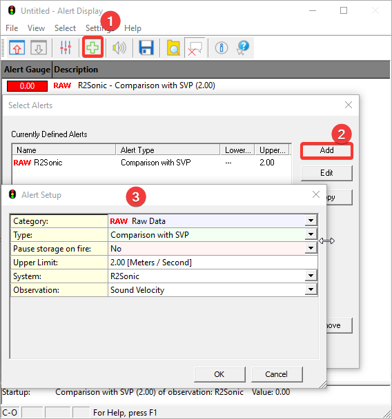
Sound Velocity
It is advised to check the Sound Velocity (SV) reported by the MBES against the Sound Velocity Profile (SVP) used during acquisition.
The SV reported by the MBES cannot be altered afterwards or during Replay.
An alert can be set to compare the SV against the SVP:
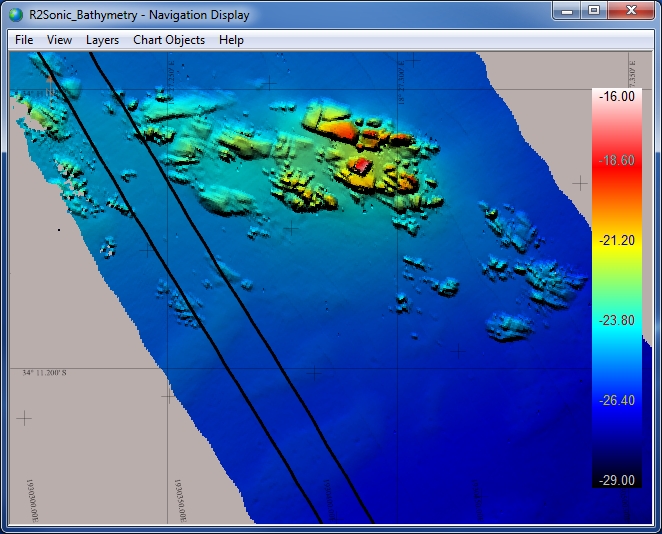
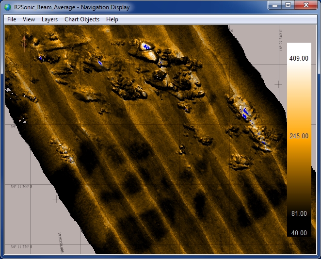
BTH0 - Intensity Beam Average
To be able to see the Per_Beam_Intensity one needs to use a Sounding Grid in the Session Setup:
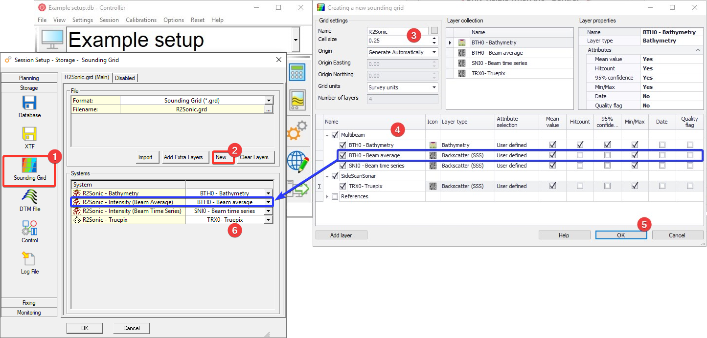
When using a layer of the type Sidescan, one will be able to use a different color table for the Intensity data:
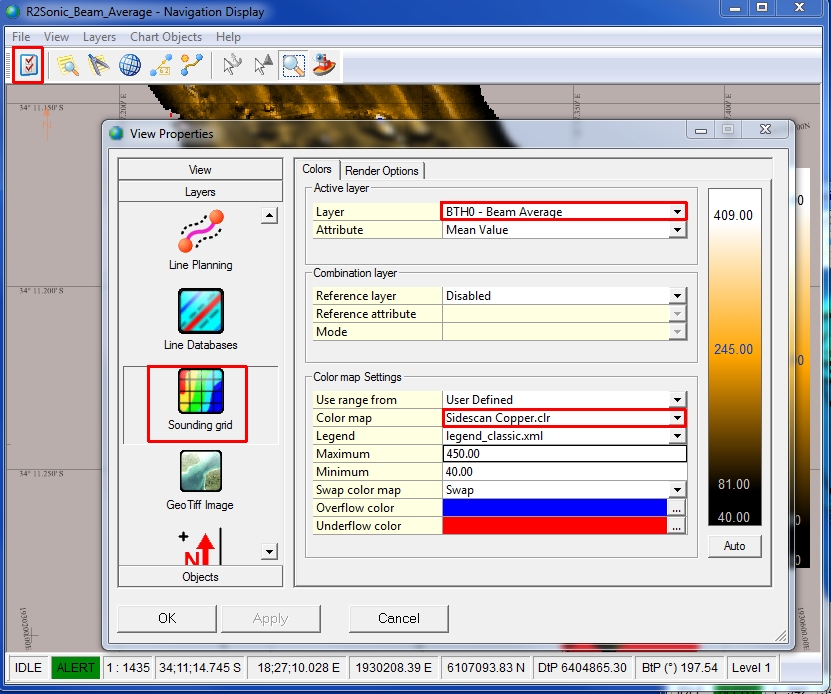
The layer needs to be selected in the Navigation Display to be able to see the (backscatter) layer with the BTH0 - Beam Average values:
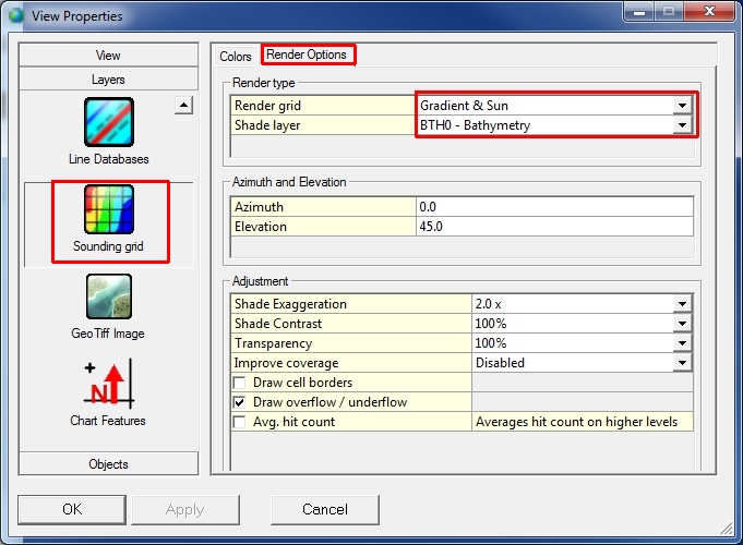
|
BTH0 - Bathymetry |
BTH0 - Intensity Beam Average |
|---|---|
|
Shade layer: BTH0 - Bathymetry |
Water Column Data
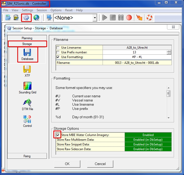
If you enabled the Raw Data for water column usage in Database Setup and you want to record the WCD0 data in the database, you can enable it in the Session Setup Dialog: Storage - Database options.
|
Online - Controller |
|---|
|
For more info on water column handling and processing, refer to the Knowledge Base article "How-to Water Column Data".
If the bathymetry data is not coming into Qinsy Online, please ensure that the ‘UDP Driver for R2Sonic Multibeam Systems’ app is allowed through your firewall for the specific version of Qinsy you are using!