
Making a new Sounding Grid
There are two primary places for creating a new sounding grid:
-
Controller - Settings - Session Setup - Storage - Sounding Grid: This is the best option for dredging. It uses the newer 'Creating a New Sounding Grid' program. At startup a number of predefined layers, based on the content of the template database, are available for activation.
-
Processing Manager - File - New - Sounding Grid: This option uses the previous sounding grid program. At startup only one layer is predefined. You have to add any others you want.
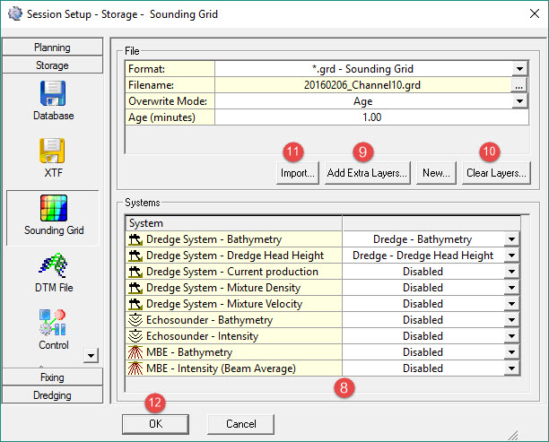
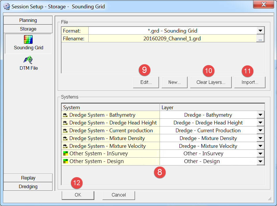
Controller - Settings - Session Setup - Storage - Sounding Grid

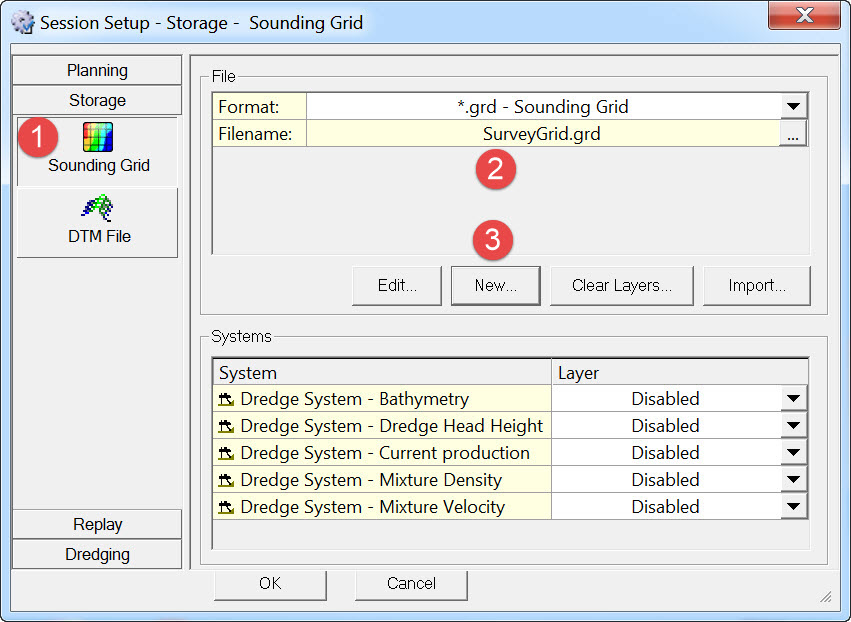


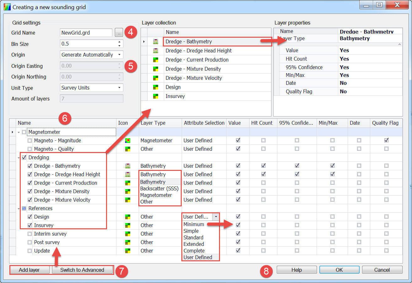


From the default tree list, tick the layers to be activated for this new sounding grid. Those layers are copied to the Layer Collection window.
Choose the Layer Type and Attribute Selection for each activated layer. The number of attribute boxes checked depends on which attribute level is selected.
For example, attribute Minimum checks only the Value tick box.
User Defined allows you to check whichever attributes you want.
As you highlight each layer in the Layer Collection window, its selected attributes are listed under Layer Properties.
The default names and layer types of the suggested layers can also be configured

A new layer called 'New' is created under the highlighted layer type.
Alternatively use the right click menu. Edit the name if necessary.
Click on Switch to Advance/Switch to Normal to change the layer listing.
Normal mode: By default the program provides a limited list of suggested layers based on the different types of systems detected in the template or replayed database.
Advanced: The program gives an extended list of suggested layers. All systems are detected in the template or replayed database.
This option is only available when creating a New sounding grid. It does not appear when the Edit button has been used.


The Add Layer button is live and any new layers added are editable in terms of layer type and attribute selections.
Grid Settings can be modified.


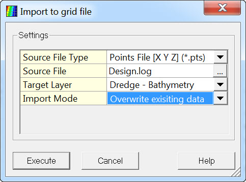
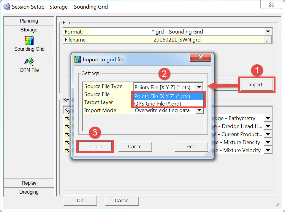
Source File Type: select either Points File or QPS Grid File.
Source File: browse to the required file.
Target Layer: all the previously defined layers are listed.
Import Mode: choose between Overwrite Existing Data and Merge with Existing Data.

Return to: top of page.
How to use the old sounding grid dialog instead of the Create Sounding Grid application
If preferred the older sounding grid program can be used.
It requires a registry setting change.
Open the Controller - Session Setup - Storage - Sounding Grid page once. Then close the Controller.
The registry key with default value is now added to the registry.
Open the registry settings by pressing the Windows key and typing Regedit in the search box.
-
In the Registry Editor, click Edit -> Find.
-
Fill in: Allow Legacy SoundingGridDialog.
-
Right-click on it, and select Modify.
-
Its default value is 0000 00.
-
To enable the new app, change it to 0000 01.
-
Click OK, close the Registry Editor.
|
Registry Setting Name |
Value |
Effect |
|---|---|---|
|
Allow Legacy SoundingGridDialog |
0000 00 |
Default. Create Sounding Grid application is used. |
|
Allow Legacy SoundingGridDialog |
0000 01 |
Old Controller dialog is used. |
Relaunch the Controller - Session Setup - Storage - Sounding Grid page.
The Edit button is now disabled since it can only be used with the Create Sounding Grid application.
The New button now launches the old dialog.
The former application is used by default when creating a new grid in the Processing Manager, and when using the stand-alone program, i.e. \Program Files (x86)\QPS\QINSy 8.1\SoundingGridUtility.exe.
Return to: top of page.
Processing Manager - File - New - Sounding Grid
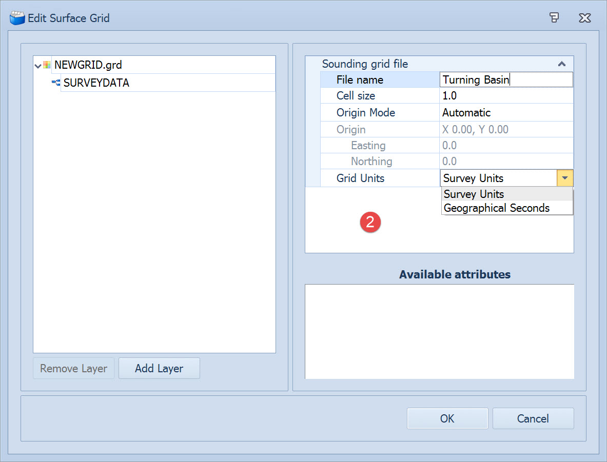
Cell size: Enter a value for the base Cell Size. (Reminder - an additional 5 grid layers are created with increasing cell size.)
Origin mode: Automatic centers the grid around the very first point that is imported or that is written to file during acquisition.
When a Grid is defined by geographical coordinates Latitude and Longitude be careful in setting the base cell size: 1 second of arc at 45 deg latitude is approximately 31m in latitude and 22m in longitude. If you want a geographical cell size equivalent to 1 meter enter 0.03".
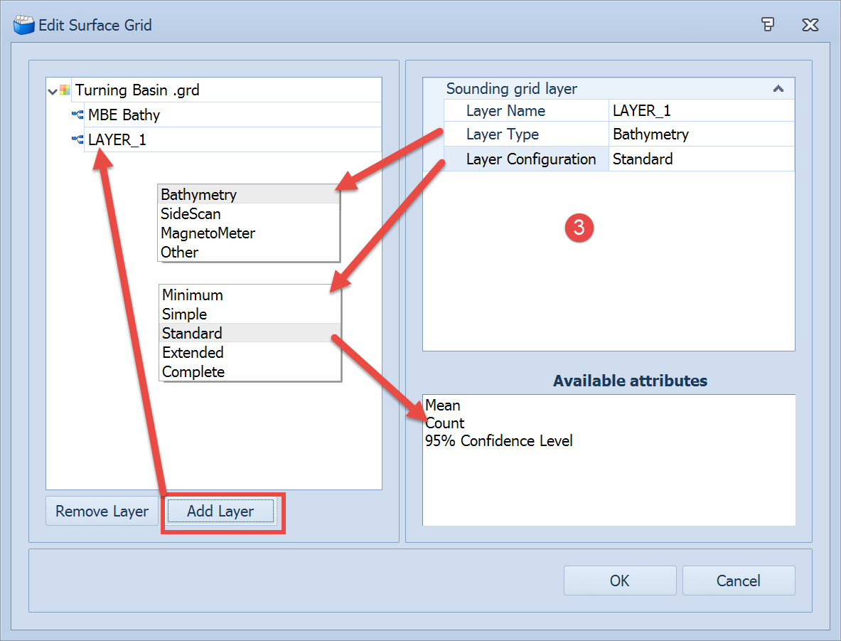
Click on 
Set the Name, Type and Configuration for each new layer added. Each configuration lists in the pane below a different set of attributes that are stored during data acquisition.
Click OK to complete the grid definition.
Return to top of page.
Importing a Design Model to a Sounding Grid
At time of writing (Nov. 2016) there are three different options for importing a design model:
1. Controller - Settings - Session Setup - Storage - Sounding Grid (*.pts/*.grd)


Overwrite existing data - the value in any cell already populated will be replaced with the imported value.
Merge with existing data - the imported value for a cell will be added to the existing value and a new mean value is computed.

Return to: top of page.
2. Processing Manager - Grid Tools - Import (*.QGF/PRO)
Make sure the sounding grid you want to import to is already created with the layers you want.
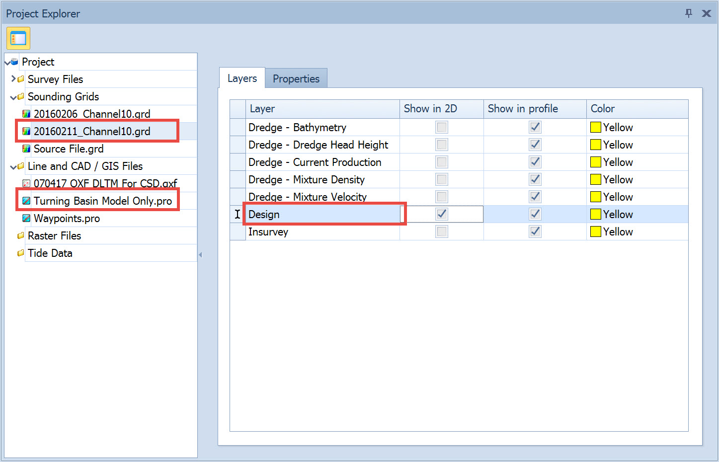
Make sure the design model *.QGF/PRO file is loaded into the project or the import will not work. It can be loaded by importing.
This file has some particular needs: please refer to Line Database Manager.
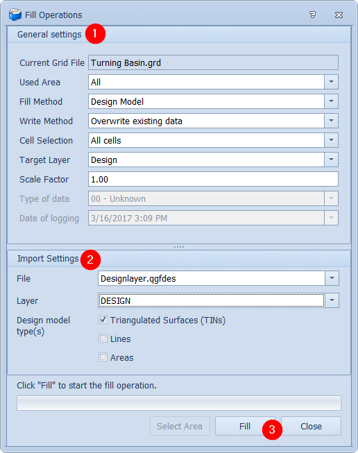
This opens the Fill Operations dialog.
Make entries and selections under General Settings.
Fill method is Design Model.
|
General Settings |
|
|---|---|
|
Current Grid File |
The grid file that was selected in the Project Explorer is shown here.
|
|
Used Area |
All - All available space is used to import data into the grid, including data which might not currently be visible in the Project View.
|
|
Fill Method |
How should the grid be filled: with a Points File / Single Value / Interpolation / Extrapolation / Design Model / Geoid Model / Other Grid.
|
|
Write Method |
Overwrite existing data: the value in any cell already populated is replaced with the imported value. Merge with existing data: the imported value for a cell is added to the existing value and a new mean value is computed. |
|
Cell Selection |
Choose which cells should be filled: All cells: Any cell for which there is a value in the imported data is written into the SG layer. Whether the imported value replaces or merges with a previously existing value depends on the write method selected.
|
|
Scale Factor |
This is a multiplication factor which is applied to the data during import. For example if the original sounding points are in meters and you want to import soundings expressed in feet, enter the scale factor to convert feet to meters.
|
|
Target Layer |
Select the layer of the existing grid into which the imported data are to be written. |
|
Type of data |
Reports the system used to collect the data being imported.
|
|
Date of logging |
The date of collection of the data to be imported.
|
The list contains only XML/DXF/PRO files that have been imported into the Processing Manager.
Choose which layer in the design model file that is to be imported.
Choose which object type(s) (TINs, Lines and/or Areas) should be used as the design model.
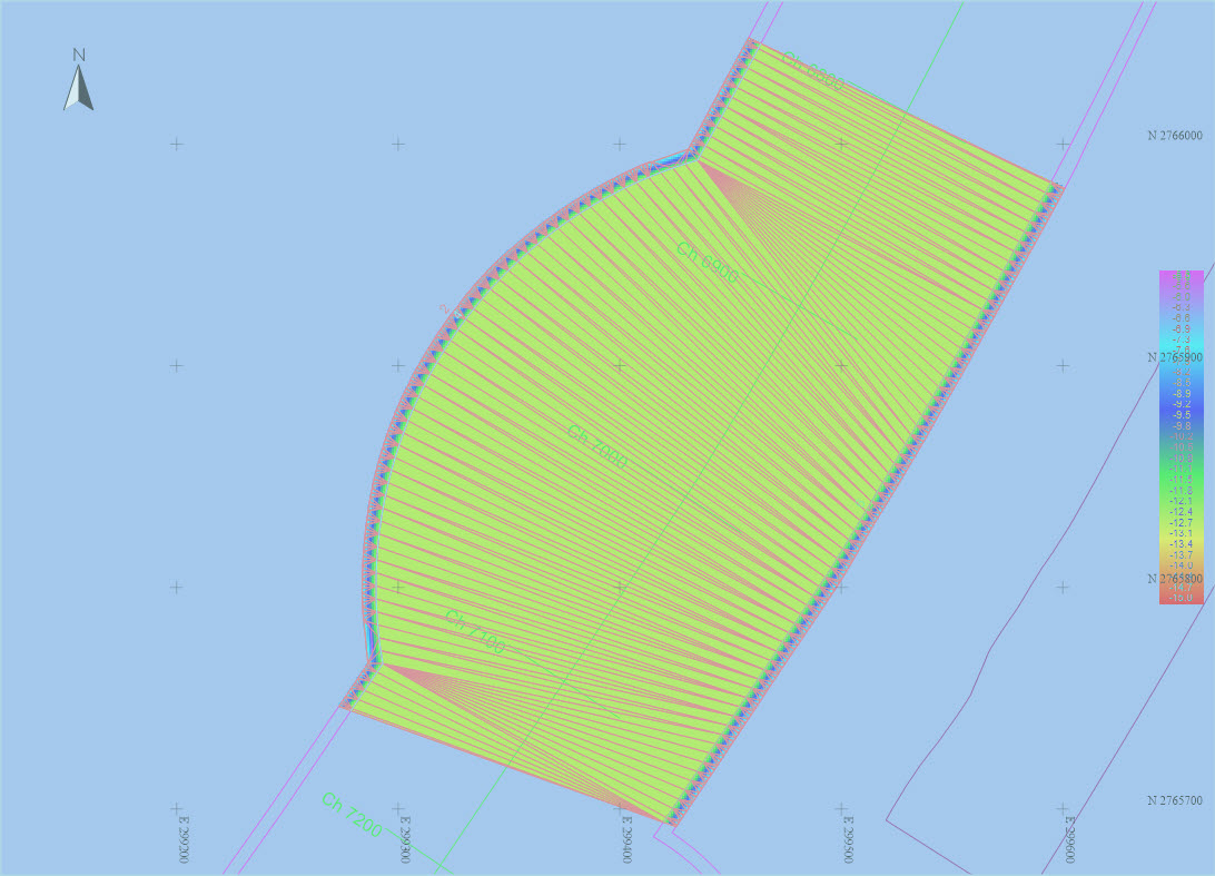
A progress bar indicates the status of fill operations. When Finished click close. The filled grid layer is now shown in the plan view.
3. Stand alone SoundingGridUtility.exe
This program is no longer available since 2018. All its functionality is available in the other two grid creation programs.
Start the SoundingGridUtility.exe program located in the \\Program Files (x86)\QPS\QINSy 8.1 folder.
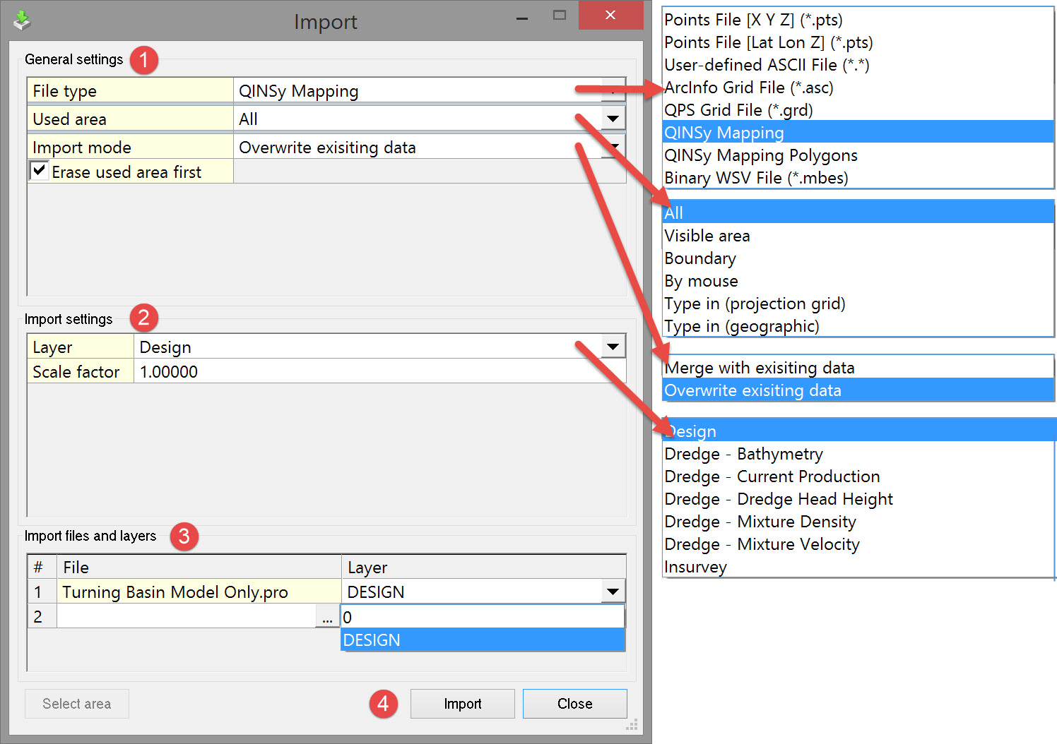
Then in the File menu select Import. This opens the Import dialog.
Enter General Settings.
|
General Settings |
|
|
|---|---|---|
|
File Type |
Select which type of file is to be imported. |
Which types are available depends on the unit set during the creation of the grid file. |
|
|
Points File [X Y Z] (*.pts) |
Space or comma delimited ASCII file (XYZ or ENZ). |
|
|
Points File [Lat Lon Z] (*.pts) |
Space or comma delimited ASCII file. |
|
|
User-defined ASCII File (*.*) |
If the file to import or export is of a format not, by default, supported by the sounding grid utility and the file is in ASCII format, you have the option to define a new format for this type of data. |
|
|
ArcInfo Grid File (*.asc) |
An ASCII data exchange format text file for gridded data. This is a standard format for ESRI systems. |
|
|
QPS Grid File (*.grd) |
Option to import a layer from another sounding grid file, only if cell size and grid origin are the same as the sounding grid to which the data is imported. |
|
|
QINSy Mapping |
A file format output by the Line Database Manager (LDM) which currently (Feb. 2016) uses the Terramodel ToolPak. This is being phased out, probably when the Line Planning functionality in the Processing Manager has the same user experience and functionality as the old LDM. |
|
|
QINSy Mapping Polygons |
A *.PRO file consisting of polygons only. |
|
|
Binary WSV File (*.mbes) |
Specific format used by WSV (The Waterways and Shipping Administration in Germany). The format description can be found in the Controller's Session Setup. |
|
Used Area |
All |
All the data in the particular file type is imported irrespective of the extents of the plan view. |
|
|
Visible Grid |
Only the data that fits into the current extents of the plan view is imported from the particular file type being used. |
|
|
Boundary |
Only the data that fits into the extents of a defined polygon is imported from the particular file type being used. The polygon representing the boundary is selected from a line database file (*.QGF). |
|
|
By Mouse |
Specify an area using the mouse to draw a polygon in the plan view. Use the left button to locate each vertex and the right mouse button to finish defining the polygon.
|
|
|
Type In (Projection Grid) |
Enter minimum and maximum values for Easting and Northing. |
|
|
Type in (Geographical) |
Enter minimum and maximum values for Latitude and Longitude. |
|
Import Mode |
Overwrite existing data |
The value in any cell already populated is replaced with the imported value. |
|
|
Merge with existing data |
The imported value for a cell is added to the existing value and a new mean value is computed. |
There is an option to re-scale the imported data during the import process.
Continue to: Survey Lines
Return to: top of page.
Return to: Quickstart - CSD.