
Highlights on this page

Introduction
21 April 2016, We're pleased to present QINSy version 8.16.0
What is new in this version?
QINSy software is continuously being improved and new features are added. The following is a summary of the changes made. If you have any questions, please do not hesitate to get in contact.
The main changes in this version are:
-
Kongsberg multibeam systems to use a Common reference center
-
Online Quick profile
-
Online new display : 3D Point Cloud Display
Try the Quick Profile option in the Navigation Display. Add the button to the Toolbar by right clicking on the toolbar.
Improvements
Kongsberg multibeam systems to use Common reference center
In previous releases, clients would need to enter the actual Tx/Rx phase center locations or a common acoustic center. These were offset from the geometric center of the arrays. From now on QINSy computes the actual phase centers of the transmitter and receiver relative to the reference position (typically the geometric center of the transducers). For systems that are configured as having a common acoustic center this means that we are able to perform better footprint calculations.
This does mean that the resulting data is different from previous QINSy releases. This change brings QINSy in line with how Kongsberg SIS and Qimera are handling data.
When you select a project which contains Kongsberg systems, this is automatically detected and you will be prompted by a dialog whether you would like to update the offsets in your Template Setup.
For Online surveys, this process starts automatically.
For the Replay of data, however, you will need to add the MultibeamPCONodeUpdater.exe to the lower pane of the Console manually and you will need to update every database separately.
More details can be found in the Knowledge Base document 'How-to Kongsberg Multibeam - Reference Position'.
Starting Qimera from QINSy
Three new options exist to start Qimera from QINSy (if you have Qimera installed and hold a valid license):
-
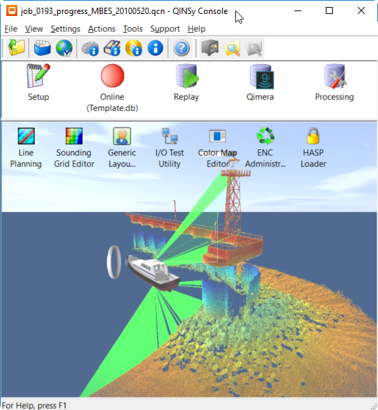
From the Console
-
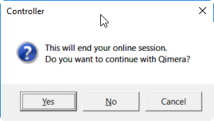
During recording you can close the Controller and the above question will pop up
-
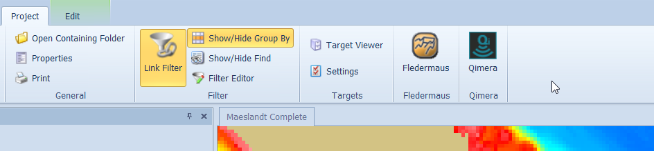
From the Processing Manager - Project Ribbon Tab
Processing Manager
Project Explorer
A new project explorer has been implemented in the Processing Manager, making possible some extra sorting options:
-
Grouping
-
Active layer/file
Selection for editing can only be done from the Project Tree.
Grouping functions - Make it possible to organize your projects. For survey files we added group by Vessel and Date, but it is also possible to make custom groups. You can even make groups inside groups.
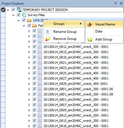
Right-click on a folder to find the Groups option, which can then be used to select a sorting option
Grid Tools Ribbon - Generalize
Create a product surface from a sounding grid by applying cartographic generalization in order to reduce unnecessary detail.
Generalization is a de-focusing technique that works on a grid. It will make the grid suitable for contouring at a particular scale, e.g. 1:2500 where it preserves the locations and depths of shoals. Contours that are generated on this new grid are more pleasing to the eyes as unnecessary details are no longer seen (but shoals are still preserved).
The Generalize function serves to prepare a sounding grid for use as the basis for creating for instance an electronic navigational chart.
The function generalizes the entire grid file that is currently selected.

Generalize button in the Edit Grid Tools Ribbon
Calculate optimum Line Spacing
When creating Wing Lines or Cross Lines in the Line Tools it is now possible to have the optimum line spacing calculated.
This will be based on depth, multibeam angles and required overlap.
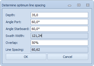
By pressing OK, the spacing value will be transferred to the creation dialog, where it can be adjusted if necessary
Edit Objects - Edit Lines/Polylines
Option to switch between showing geographic coordinates in Survey datum or source datum
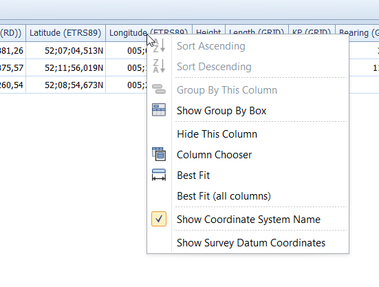
Right-click on the column header of the coordinates to be able to select the option from the drop down menu
Create Vertical Offset Model
Under tab Line Tools create a Vertical Offset Model for use in the Database Setup.
The model is usually created from imported points, using either the DTM Link option to create a triangulated model or by creating a grid model.
This model can be exported for use in Database Setup.
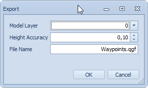
A model will receive the extension .qgfvom
See the documentation in our Knowledge Base: ''
Generic Layout Editor
Additional operators
The following operators have been added:
ASIN: Arcsine
ACOS: Arccosinus
ATAN: Arctangent
All the available operators can be found in the Help file of the Generic Layout Editor:
QINSy Online
Dynamic work area
In the Controller's Settings - Session Setup an option for Monitoring has been added.
A Monitor Area is specifically created for monitoring the whereabouts of an ROV lowered through a moon pool.
To be able to use this option, a second object, for example the ROV needs to be present in the Database Setup.
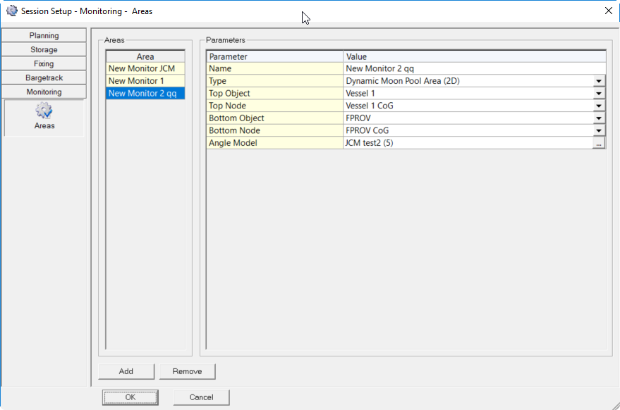
Predefined areas can be selected to be used for monitoring in the Navigation Display.
A Howto document for this functionality has been added to the Knowledge Base: 'How-to Monitor - Dynamic Moon Pool Area'.
Gaussian dump
In Database Setup, under Dredging Systems a new type has been added that can be used to update a grid based on a Gaussian distribution model. The parameters for the model such as height,size, location and rotation are provided by an external system.
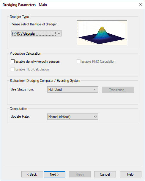
Update the used grid with this model when dumping material
Online DTM output new format
When carrying out surveys which create a considerable flow of data which needs to be used as input for third party software, the Controller - Options - DTM Socket Output option can be used.
A new binary format is available for this purpose.
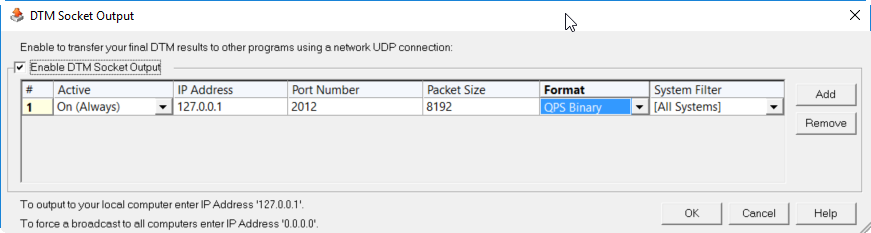
Select the format to be transferred
3D Point Cloud Display
This display shows Multibeam point data in 3D.
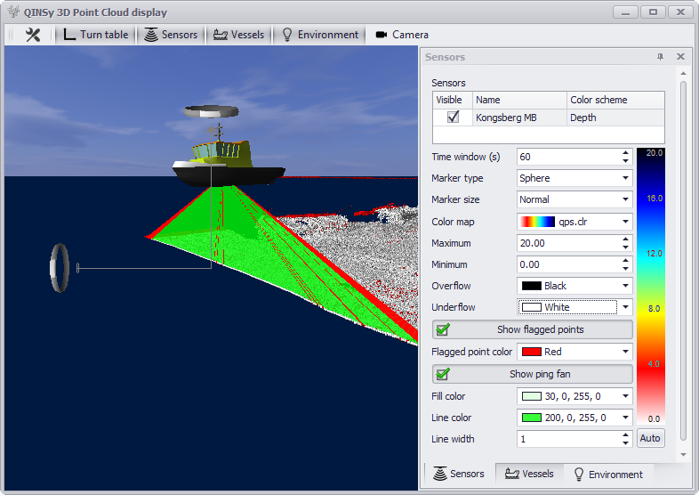
The colors and points can be adjusted to your liking
Navigation Display - Quick Profile
An option added by popular demand from customers: Quick profile in the Navigation Display.

Quick Profile option in the Layers menu
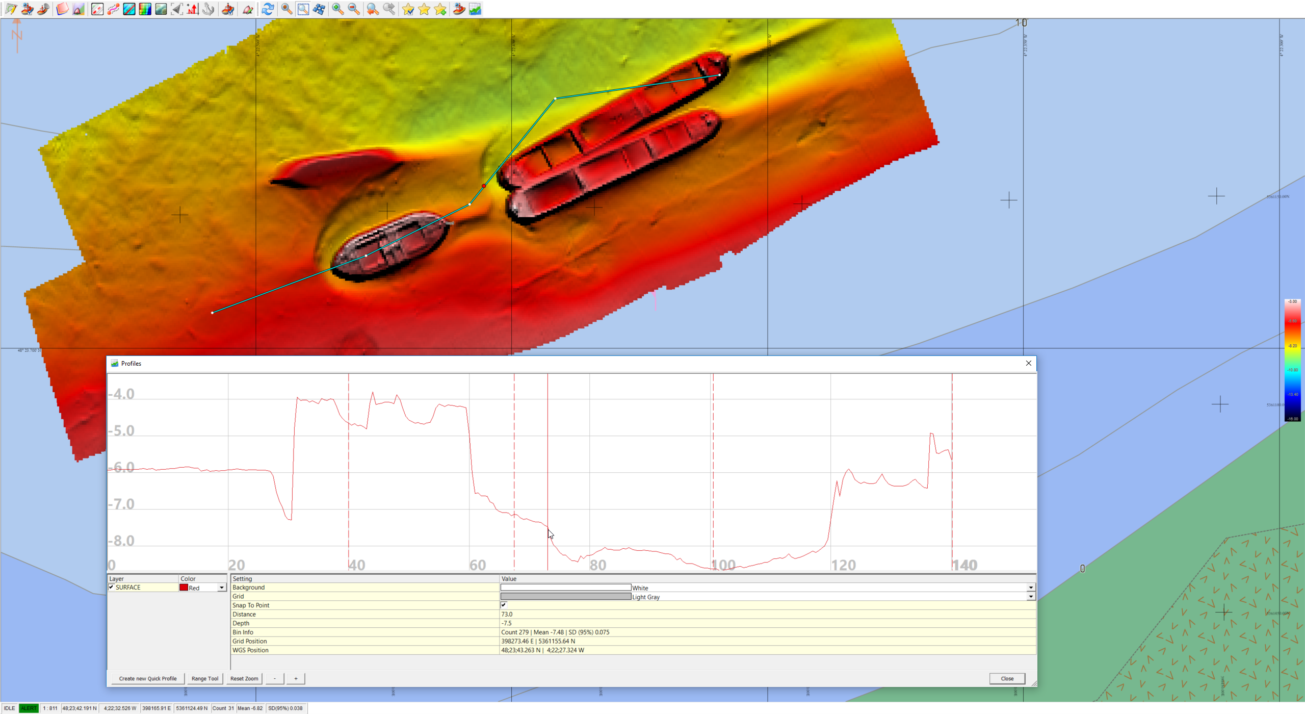
Use your mouse to draw a profile across the grid data available in your display
FQI-16 - Getting issue details... STATUS
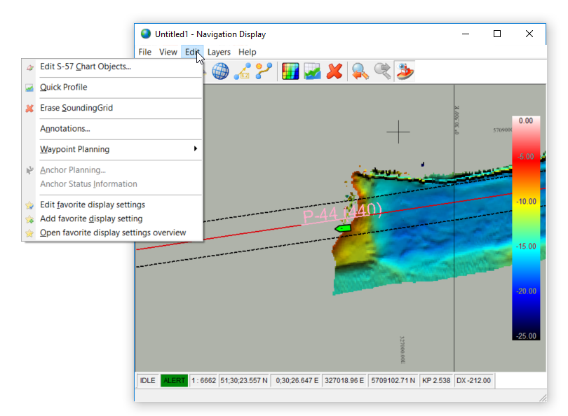
Navigation Display - New default toolbar and new menu
To simplify the use of the Navigation Display an Edit menu has been added that contains all edit options.
Also the default menu that is shown is only the Main menu with just a limited number of buttons.
It is still possible to add other menus and to add separate buttons.
Geodetics
Geoid models/Vertical Coordinate Reference system
Vertical Coordinate Reference system are upgraded from *.PRO to *.QGF format.
Models can be created from Processing Manager
Drivers
Sonardyne LNAV
New driver to decode the Position, gyro, motion, depth, altitude Sonardyne LNAV (Position) - 12
OPC server plugin driver
The name of the OPC server is fixed. OPC Server Plugin - 15
Trimble UTC time message UDP driver
Network version of a driver that can use the Trimble UTC timetag. FQI-71 - Getting issue details... STATUS
UDP version of iXBlue STN BIN driver
In addition to the serial and TCP version of the driver there is now also the UDP version
Geometrics G882
Driver for Geometrics G882, this instrument provides an easy format and was normally interfaced as a generic system. However, since it is widely used it has been decided to add a dedicated driver. Magnetometer (Geometrics G880) - 35
Velodyne preset mounting configuration
For the Velodyne VLP-16 there is now the option to select the mounting configuration from a drop-down list. This simplifies the configuration.
Documentation
-
In our Knowledge Base a new a Howto document is available named 'Howto Cable Catenary'. This describes how to operate the cable lay option.
-
'Howto ADCP' can be used to set up current measurements around your vessel.
-
As mentioned in the paragraph about Kongsberg at the top of this page from now on QINSy computes the actual phase centers of the transmitter and receiver relative to the reference position.
Read this document for a more detailed explanation: 'Howto Use a Reference Position with Kongsberg systems'. -
A Howto document for Monitoring functionality has been added named: 'How-to Monitor - Dynamic Moon Pool Area'.
-
Also new is: '', about creating Vertical Offset Models in the Processing Manager for use in Database Setup.
-
'How-to Import Cathx PCP files' can be used for displaying Cathx Ocean's 3D point cloud in QINSy.
-
Working with the wireless version of the Valeport Mini SVP Logger? Read this document to start the logging process: 'How-to Connect Logger Valeport Mini SVP Bluetooth version'.
Resolved Issues
Below a list of important issues that have been resolved in this release. This list is not extensive.
Processing Manager
-
A persistent bug with the import of DXF and other data has been resolved. The problem was that the data would not be visible after the import
-
3D pane no longer available, there were several issues with this view and made this already non functional for a few releases
-
Column header for latitude longitude incorrect, the header could show the incorrect datum. This has been resolved
-
Vertical reference model from points file. Can now be created
-
WSA GEOBAS: a separate import function has been added, it used to be part of another WSA import and this caused confusion
-
Contour labels are always black
QINSy online
-
Setup of Edgetech sub bottom profiling system, a problem whereby the setup wizard would give an error. This has been resolved
-
Problem where Camera driver would crash after a while. This has been resolved
-
Comparison between SV sensor and profile not computed in Alert Display. This has been resolved
-
ADCP data not corrected correctly. This has been resolved
-
ADCP Display not working on remote
-
Displays on remotes, newer displays were not showing on remotes
-
Sound Velocity Update Rate of Kongsberg Controller can be set to a user defined value
-
Comparison between mini SVS and profile not computed
-
The correction for the movement of the vessel of ADCP data not correct
-
Shift in Z+F profiler 9012 data
-
DspSubBottom - fixes for variable sample size
-
Problem when adding Edgetech SBP system to setup
-
Intrusion detection problems
-
Displays should be in alphabetical order
Known Issues
For this release the following issues have been reported:
|
Component |
Issue description |
Solution |
|---|---|---|
|
Processing Manager/Navigation Display |
Memory problem with CAD files which contain many complex Blocks. |
Simplify the Blocks in the used source file.
|
|
3D Point Cloud display |
Display crashes on some computers with an Intel Graphics card |
A solution is being worked on. If multiple graphic cards are available on the computer, always select the NVidia or AMD card to run the 3D Point Cloud Display. |