
This document describes how to create simple design models in the Survey Manager. Design models can be used e.g. for dredging operations or volume calculations.
The document will explain how to create design models using points, lines or polylines.
Each type (point, lines, polylines) will show you a different way of creating a design model..
On this page:
Create New design model
Open the Survey Manager.
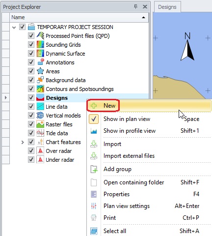
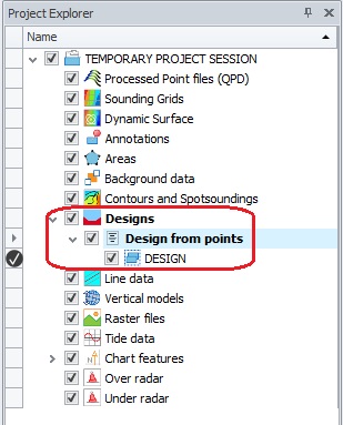
Create a new design file by right clicking in the Project Explorer on 'Designs', selecting 'New' and entering a name for the design.
Info
It is also possible to open the Survey Manager using the 'New Line Data' option. Then you will automatically get the option to create a new Linedatafile: select Design (.qgfdes).
Points
It is possible to create a design based on points. This can be done either by entering the coordinates of points (1), by clicking in the plan view to create points (2) or by importing points (3).
(1)
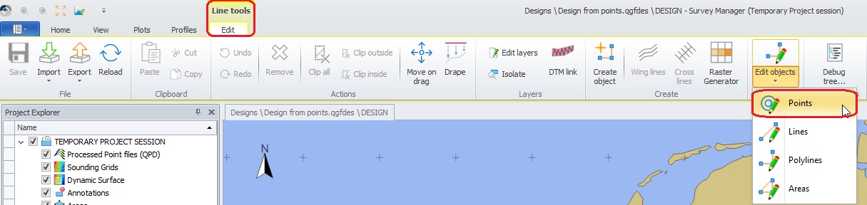
Select the layer in which the design should be created.
Then select from the 'Line Tools menu' the 'Edit Objects' and then 'Points'.
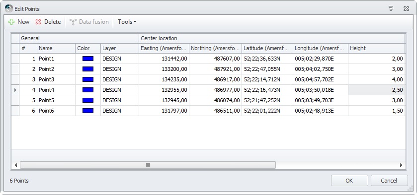
Click on 'New' to create points for the design and enter Easting, Northing and Height for each point (Latitude and Longitude will be calculated automatically).
(2)
Or select 
Afterwards select 
(3)
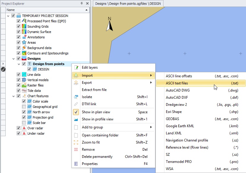
The 3rd option is to import a point file. Right click on the design and select 'Import'.
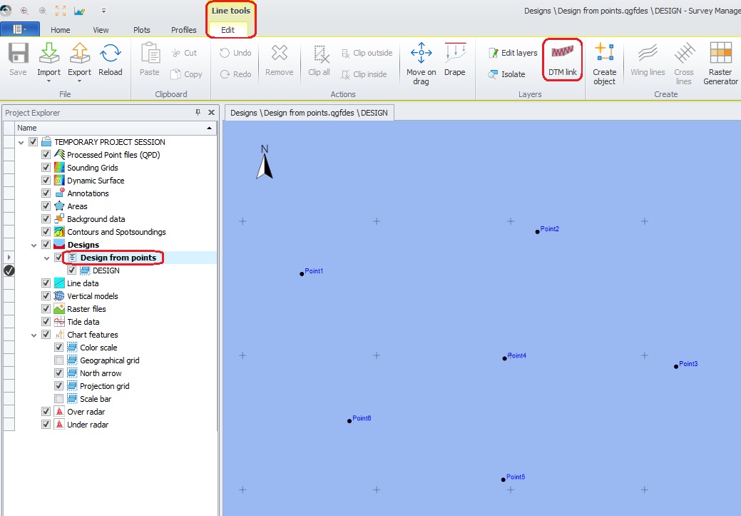
Now the points need to be linked.
Select the design file and select 'DTM Link' from the Line Tools menu.
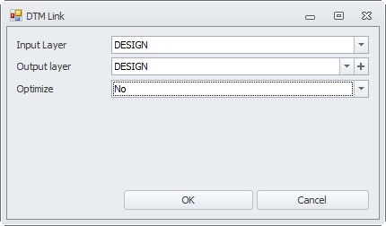
Press 'OK' to create the design.
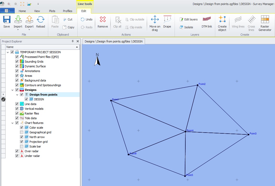
To easily check the created design draw a Quick Profile over it.
To do this, select 'Quick Profile' from the Profiles ribbon, and draw a line in the plan view (left click and right click to end the line)
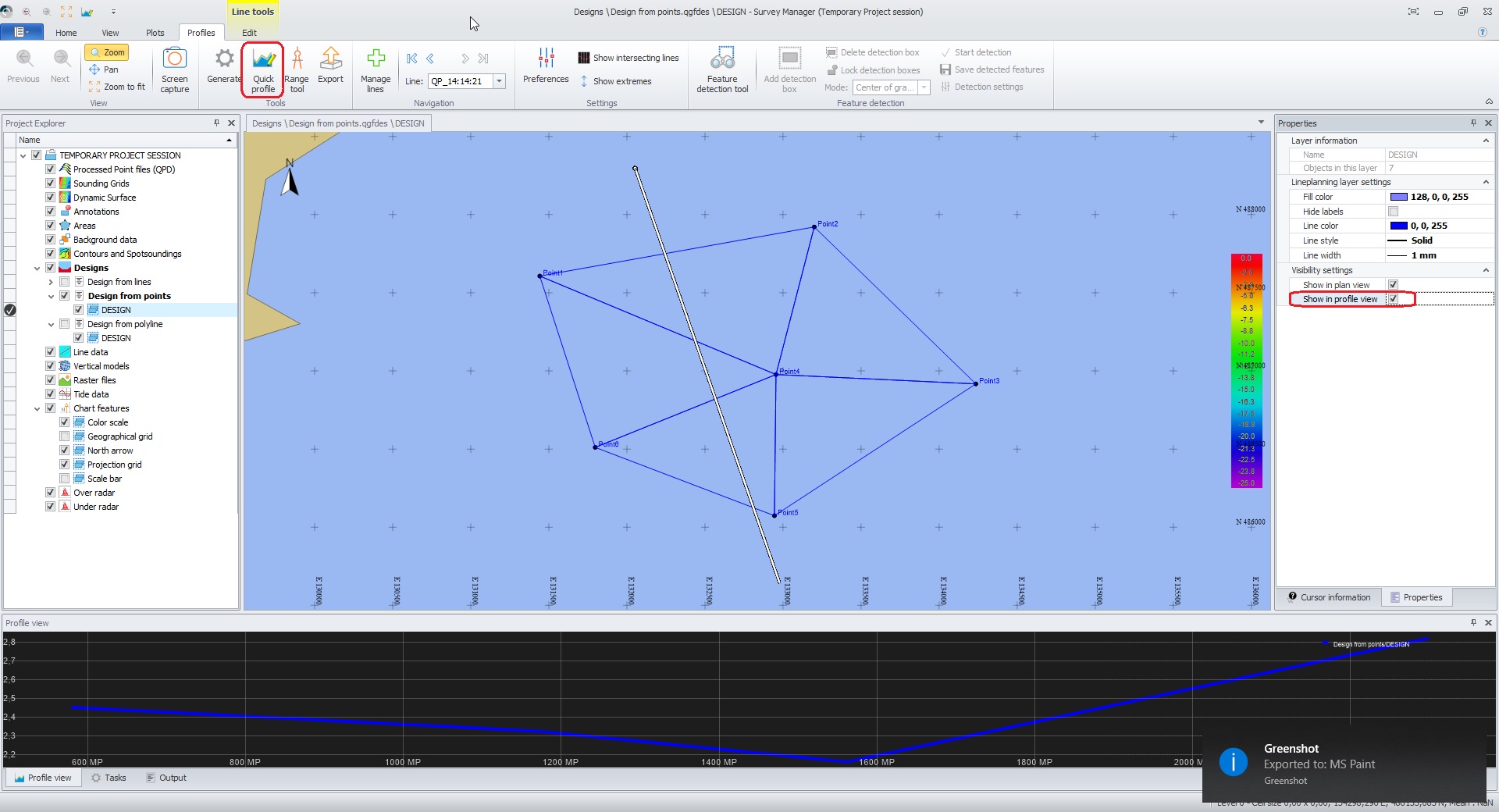
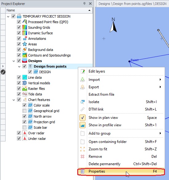
Make sure that under Properties 'Show in profile view' is enabled.
To access the properties, right click on the design and select 'Properties':
Lines
It is possible to create designs based on lines. This can be done either by clicking in the plan view to create lines (1), by entering the coordinates of the lines (2) or by importing lines (3).
Number (2) and (3) are not shown below, but the entering of coordinates or the importing of lines is done in the same way as with points.
It's also possible to create cross lines and wing lines based on an existing line (4).
(1)
Select the design in which the lines should be created. Then select from the 'Line Tools menu' the 'Create Objects'.
Now draw a line in the plan view (left clicks to draw the line, right click to end the line) and enter a name for the line.
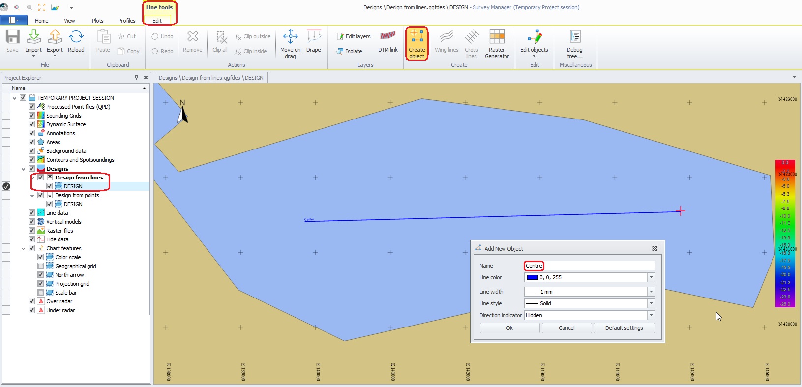
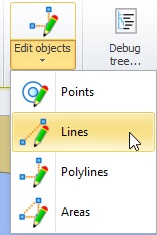
Make sure the line is still selected and select 'Lines' from the 'Edit Objects':
Enter heights for the line:

(4)
Select the Line in the plan view and select 
Create Wing Lines:
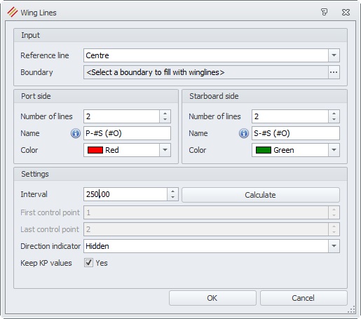
Select 'Lines' from the 'Edit Objects' menu and change heights for the lines:
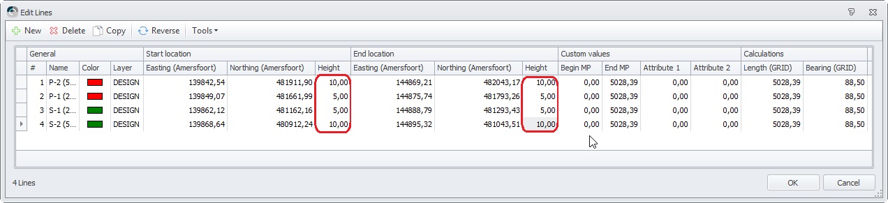
The winglines get by default the same heights as the original line.
Now the lines need to be linked. Select the design file and select 'DTM Link' from the Line Tools menu.
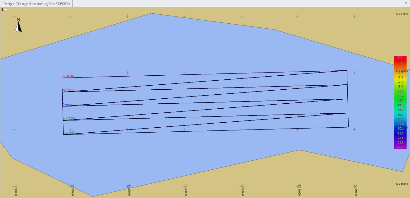
Create a Quick Profile over it, to check the design.

Polylines
It is possible to create designs based on polylines. This can be done either by importing polylines(1), by selecting 'Polylines' from the 'Edit Objects' from the 'Line Tools' menu and entering coordinates (2) or by selecting 'Create Object' and drawing it in the plan view (3).
Number (2) and (3) are not shown below, but the entering of coordinates or the drawing of polylines is done in the same way as with points/lines.
It is also possible to create cross lines and wing lines based on an existing line (4).
(1)
Right click on the design, select 'Import' and 'ASCII Text Files'.
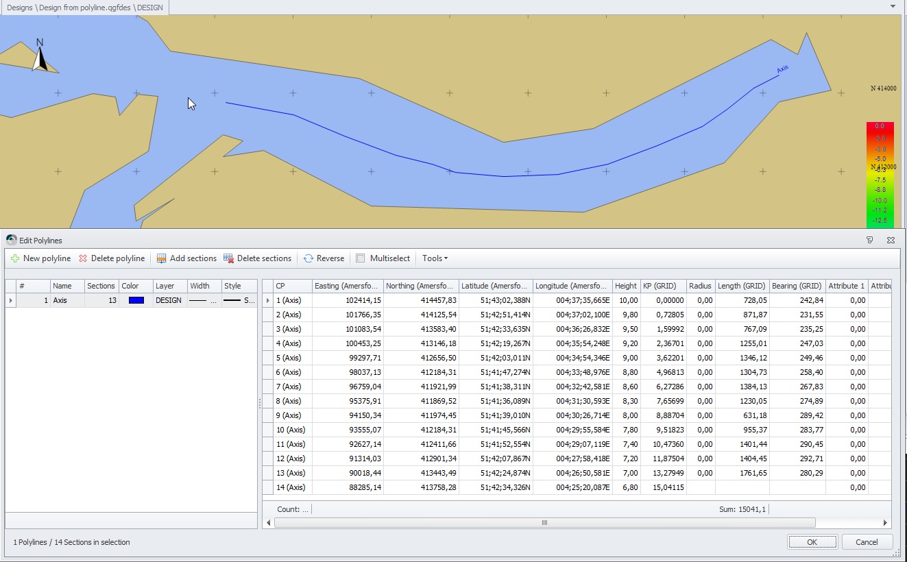
As an example we will import the axis of a river.
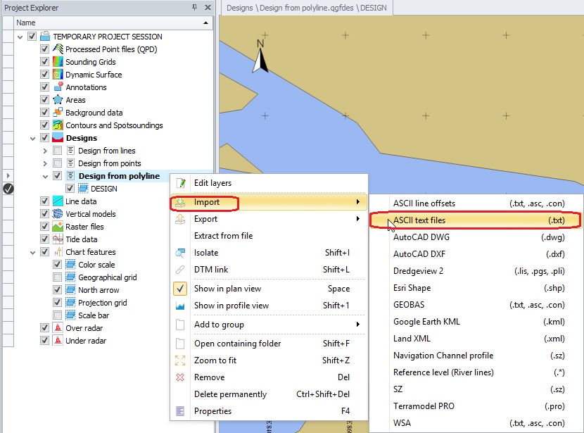
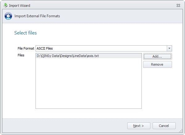
Select the file to import:
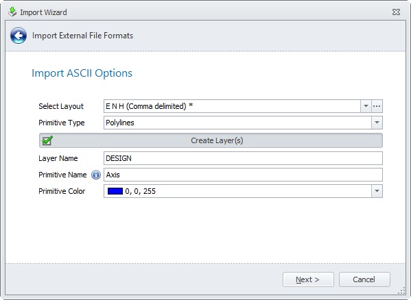
Select the layout of the file (or click on the browse button [ ... ] to create your own layout), select Polylines as primitive type, enter a layer and a name.
Note that the heights for the river axis are imported from the text file.
(4)
Select the polyline and create wing lines in the exact same way as described above for lines.
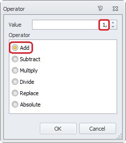
To change the heights of the wing lines, it's possible to use an operator. Select from 'Edit Objects', 'Polylines' and select the polyline of which you want to change the height.
Select all heights and select 'Apply Operator' from the 'Tools' menu:
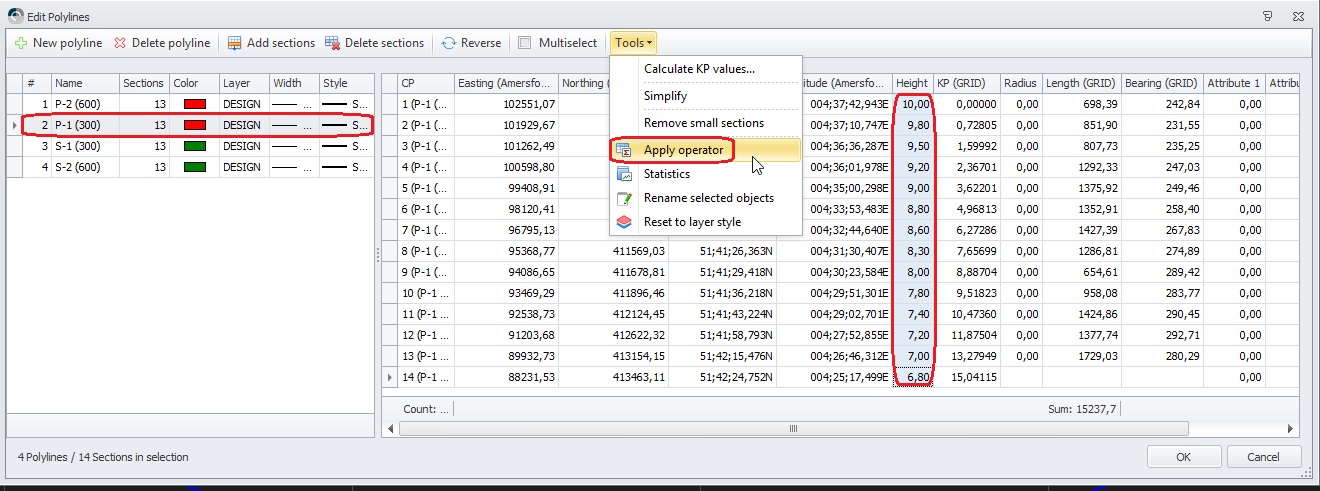
Select the operator you require and Add a value. So e.g. when the wing lines should be 1 meter above the original line:
Now the polylines need to be linked.
Select the design file and select 'DTM Link' from the Line Tools menu.
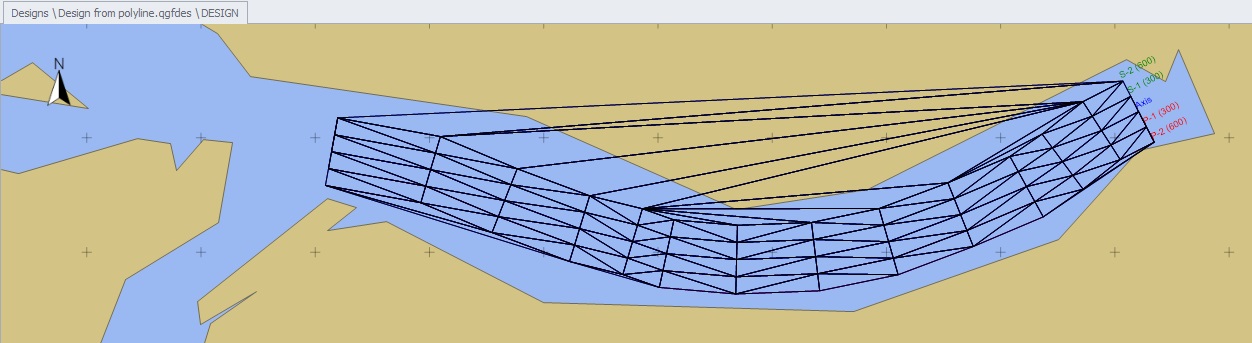
Links are also created now at locations where you don't want them.
This can be changed by using 'Optimize' when creating the DTM Links and entering a Link angle and link distance:
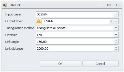
These are maximum values, so in the example below, links that are longer than 2000 survey units will not be created.
Select 'DTM Link' again. When using Optimize, the original links will be overwritten.
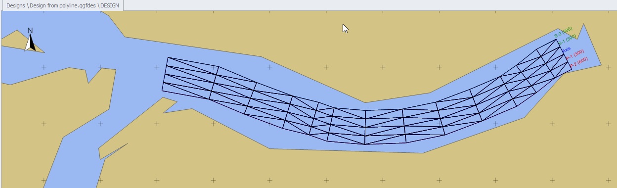
Create a Quick Profile over it, to check the design.

Info
The heights of the design are always relative to the survey datum.
Info
It's also possible to make designs based on a combination of points, lines and/or polylines.