How-to Calibrate a Multibeam Echosounder (Patch Test)
This document will explain how to calibrate a multibeam echosounder (single head and dual head).
A multibeam calibration is performed by sailing a particular pattern, followed by the calculation of the mounting offsets of the multibeam transducer.
First the procedure for a single head echosounder will be explained. At the end the procedure for a dual head echosounder will be explained.
On this page:
Patch Test
The mounting alignment offset can be calculated using Validator or the Qimera Patch Test Mode.
It is highly recommended to use the Qimera Patch Test Mode.
To go directly to processing, see:
Why calibrate
The reason that a calibration must be executed is to find the mounting angle errors (roll, pitch and heading) of the multibeam tranducer(s). These can be found by sailing particular patterns.
These errors should be checked at installation and regularly afterwards to see if they are still valid.
This calibration procedure can be used for all types of multibeam systems.
Timing errors
Time errors should be solved by the TTL device (or PPS device) and sound velocity errors should be solved by recording a profile with a sound velocity probe and applying the profile in Qinsy.
A latency check can be done by sailing a line with two different speeds (e.g. 4 and 8 knots) over a slope. A latency error causes a position error of the footprints.
When there is no latency, then the two slopes should be on top of each other in the Validator.
Sailing pattern
For a multibeam calibration it's advised to sail the following lines:
Roll: two lines over a flat area in opposite directions with same speed (transducer tracks on top of each other)
Pitch: two lines over an area with slopes (or an object) in opposite directions with same speed (transducer tracks on top of each other)
Heading: two lines over an area with slopes (or an object), the lines need to overlap half a swath width, in same direction with same speed
If it's possible sail the calibration lines for pitch and roll with the current and against the current, to avoid a crab angle (when there's a crab angle, there can be a conflict between roll and pitch).
This is referred to as 'best heading'.
Tip
It is also highly recommended to store each run line in a separate file, this is for the Patch Test Tool to work out the calibration.
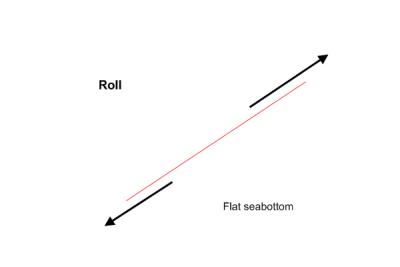
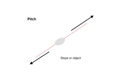
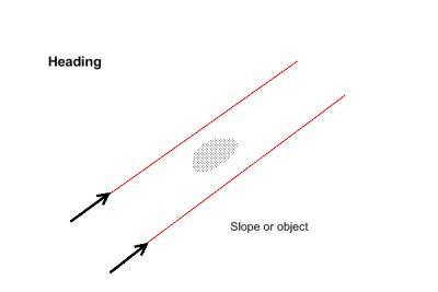
Top View
Calibration of a Dual Head Multibeam Echosounder
The principle of a calibration for a Dual Head Multibeam Echosounder is exactly the same as for a single head. Both heads should be calibrated separately.
The sailing pattern is a bit different, because the transducers are mounted under an angle.
See also the 'Kongsberg EM2040 Dual Head Calibration' document.
Sailing pattern for dual head multibeam echosounder calibration
Roll: for each head two lines must be sailed over a flat area in opposite directions at same speed.
Pitch: for each head two lines must be over an area with slopes (or an object) in opposite directions at same speed (transducer tracks on top of each other).
Heading: for each head two lines must be sailed over an area with slopes (or an object), the lines need to overlap half a swath width, in same direction at same speed.
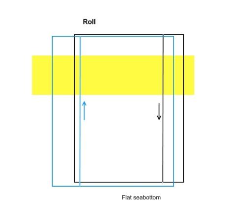
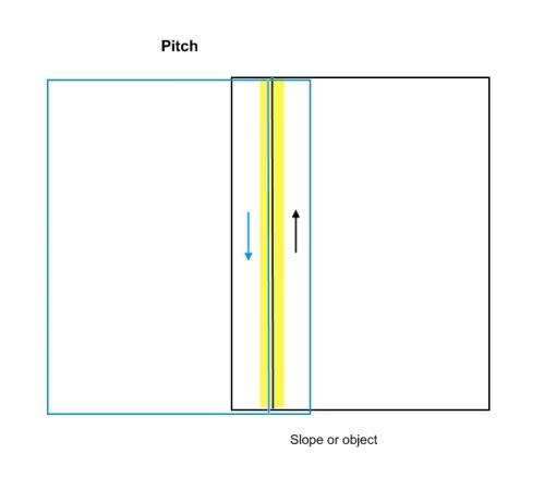
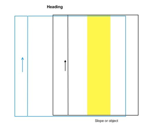
The above examples are drawn for the starboard head.
The blue and the black line indicate the lines that need to be sailed. The rectangle around them represents the footprint data.
The yellow rectangle indicates the area that should be selected in Qinsy or Qimera for the C-O calculations.
Interferometric/Multi-Phase Echosounder
Interferometric/Multi-Phase Echosounders should be treated as dual head systems when performing a patch test calibration.
Please note: Some units, such as the EdgeTech 6205, will use 2 different roll values for each head, and the same Pitch and Heading values for both heads.
Processing (Patch Test)
The mounting alignment offset can be calculated using Validator or the Qimera Patch Test Mode.
It is highly recommended to use the Qimera Patch Test Mode.
For more details see:
