
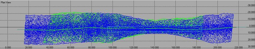
The 3 mounting alignment offsets that can be calibrated are Roll, Pitch and Heading. When there is a roll error in the mounting angles of the transducer, then the result of that will be that a flat, horizontal, seabed is displayed as a tilted seabed.
By surveying the same area two times, one time up and one time down, the result in the Validator will be two seabeds, both tilted but under opposite angles.
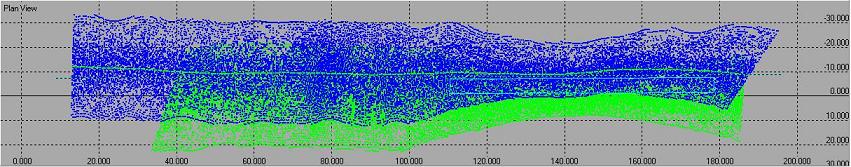
The pitch calibration can be best performed on a slope. The essence of the pitch calibration is shown in the figure below: when there is a pitch error the two profiles will not match.
By surveying the same area two times, one time up and one time down, the result in the Validator will be two seabeds, both with the slope in a different place. For a pitch calibration an accurate positioning system is needed.
The heading calibration can be best performed in an area with a slope or with an object.
When there is a heading error, then the object or the slope will be displayed in two different places in the Validator.
The result looks the same as the pitch error. Because the sailing pattern was different, Qinsy can distinguish between pitch and heading.
Calibration Steps
It is important that the calibration is performed in a certain order. The calibration must start with the roll calibration, then the pitch calibration and after that the heading calibration.
Qinsy uses the rotation matrix in this order for computing footprints.
-
Start the Survey Manager
-
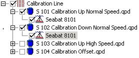
Select all QPD's in the File Explorer used for the calibrations
-
Start Validator

-
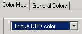
To identify the lines , give them each a unique color by selecting View-Colors-Color Map
-
Clean the data as well as possible before the calibration is carried out. This will improve the calibration results.
The different calibrations are carried out separately from each other.
Roll calibration offline
-
Select the two lines on the same track in opposite directions over a flat area
-
Set the survey line as reference: click right mouse button in the plan view and select: Coordinate System-Surveyline.
If the surveydata is not aligned properly with the surveyline, an alternative line can be drawn. -
Select from the Settings menu, User defined line (or the

Click in the plan view on the left side in the middle of the survey area, then a left click on the right side, if necessary more clicks to extend the line, close/save the line with a right click.
First the area has to be selected for which the roll will be calculated. This should be an area on a flat seabed, perpendicular to the sailed line.
See picture below.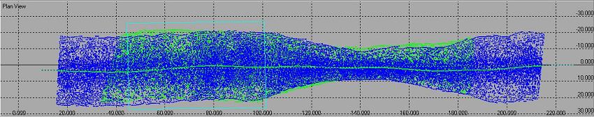
This can be done by drawing a scroll box. -
To draw a scroll box, select from the Scroll menu, Pick Scroll Box (or select

Select from the Scroll menu, Properties (or select
-
Enable the editing/calibration by selecting from the Settings menu, Viewed Data = Validated (or select

-
Activate the calibration by selecting from the Calibrate menu, Transducer Alignment (or select

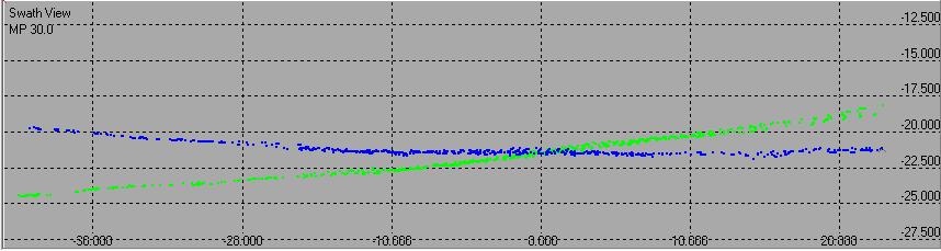
The Calibrate Alignments window appears: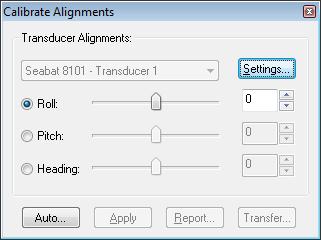
In the Swath View, the data from both lines in the scroll box is visible, each line in its own color:
-
Click on Auto.
-
Select Step – Very Coarse. This way the estimated angle will be roughly calculated.
-
Click on Start. An estimated angle is calculated. If the estimated angle is not in the search area, repeat with the same step size until the estimated angle settles down.
Behind the number of steps, you can find the search area and the used step size. Now the estimated angle will be fine tuned with smaller step sizes. -
Select Step – Coarse. Repeat the procedure.
-
Select Step – Fine. Repeat the procedure.
-
Select Step – Very Fine. Repeat the procedure. -
Move forward/backward through the DTM to verify this for alternative areas. Use

to move around.
-
It is possible to repeat the same steps (7-13) now in different areas.
-
Once several numbers have come up for the estimated angle, take an average of the applicable values.
-
Run through the entire DTM to verify if the swaths match.
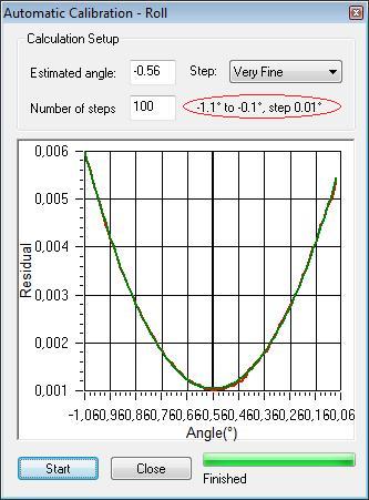
Info
Only use the Estimated angle when the figure looks like a hyperbola.
When it's not a hyperbola (see example below) it's possible the scroll box is selected at the wrong place or the step size to calibrate is too small.
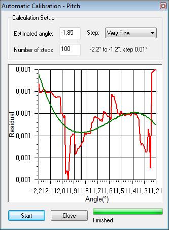
Info
It's not necessary to use the Automatic option, you can also manually enter a value at the Calibrate transducer alignment box (or slide) to find the correct value.
Make sure to verify this value on alternative areas.
Pitch calibration offline
The procedure for pitch is exactly the same, only a different area needs to be defined.
Make sure two lines on the same track in opposite directions are selected (over a slope or object).
These can be the same lines as used for roll, if the lines have a part with a flat seabed and with a slope or object.
Follow the same steps as for calibrating the roll, but select a different area.
You should define your scrollbox over the slope, parallel to the sailed line.
he best is to select the data below the transducer, when you right click with your mouse in the planview, you can enable Show Transducer Data.
See example below:
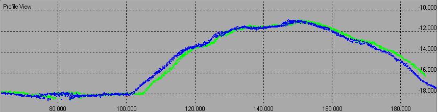
Make sure, that in the Calibrate Alignments window the pitch is selected.
In the Profile View, the data from both lines in the scroll box is visible, each line in its own color:
Heading calibration offline
The procedure for heading is the same, only a different area needs to be defined and different lines need to be selected.
A heading error looks the same as a pitch error if the correct area is selected. But because the sailing pattern was different, Qinsy can distinguish between them.
Make sure two lines with an offset in the same direction are selected (over a slope or object).
Follow the same steps as for calibrating the roll and pitch, but select a different area.
Define your scrollbox over the slope, parallel to the sailed line on the overlap of the two lines, between the transducer tracks.
See example below:
Make sure, that in the Calibrate Alignments window the heading is selected.
In-Depth: How the automatic calibration works
The automatic calibration routine rotates the pings in the scroll box with different angles and obtains the angle at which the difference between both runs is minimized. This difference is named 'residual'.
Interpreting the residual
The residual is calculated as follows: The footprints in the scroll box are divided in a square grid. For each grid cell, a mean height is calculated for every QPD.
Then, for every grid cell, a height difference between the cell belonging to the first QPD and the one belonging to the second QPD is calculated.
The residual is then the average difference between the square of this height difference, over all grid cells.
The size of the grid can be set in the calibration settings. The default is 2x2 survey units.
The final residual, obtained after automatic calibration, is a quality figure for the difference between the first and second run, after calibration. The lower the residual, the better the fit.
Note, however, that if an underwater terrain is selected for calibration that is unsuitable for the task (no slope or object for a pitch calibration, for example) the residual can be low, even though the calibration is poor.
We have seen quality figures of around a millimeter (survey unit: meters) for a good calibration.
Transfer alignment corrections
When the correct parameters have been determined, the found mounting angles should be entered in the Template and in the related recorded databases if the databases will be replayed with new alignment corrections.
This can be done in Database Setup, but it's also possible to use the Transfer option in the Calibrate alignment module.
See screen capture below:
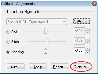
Select the Transfer button, the following screen will appear:
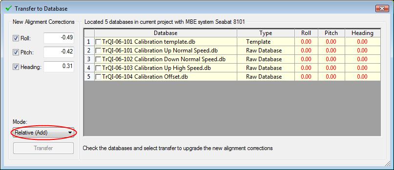
On the left hand side the determined aligment corrections are found and on the right hand side are all the databases in the project (template and recorded) with the alignments that are in the Database Setup at the moment.
Make sure to determine the mode to Transfer.
If Absolute (Replace) is selected then the alignment corrections will be replaced by the new ones.
When Relative (Add) is selected, then the newly determined corrections will be added to the ones that are already there.
Select the databases that the newly determined corrections need to be transferred to and press the Transfer button.
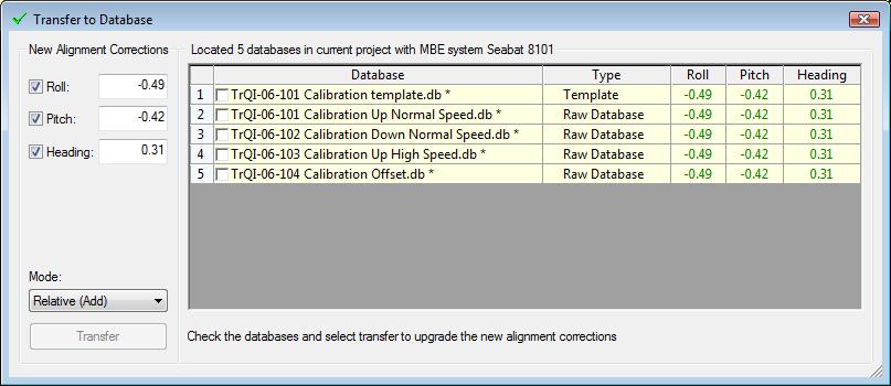
Now the new corrections show up in green which indicates they are changed in the selected databases.