
This article describes the Multibeam calibration procedure for a Kongsberg EM2040 Dual head system as advised by Kongsberg.
On this page:
Step-by-step guide
To carry out a correct calibration the tide and the sound velocity profile MUST be correct.
Roll
Run 3 lines as indicated below in a flat area:
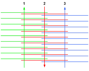
STB
Select lines 1 and 2, make a calibration corridor perpendicular to the lines. In the calibration module select head 2 and adjust the roll value until you have a match.
Move the calibration corridor along the lines to verify your result. Take note of the value you have found.
PORT
Select lines 2 and 3, make a calibration corridor perpendicular to the lines. In the calibration module select head 1 and adjust the roll value until you have a match.
Move the calibration corridor along the lines to verify your result. Take note of the value you have found.
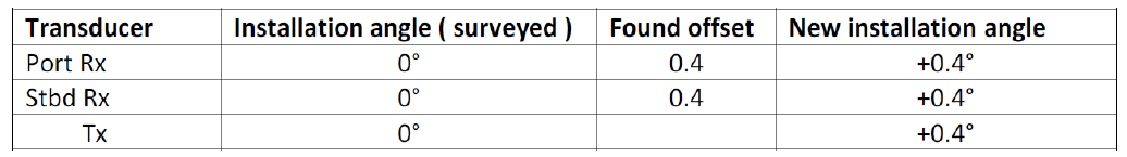
Applying the calibration values found. Example:
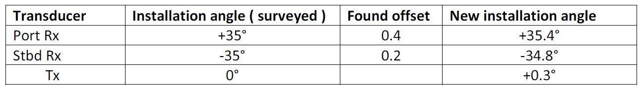
Found roll applied to each RX and the average to the TX
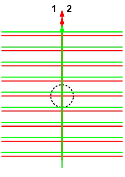
Pitch
Run 2 lines as indicated below over a distinct object or slope:
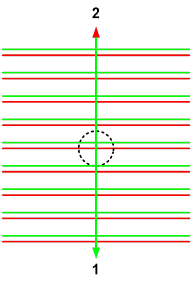
STB
Select lines 1 and 2, make a calibration corridor along the center beam of the lines.
In the calibration module select head 2 and adjust the pitch value until you have a match. Take note of the value you have found.
PORT
Select lines 1 and 2, make a calibration corridor along the center beam of the lines.
In the calibration module select head 1 and adjust the pitch value until you have a match. Take note of the value you have found.
Applying the calibration values found. Example:
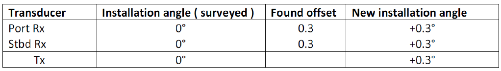
Pitch is to be applied in each RX and TX
Note
If you get different values something is wrong, re-check your setup/calibration.
Heading
Run 3 lines as indicated below with the 2nd line crossing a distinct object:
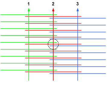
STB
Select lines 1 and 2, make a calibration corridor along the center beam of line 2.
In the calibration module select head 2 and adjust the heading value until you have a match. Take note of the value you have found.
PORT
Select lines 2 and 3, make a calibration corridor along the center beam of line 2.
In the calibration module select head 1 and adjust the heading value until you have a match. Take note of the value you have found.
Applying the calibration values found. Example:
Heading is to be applied in each RX and TX
Note
If you get different values something is wrong, re-check your setup/calibration.
Time
Run 2 lines as indicated below over a distinct object or slope with different speeds:
Select lines 1 and 2, make a calibration corridor along the center beam of the lines.
In the calibration module select head 1 and adjust the time value until you have a match.
Verify the result by selecting only head 2 and by selecting both heads.
Info
In Qinsy there is no option to compensate for any time delay. You must discover the source of delay and fix it.
Rotation of Sonar Heads
Default head mountings are as follows (note where plugs are pointing):
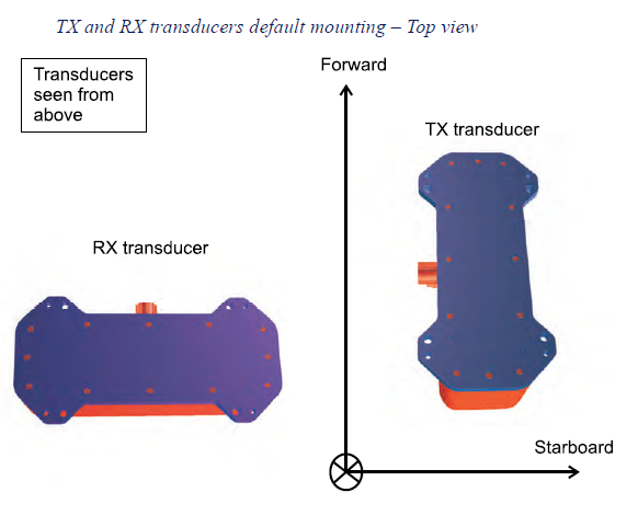
When one of the heads is rotated by 180 degrees, this value has also to be entered inside the database for the respective sonar head.
Roll, Pitch and Heading Calibration values found for the rotated head, must be also inverted.
Example:
RX is 180 deg rotated (plug pointing aft), Pitch value is currently 0.5 deg
Pitch calibration results give 0.1 deg
Value to be applied in database is -0.1 therefore, result will be: 0.4 deg
This applies for the Heading and Roll of the concerned rotated head.
Apply offsets
QPS recommends to apply the offsets as described above if and only if the TX and RX arrays are mounted together on a precisely machined frame that is then coupled with the vessel.
Related articles