How-to Process Pipeline Surveys
This How-to is firstly intended for those who wish to process a pipeline survey in order to obtain pipeline markers, and secondly to smooth the points data obtained during a pipeline survey, so that the data is suitable for charting.
On this page:
Qinsy Processing Steps
1 : Clean swath data
Online/Replay
During the survey or replay the DTM data can be conditioned, this has the effect of pre-processing the data:
- Ensure exclusion and despiking settings are set up to achieve maximum cleaning.
- Ensure that reduction is enabled (echosounder settings).
- Ensure DTM file storage is set to write to \*.qpd (Reduced Qinsy Processing Format) and that the required echosounders are selected.
Processing
Start the Survey Manager from the Qinsy Console.
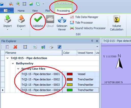
In the File Explorer, select the datafiles and open the Validator from the Processing Ribbon.
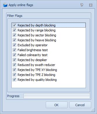
Enable the filters that were used online and press OK.
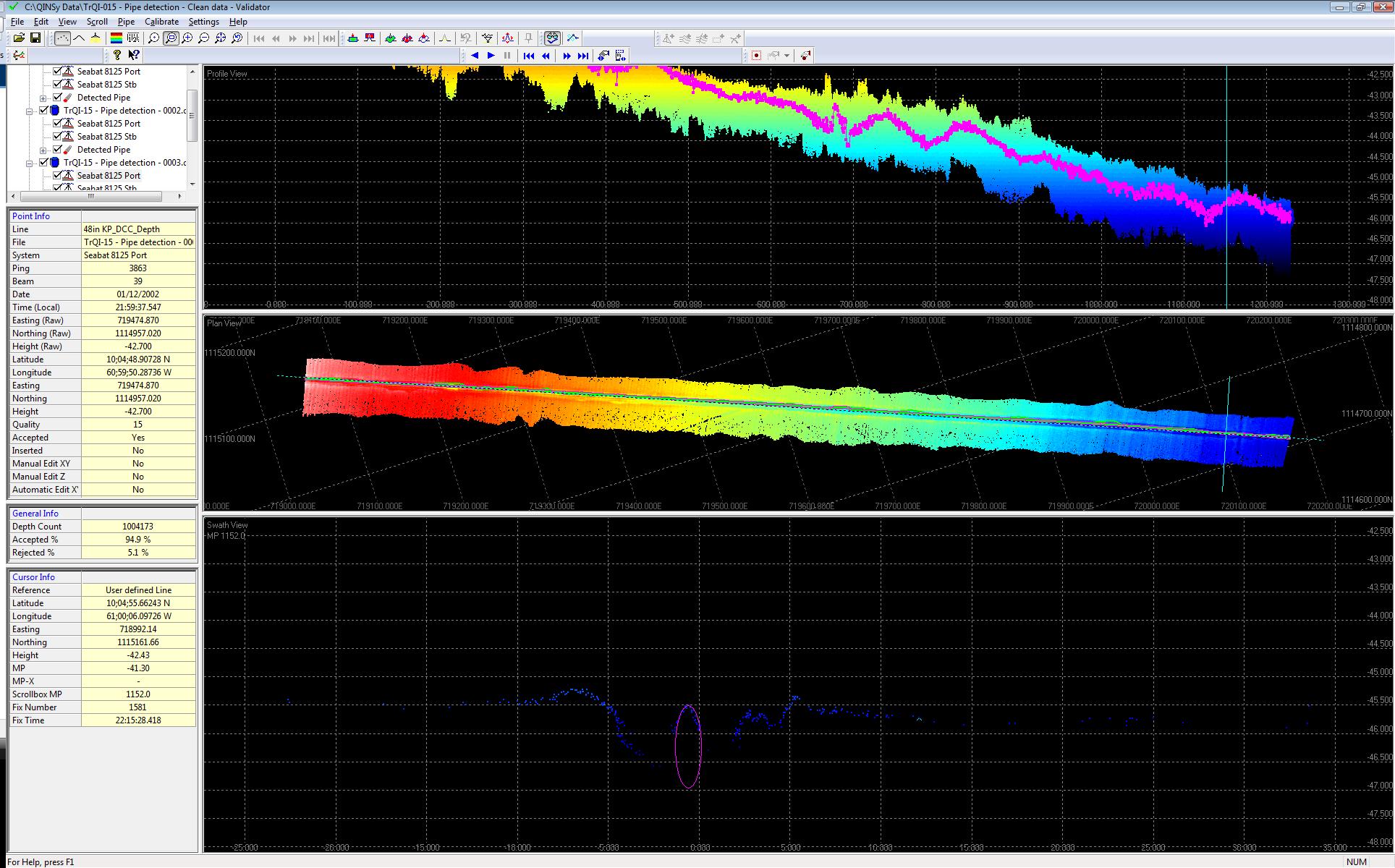
The Validator has different views that show data points from different sides: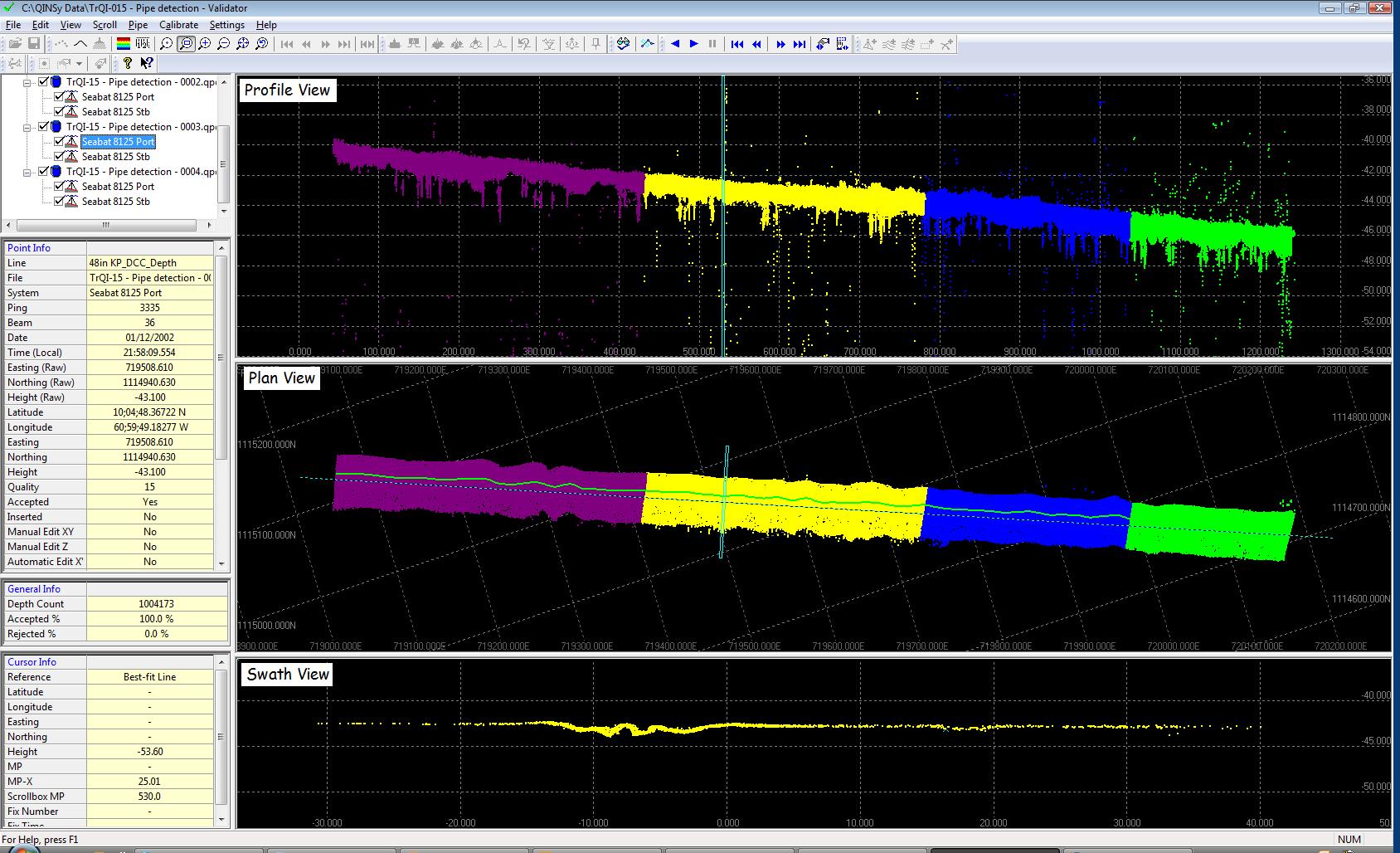
The data in the different views can be shown in different manners by using the View toolbar buttons:
- Show big dots, Join dots with line, Highlight
- Color dialog, Scale dialog
- Zoom / Pan options
- Next line (*.qpd) / Previous line options
It is important to understand that data points shown in the Profile and Swath views are shown with respect to the Scroll Reference.
The scroll reference can either be the survey line (that was active when the data was acquired), alternative survey line (selected from a Line Database), transducer track, or user defined.
When multiple data files are selected, the survey line from one file is used as the Scroll Reference and it is not so that each line is referenced to its own survey line.
The data shown in the swath view is only the data that is inside the scroll box.
The scroll box can be set in width and range and can be scrolled along the scroll reference.
Scroll toolbar buttons, from left to right:
- Playback, Play, Pause
- Beginning of Scroll Reference, Previous, Next, End of Scroll Reference
- Scroll Properties dialog, Pick Scroll Box
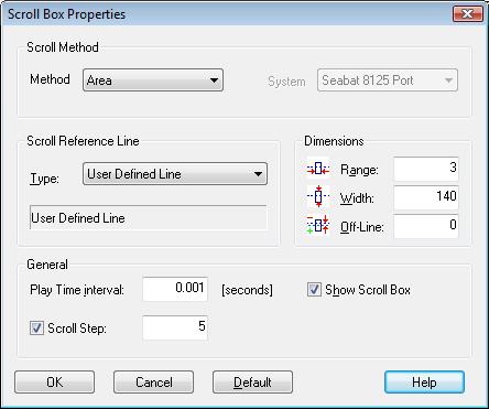
Press the *Scroll Properties* toolbar button, or select the Properties command from the Scroll menu.
| Properties | |
|---|---|
| Scroll method | The selected method determines which data will show up in the swath view. Use area or area/single swath for a dual head multibeam, which can be used for a single head swath as well. |
| Scroll Reference Line | The scroll reference (the origin for the Profile and Swath views) can be selected here. |
| Play Time Interval | Determines how fast the scroll will progress through the data. |
| Dimensions Range | Determines the selection slice thickness. If you arrange the selection slice so that it is wider than several data samples, the mean from the data samples falling within the selection will be taken. To obtain the most reliable “detected pipe”, it is suggested to set the selection range at a thickness equivalent to the data update interval. I.e. when you have data every 0.25m, set the selection range to 0.2m. Alternatively, to calculate the mean over a number (4 or 5) of data samples, set the selection range to 1m. |
When you open the Validator, all data is shown.
Before you can start editing, you must enable the editing mode by clicking the 
In the tree view it is possible to enable and disable sensors: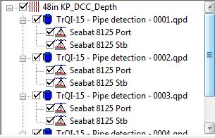
Incorrect data can either be removed manually, or using automatic filters.
Edit toolbar buttons, from left to right:
- Rectangle clip outside (manual), Rectangle clip inside (manual)
- Polygon restore inside (manual), Polygon clip inside (manual), Polygon clip outside (manual)
- Interpolate (interactive)
- Undo • Filter (automatic)
- Shift data
- Lock window in Swath View
The manual functions can be used in any of the 3 views (not 3D view).
In the case below the cross profile view and the manual 'Clip Inside' filter, creating a rectangle around the bad data will remove that data and will update the other views: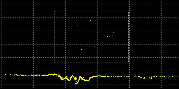
Automatic editing can be done using the filter option.
In the filter function a scheme can be built of several consecutive filters.
This scheme can then be run.
The scheme can be saved for future use.
Info
More information about the Validator and the Edit functions can be found in the F1 inline help.
2 : Detect pipe
Pipe detection serves two purposes.
- Find a pipeline and the adjacent pipe markers.
- Alternatively to derive a shift value that is then used to adjust data so that the pipe appears smooth.
Pipe Tools toolbar buttons, from left to right:
- Detect pipe
- Modify detect windows
- Drag and Drop pipe (used for manual correction of detected pipe position)
Press Detect Pipe toolbar button to open the dialog:
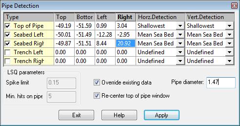
When the 'Detect Pipe' dialog is open the detected pipe position will be stored when you scroll through the data.
This offers the opportunity to change the size of the rectangle whilst scrolling through the data.
The items from top to bottom are:
Type of pipe marker with size of detection rectangle and the horizontal and vertical detection method.
Five different predefined pipe markers are available.
Override Existing Data: enable this option when you want to replace existing detected pipe data.
Re-center top of pipe window: re-centers the detection rectangle around the previous detected top of pipe and moves the adjacent windows in the same direction.
Pipe diameter: is used to show a circle in the cross profile view, representing the pipe.
Detection methods:

| Detection methods | |
|---|---|
| Fixed Value | Used to detect at the middle of the selection rectangle. |
| Shallowest | Used to detect using the shallowest data point, within the selection rectangle. |
| Deepest | Used to detect using the deepest data point, within the selection rectangle. |
| Mean Sea Bed | Used to detect using the mean value of all samples within the rectangle. |
| Least Squares | Used to detect using the least squares method on all samples within the rectangle. |
Use the scroll toolbar buttons to go through the data and to detect the pipe.
Scroll toolbar buttons, from left to right:

- Play back (shift+space)
- Play (space)
- Pause (space or shift+space)
- Go to beginning
- Previous (ctrl+left)
- Next (ctrl+right)
- Go to end
- Scroll Properties
- Pick scroll Box
To detect the pipe, ensure that scroll window (blue slice) is at one end of the data set, click Play / Playback to scroll through in one go, from start to finish (left to right in this example).
Alternatively, use the Next/Previous toolbar buttons to scroll through at your own pace.
When finished, click 'Exit' to close the 'Detect Pipe' dialog and allow the Validator to plot the detected pipe in the View (purple track).
3 : Smooth detected pipe
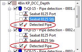
Disable all sensors but the detected pipe.
Select Filter from the edit menu and select 'Active footprints'. Select 'Remove All', and arrange two 'mean' filters: one for Z and one for XY.
By using a mean filter, a smooth detected pipe route will result. The amount of 'smoothness' depends upon the length of the mean filter.
Save the filter scheme, for later use.
An alternative to the mean filter is the 'Butterworth', which is designed to identify the low frequency, and remove the high frequency (noise) values. For this filter, you only have to choose the degree of smoothing from the scale very low to very high.
As with the mean, you can choose to filter only horizontally (X/Y), or in Z direction as well. The Butterworth offers a third possibility (MP-X), namely to smooth in the horizontal plane, but then only acrossline, not inline.
The distance along line of each subsequently shifted swath remains constant.
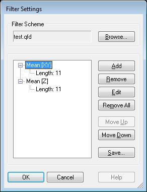
Press OK to start the automatic filter process.
To check the effectiveness of the filtering, you can, for each view, enable 'raw data’ from the right-click pop-up menu.
Here for example, 'raw data' has been enabled in the profile view, and one can clearly see the smoothing effect of the mean filter.

4 : Export detected pipe (As found pipeline)
Close the Validator. Select your QPD file(s) and choose export 'User Defined ASCII'.
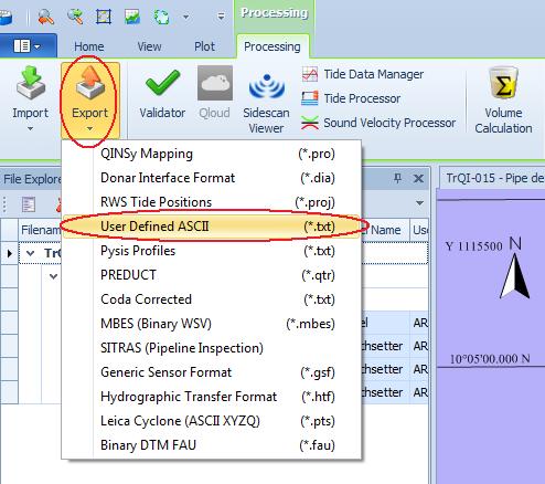
This will start the ASCII export wizard. Select the category to export: detected pipe-DTM points.
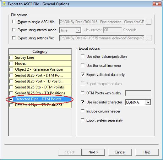
And on the next page of the wizard the items to export.
5 : Shift raw pipetracker data and clean swath data using smoothed detected pipe
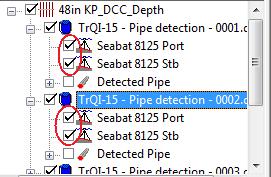
Ensure the swath systems are visible.
Edit toolbar buttons, from left to right:

- Rectangle clip outside (manual), Rectangle clip inside (manual)
- Polygon restore inside (manual), Polygon clip inside (manual), Polygon clip outside (manual)
- Interpolate (interactive)
- Undo
- Filter (automatic)
- Shift data
- Lock window in Swath View
1) Click the 'Shift data' button to open the dialog.
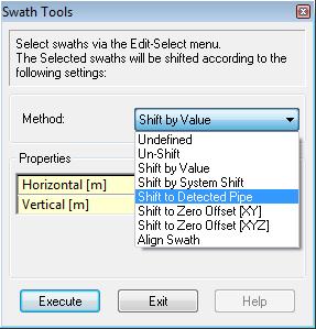
2) Select 'Shift to Detected Pipe'
3) Select the 'Select System' button, click on the raw multibeam data in your plan view or profile view (make sure all the data is selected, colored blue).

4) Press 'Execute' to begin the shift action.
The Validator will now shift the raw multibeam data the same amount that the detected pipe was smoothed.
6 : Export to *.pro for mapping
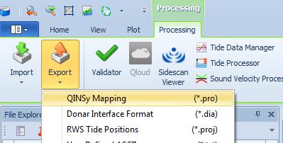
Close the Validator. Select your QPD file(s) and choose export 'QINSy Mapping (*.pro)'.
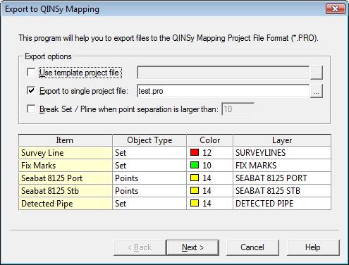
Choose whether or not, each available item is to be included in the export, choose the color, and choose the destination layer name.
One can take the settings from a template \*.pro if preferred.
This can be very useful as every setting and other data from the template will be available in the resulting project file.
Example of datashift:
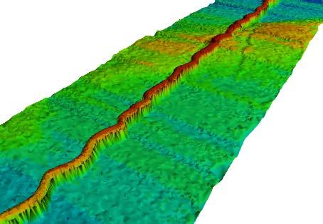
Before shifting
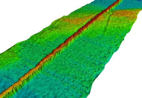
After shifting
