Exporting P1/90 Post Plot Positioning Data
On this page:
P1/90 Export Wizard
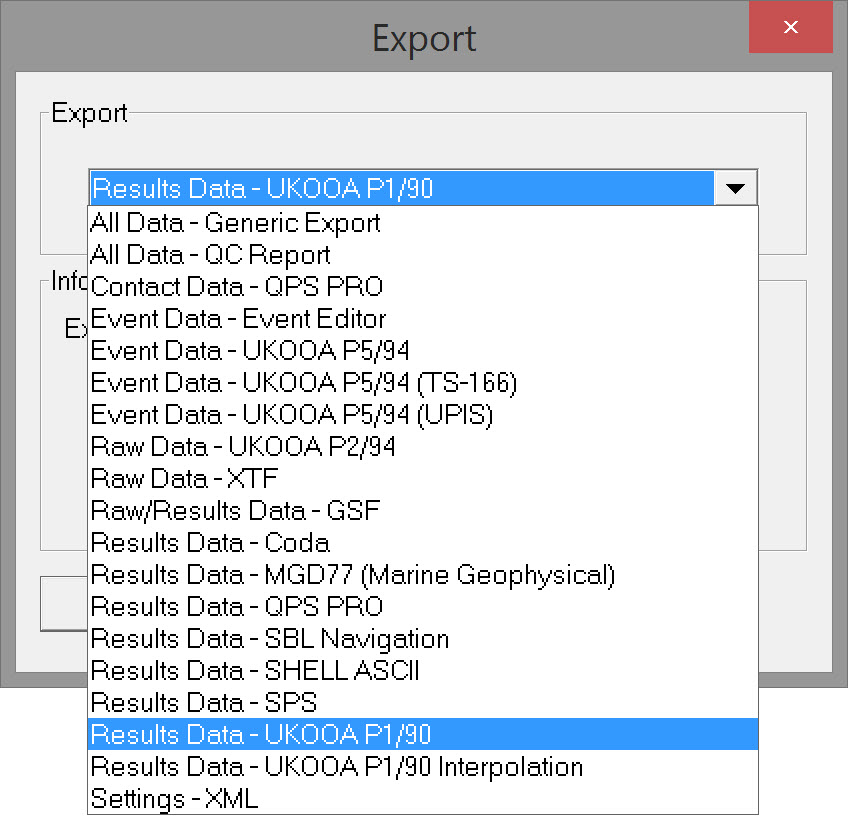
Select 'Results Data - UKOOA P1/90' and click OK to open the export wizard.
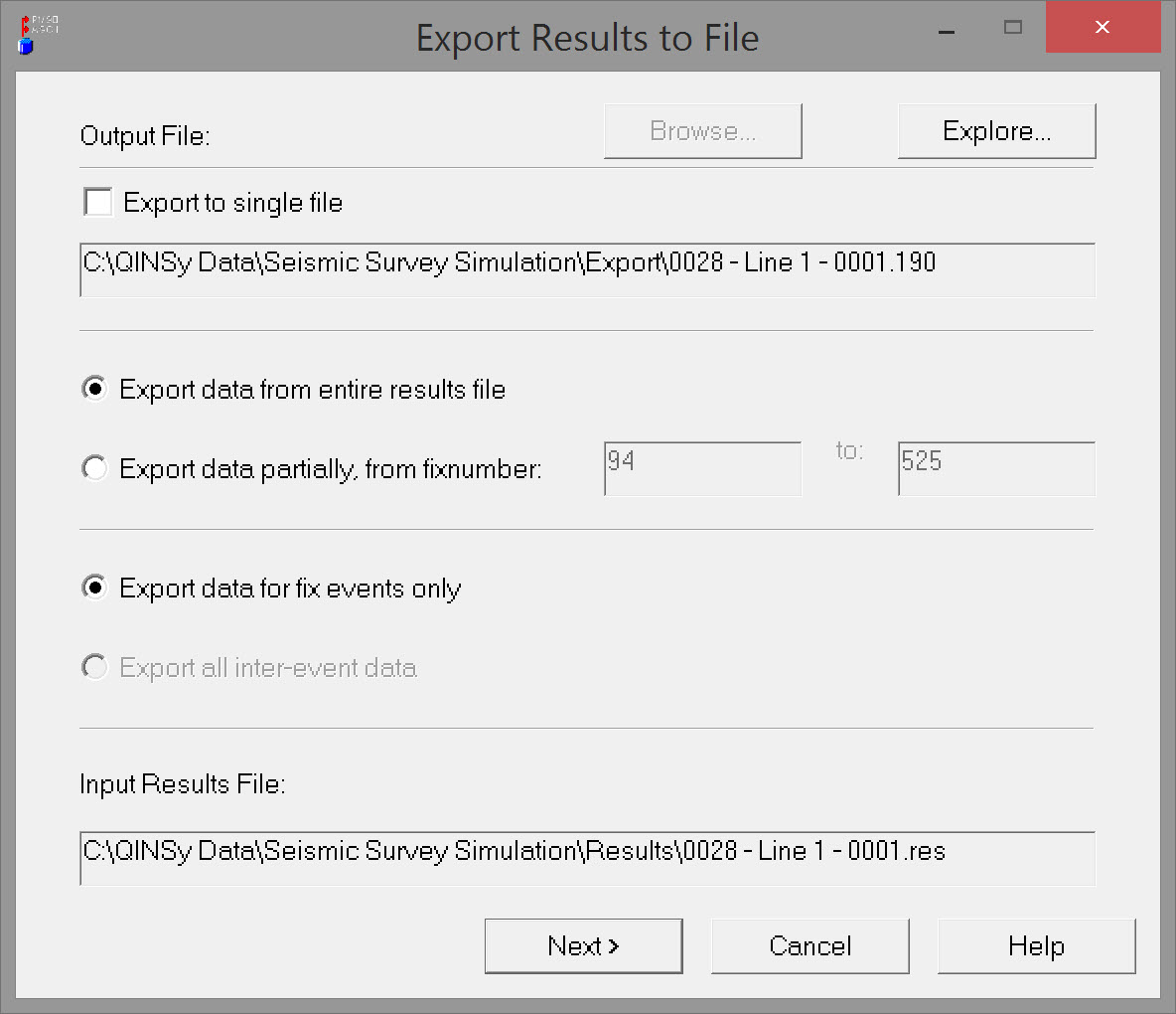
Page 1 - Export Results to File
| Output File | |
|---|---|
| Export to single file | This is an option to combine the P1/90 output of multiple files (selected in the Raw Data Manager) into a single file. Selecting this option activates the Browse button which opens the Project Export folder. Give the combined P1/90 file a name. Clicking on the Explore button also opens the Project Export folder for inspection only. |
| Export data from entire results file | All data is stored in the results file, from the first recorded fix to the last. Exactly what is stored depends on other settings. See below. |
| Export data partially, from fix number | By default the first and last fix recorded in the *RES file are displayed. This option allows the fix range to be modified, which might be the case when fixes on the line run-in and run-out are not required in the P1/90 file. For example the first fix shown in the picture above is 94, but the fix at SOL was 101. The fix at EOL was 500 but another 25 fixes were recorded to accommodate the run-out. |
| Export data for fix events only | *.DB files contain all the raw data recorded and *.RES files contain all positions calculated. This option restricts Fix data output to the subset of positions computed at the time of each shot-point. |
| Export all inter-event data | *.DB files contain all the raw data recorded and *.RES files contain all positions calculated. This option exports all the positions calculated, the frequency of which is based on the triggering system used for the computation cycle. |
| Input Results File | Lists the *.RES file associated with the *.DB file selected in the Raw Data Manager. |
Click Next
Page 2 - P1/90 Node Selection
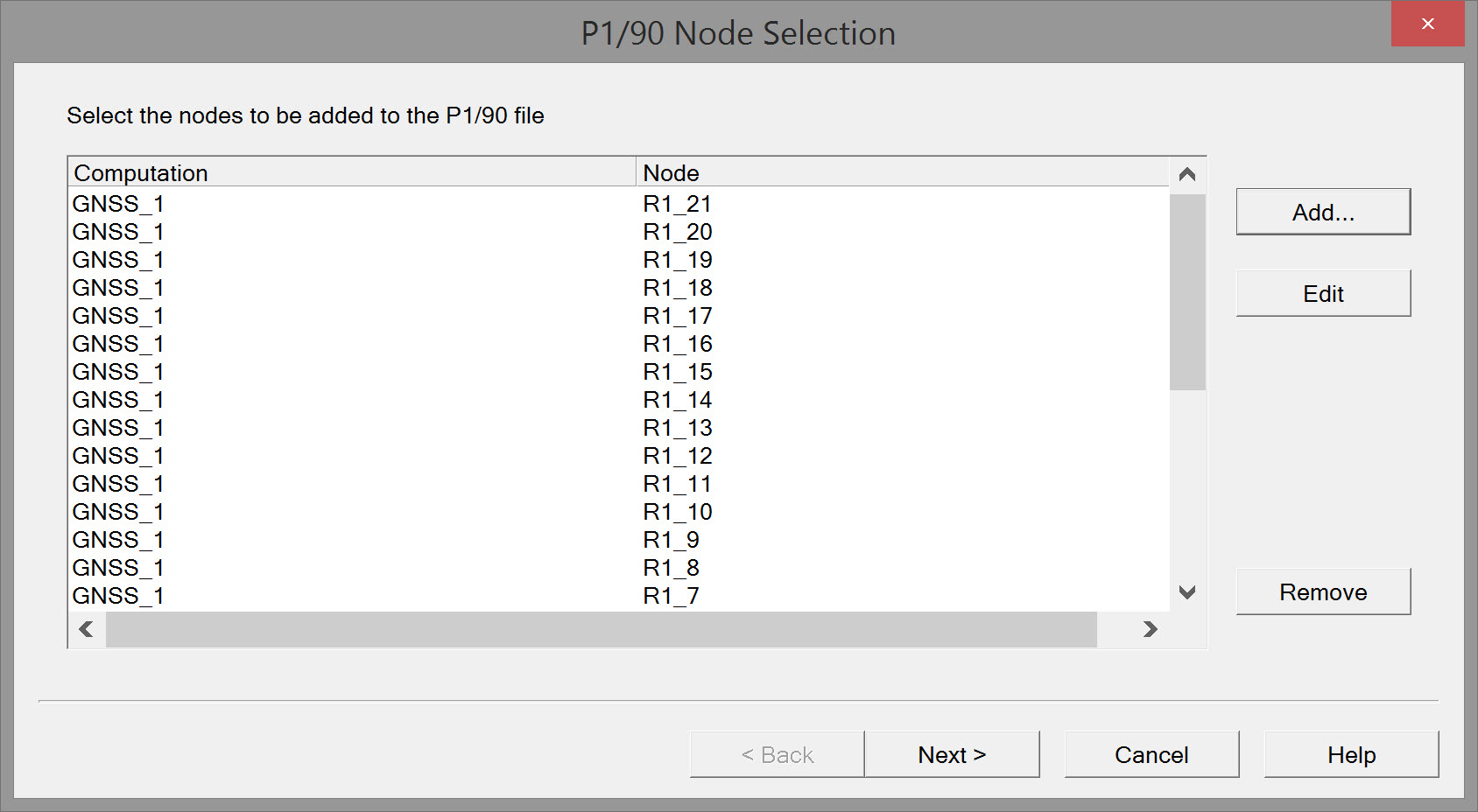
Initially the dialog box is empty. The purpose is to Add all the nodes for which a position is needed in the P1/90 file.
Add - opens the selection window. Simply choose the Computation and Node before pressing OK.

Edit - click on the node to be edited and then click Edit. The same 'Select P1/90 Node' window opens.
Remove - click on the node to be removed and then click Remove.
Order of Node Selection
To facilitate settings later in the wizard, selecting nodes in a particular order is highly recommended. This is best explained with an example:
Example survey spread:
Towing Vessel #1, Gun Array #1, Gun Array #2, Streamer #1, Streamer #2, Streamer #3, Streamer #4, Tailbuoy #1, Tailbuoy #2, Tailbuoy #3, Tailbuoy #4.
Twenty-one 'receiver groups' are defined on each Streamer.
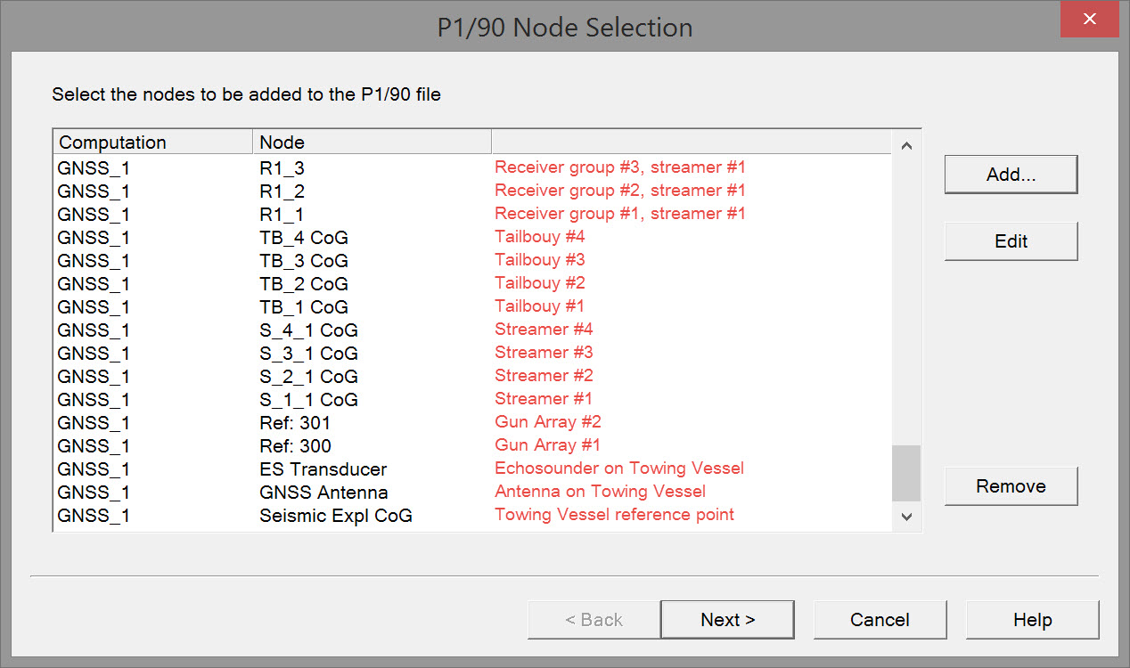
- Select reference node on Towing Vessel #1.
- Select antenna nodes(s) on Towing Vessel #1.
- Select an Echosounder node on Towing Vessel #1.
- Select a node on Gun Array #1, and then a node on Gun Array #2.
- Select the foremost node on Streamer #1 (S_1_1 CoG in the example).
- Select the foremost node on Streamer #2 (S_2_1 CoG in the example).
- Select the foremost node on Streamer #3 (S_3_1 CoG in the example).
Select the foremost node on Streamer #4 (S_4_1 CoG in the example).
Select a node on Tailbouy #1, followed by Tailbuoy #2, Tailbuoy #3 and Tailbuoy #4.
Select the first receiver group node on Streamer #1, (R1_1) followed by the next (R1_2) and so on until all receiver groups (21) have been added for Streamer #1.
- Select the first receiver group node on Streamer #2, (R2_1) followed by the next (R2_2) and so on until all receiver groups (21) have been added for Streamer #2.
Select the first receiver group node on Streamer #3 (R3_1), followed by the next (R3_2) and so on until all receiver groups (21) have been added for Streamer #3.
Select the first receiver group node on Streamer #4 (R4_1), followed by the next (R4_2) and so on until all receiver groups (21) have been added for Streamer #4.
Nodes are added from bottom to top. From bottom upward the final selection should look something like this:

Page 3 - P1/90 Setup Nodes
All the nodes selected on the previous page are listed in the order they were selected. The values initially displayed in columns P1/90 Code, ID 1 and ID 2 will probably not make much sense at all. The task on this page is to assign correct P1/90 codes and IDs to each node.
Having a copy of the P1/90 format description handy will make this job easier.
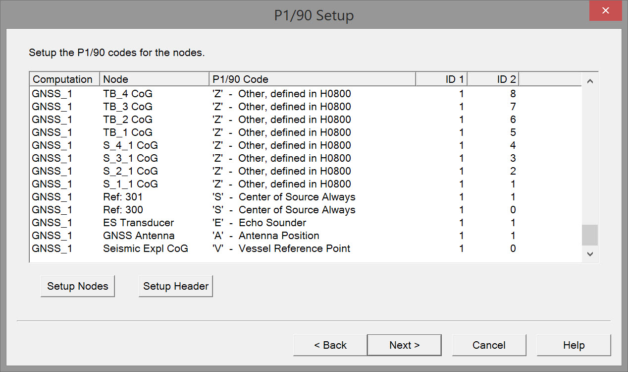
Either double click on a node or highlight a node and press 'Setup Nodes'. The following dialog boxes for different node types (except Gun Reference nodes) require entry of P1/90 codes and IDs.
QINSy supports these P1/90 codes for nodes other than Gun center of source nodes:

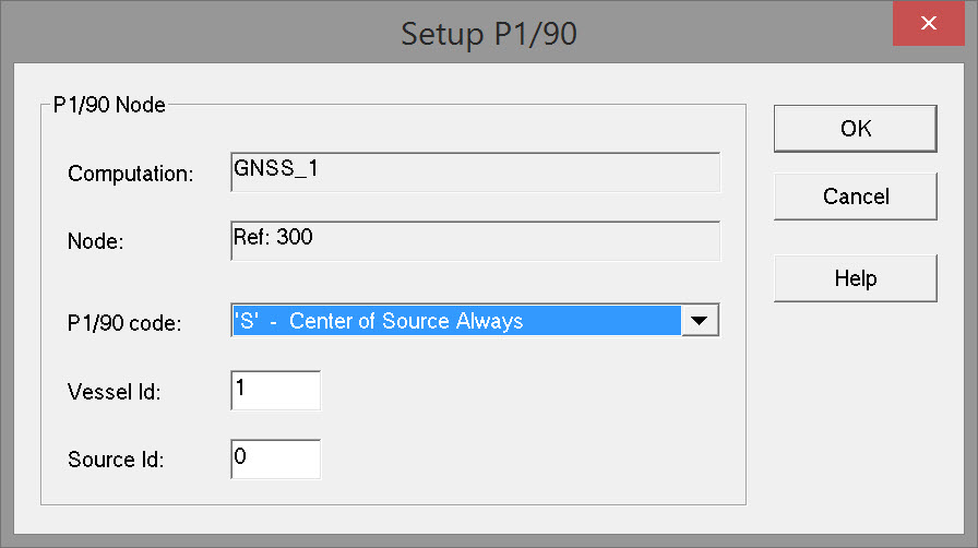
Gun reference nodes have their own selection list:

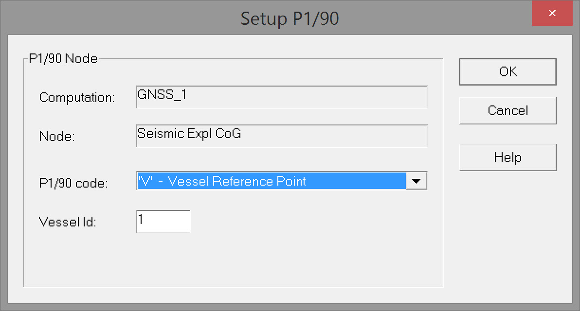
Vessel
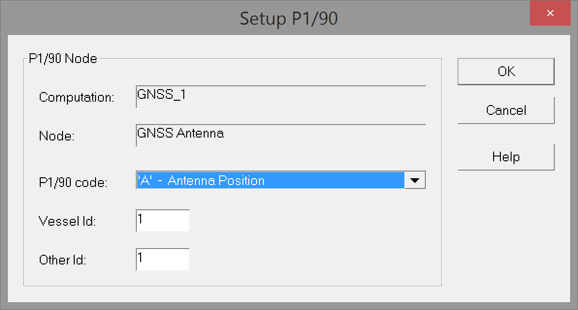
Antenna
Gun
Receiver Group
| P1/90 Node | |
|---|---|
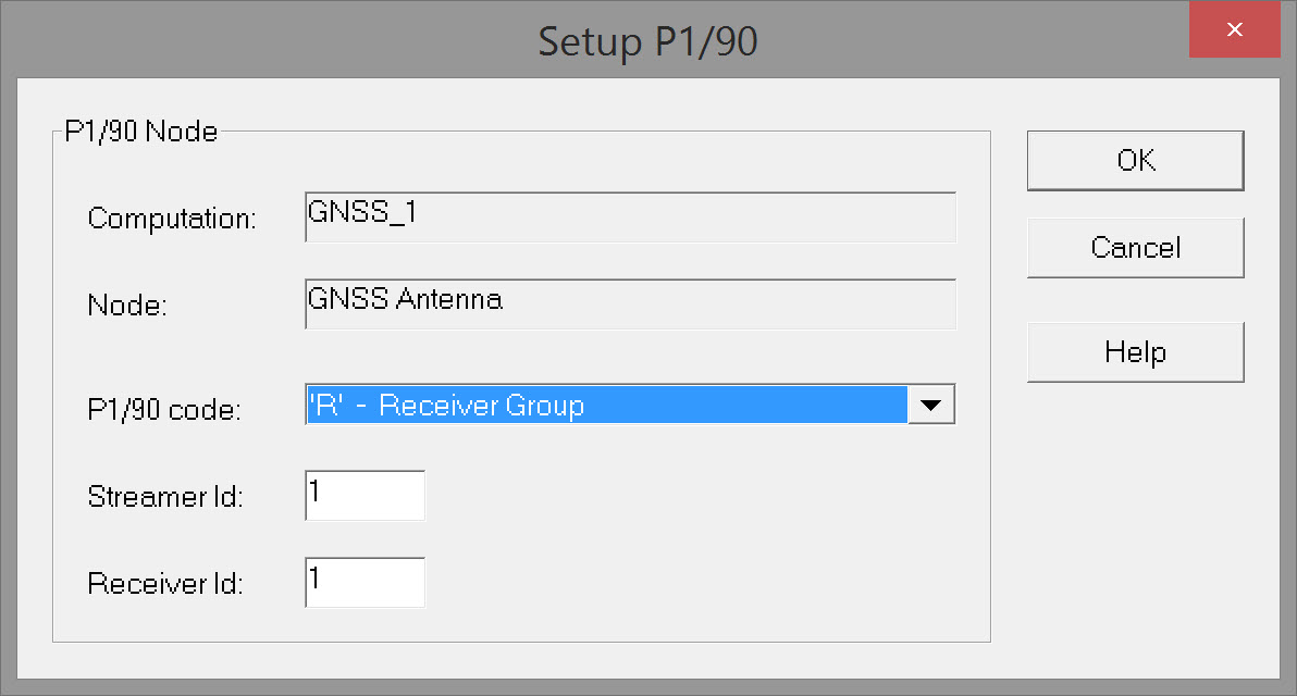
| Computation | Simply shows the computation associated with the node as selected on the previous page of the wizard. |
| Node | Simply shows the node selected. |
| P1/90 Code | The choices in the drop down list are shown above. They do not represent all the codes defined in the P1/90 format description. For example the 'T' = Tailbuoy codes are not used in QINSy but the 'Z' = Other code can be substituted. The P1/90 code options for Gun Array Reference Nodes are different:
NOTE: Receiver Group code is 'R' in QINSy. Elsewhere you may see it as 'G'. |
| Vessel Id. | When the 'V' =Vessel code is selected, only the Vessel Id. text box is available. Typically there is only one towing vessel and the Id. is '1' by default. |
| Streamer Id. | When the 'R' = Receiver Group code is selected, no Vessel Id. is displayed. A Streamer Id. is shown instead. Enter a unique code for each streamer. Note that streamer #10 and above are represented by an alpha code, e.g. A, B, C, etc.. This is because the original P1/90 format did not anticipate more than 9 streamers. |
| Other Id. | When any other code than Vessel is selected, two Id.'s must be entered: the Towing Vessel Id. and the Other Id which refers to there being more than one instance of Antenna, Echosounder, Receiver Group and Other (gun arrays, tailbuoys, front floats, diverters etc.) No P1/90 codes are supported for Streamers and Tailbouys. Therefore use 'Z' records with the precaution that ID 2 must keep incrementing. For example, with 4 Streamers ID 2 could be 1, 2, 3, and 4. With 4 Tailbuoys ID 2 values should be 5, 6, 7, and 8. For streamers, each streamer object will have a unique code but the Receiver Group codes may repeat from one streamer to the next. For example, Streamer #1 may have 100 Receiver Groups with Id.'s #1 through #100. Receiver Group Id.'s for Streamer #2 may also be identified by #1 through #100 as it is their association with Streamer #2 that differentiates them from Receiver Groups associated with Streamer #1. Receiver Groups with ID 10 and greater are identified by an alpha character A through Z. |
Page 3 - P1/90 Setup Header
P1/90 Header Format
Please refer to the UKOOA P1/90 format description for complete details on Header content and configuration.
Each P1/90 file should start with a number of header records which contain information about, and parameters controlling, all of the data records which follow.
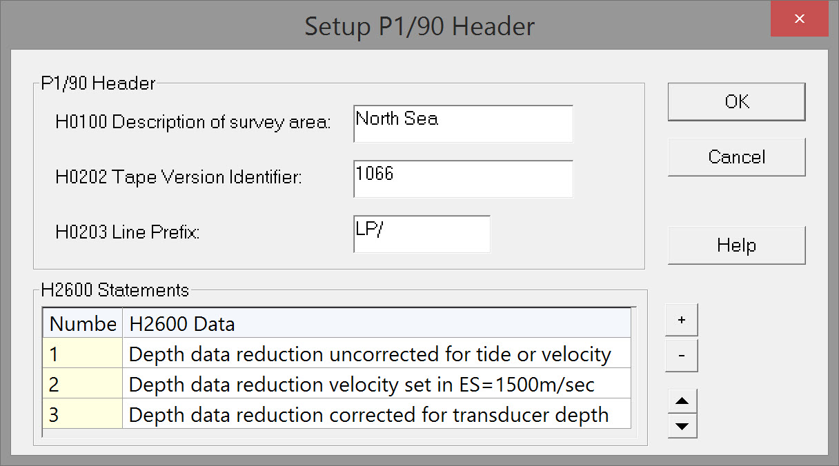
Most Header records are automatically populated with information entered into the Template Database. Some remains to be entered.
| P1/90 Header | |
|---|---|
| H0100 Description of survey area | A description of the survey area occupies columns 33-80 in the H0100 record. Length of entered text should not exceed 47 characters. |
| H0202 Tape Version Identifier | A tape version identifier occupies columns 33-80 in the H0202 record. Length of entered text should not exceed 47 characters. |
| H0203 Line Prefix | A line prefix occupies columns 33-80 in the H0202 record. Length of entered text should not exceed 47 characters. |
| H2600 Statements | |
|---|---|
| Number | Assigned by the software. |
| H2600 Data | Header record type H2600 is a free format statement of any other relevant information such as base station coordinates and geodetic control, description of additional data in receiver group records, survey adjustments done/not done, misclosures etc. |
Page 4 - P1/90 Summary
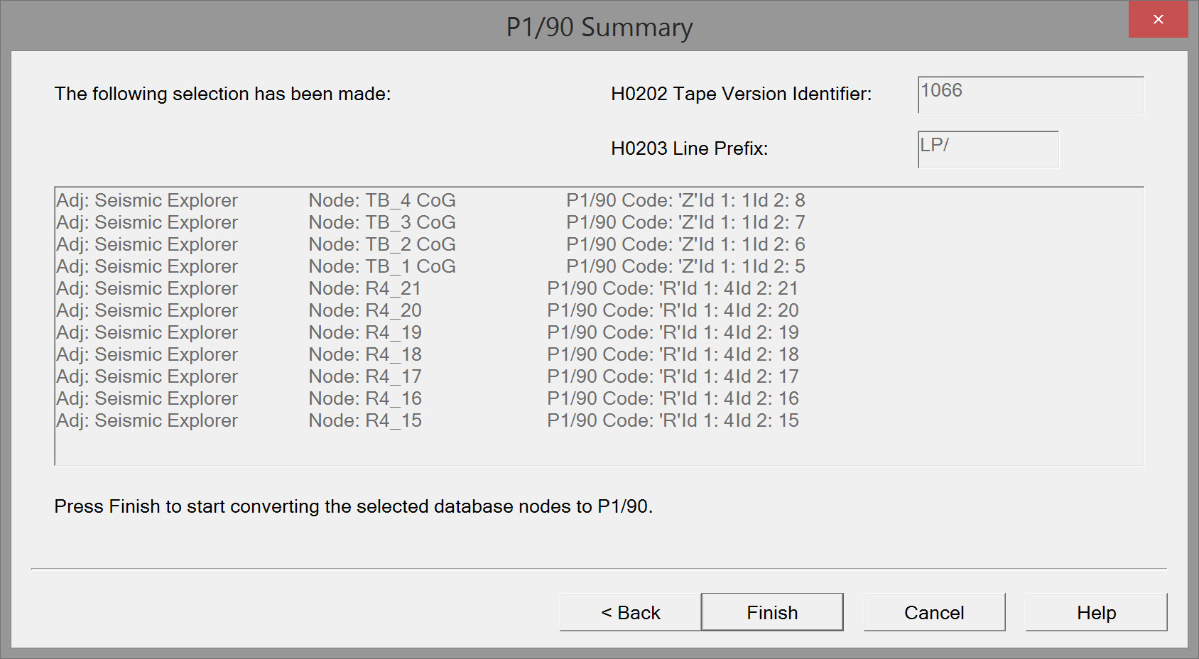
Entered parameter values are presented on the last page of the wizard.
Press 'Back' to modify any entries.
Press 'Finish' to generate the P1/90 file.
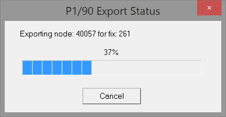
A window pops up to indicate progress of generation.
Return to 43508845.
Return to Exporting Seismic - UKOOA/OGP Formats.
Return to Exporting Towed Streamer Seismic Positioning Data.
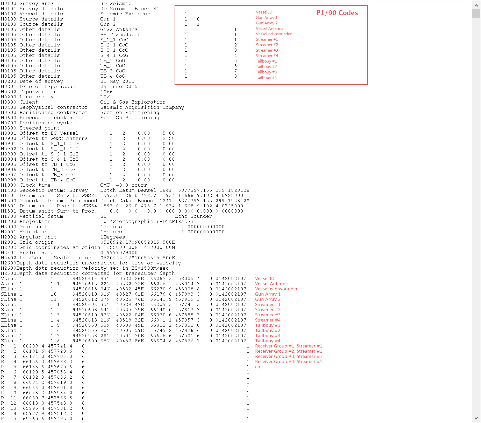
Example of Exported File Header
This is a Header from an export of an entirely simulated 3D survey with 2 gun arrays, 4 streamers and 4 tailbuoys.
Points to note:
- Because QINSy currently does not support a Streamer Object, streamers are defined in H0105 records, Id's 1,2,3, and 4.
- Because QINSy currently does not support a Tailbuoy Object, tailbuoys are defined in H0105 records, Id's 5,6,7, and 8.
Return to 43508845.
History of Format
- P1/90 for Post - plot (processed position) data exchange.
- P2/94 for raw positioning data
These formats were originally developed by UKOOA but ownership was transferred to the International Association of Oil & Gas Producers (OGP) Geomatics Committee in 2006. Changes in acquisition and processing technologies mean the formats have outlived their design life and can no longer support modern acquisition techniques without adaptation. An increasing number of non-standard variations and “add-ons” are being used*. They have therefore ceased to be standards as each user of the formats has modified them differently, to suit their own purpose. In 2011, OGP, the custodian of these formats, brought them up to date to meet the needs of complex seismic acquisition techniques of today and the foreseeable future.
*QINSy supports the original P1/90 format.
P1/90: Uses
- Defined in 1990 to replace the existing P1/84 format.
- Originally intended for use in Offshore and Onshore surveys, but has only really been used Offshore.
- The standard for Marine Post Plot exchange between Positioning and Seismic systems
- Also used for Pre Plot and Bin Centre position exchange
P1/90: Data Content
- A simple header containing survey information, geodetic configuration and a very basic survey spread layout.
- Single Position Records.
- One Record per Position Type, e.g. Source, Vessel,Tailbuoy etc.
- Grid and Geographical Coordinates of the Point.
- Multiple Position Records (Receiver Groups).
- Each Record contains the position of three receiver groups.
- Grid Coordinates only.
P1/90: Data Format
- Data is encoded in an 80 character fixed width ASCII or EBCDIC format, with an optional “CR” and or “LF” character at the end of each record.
P1/90 Format Description
Please find a complete format description toward the bottom of this page, under legacy formats - http://www.iogp.org/Geomatics#2521696-geophysical-operations
Reasons for Updating Formats
- In P1/90, a single digit was used for the streamer number, as 1-9 was considered sufficient in 1990.
- P1/90 defines the streamer number as a single digit. As 10 streamer spreads occurred, this record varied to include A-Z for streamers above 10.
- P1/90 defines shot time to integer seconds (and P2/94 defines it to 1 decimal place).
- P1/90 Grid Position field widths were not defined with enough space to record Feet.
- SEG-P1 had one sentence about geodesy in the documentation. UKOOA - P1 & SPS each had 2 pages in the documentation.
- They were realistically designed to support single cable, single source.
- Most objects are limited to a maximum count of 99.
- Traces are limited to 999.
- They have all been revised to the point where there is no longer a standard.
- Many overlap and as such similar surveys may utilize different variations to provide positional data.
Return to: 43508845
Return to: Exporting Seismic - UKOOA/OGP Formats
