


Volume Calculation
To learn more about the inner workings of the Volume Calculation, please refer to 'How the volume calculation works' in the Help pages.
To visualize the volumetric differences in the 2D Plan View pane, refer to Visualizing volumes

Be patient as it may take quite some time to open!
Here select the area(s) to use as boundaries to the volume calculation.
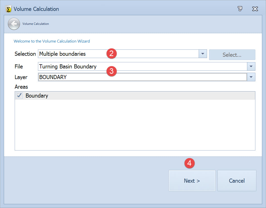

When set to Current Selection the extents defined using the Selection button are used.
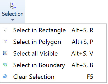
When no selection is made, or when a different selection is needed, click on the 
The Wizard is then hidden until a valid selection is made with the Selection tool.

Then choose the layer and polygon(s) to use. Any checked areas are used for the volume calculation. Use Ctrl+A to select all areas listed.

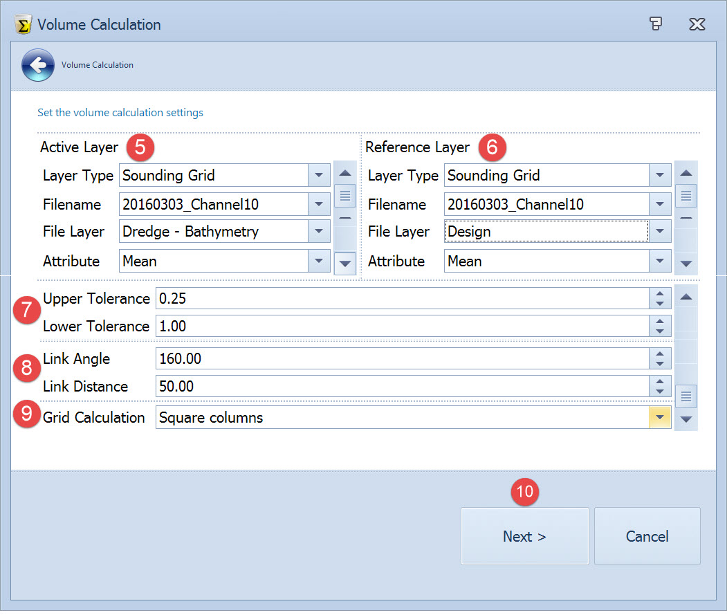
Choose the active and reference layers to use in the volume calculation based on the differences between these two layers.

|
Active Layer |
||
|---|---|---|
|
Layer Type |
Survey |
Select a survey file and the data source. The data source is either/or:
|
|
Sounding Grid |
Select a Sounding Grid file, Layer and Attribute to use as source for the volume calculation.
|
|
|
Design Model |
Select a CAD / GIS file and layer to use as a design model. |

|
Reference Layer |
||
|---|---|---|
|
Layer Type |
Reference |
Specify a single depth to use in the volume calculation. |


|
Link Angle |
This angle control lets you enter the maximum edge angle to use in creating link lines between points. Where the angle between three points along the outside edge of the DTM is greater than the maximum value you enter here, a link line along the opposite side is excluded. The default value of 160° is usually adequate (the maximum value is 179°). With larger angles, undesirable link lines can be created around the exterior of the project. You can correct this situation by reducing the edge angle. |
|
Link Distance |
This distance control establishes the longest distance between triangle points along the edge of a DTM. The value is used to trim the edge of the DTM after all of the points have been linked. If the distance between two edge points is greater than the distance entered here, the link is deleted. Try to set this distance at a value that is a little larger than the longest distance between your exterior points. Note: If there is a "lone" point or an island of points which are farther from the main group of points by a distance that is greater than the maximum edge distance, links will still be drawn so that a single DTM is formed. All 3-D points on a layer are included in the DTM, regardless of the linking parameters. |

|
Square Columns Method |
The square columns method enumerates over all sounding grid cells in the area of interest. For each cell the necessary attribute (mean, deepest or shallowest) is read. At the same location one sample is taken on the reference layer.
In the case that a grid cell is partially in the area of interest, the exact area within the area of interest is calculated and used. The square columns method is a fast and memory friendly approach. |
|
Triangulated Method |
For the triangulated method, both the active and reference layers are triangulated. The resulting triangulated layers are then compared to calculate the volumes.
For a full explanation, also refer to How the volume calculation works. |

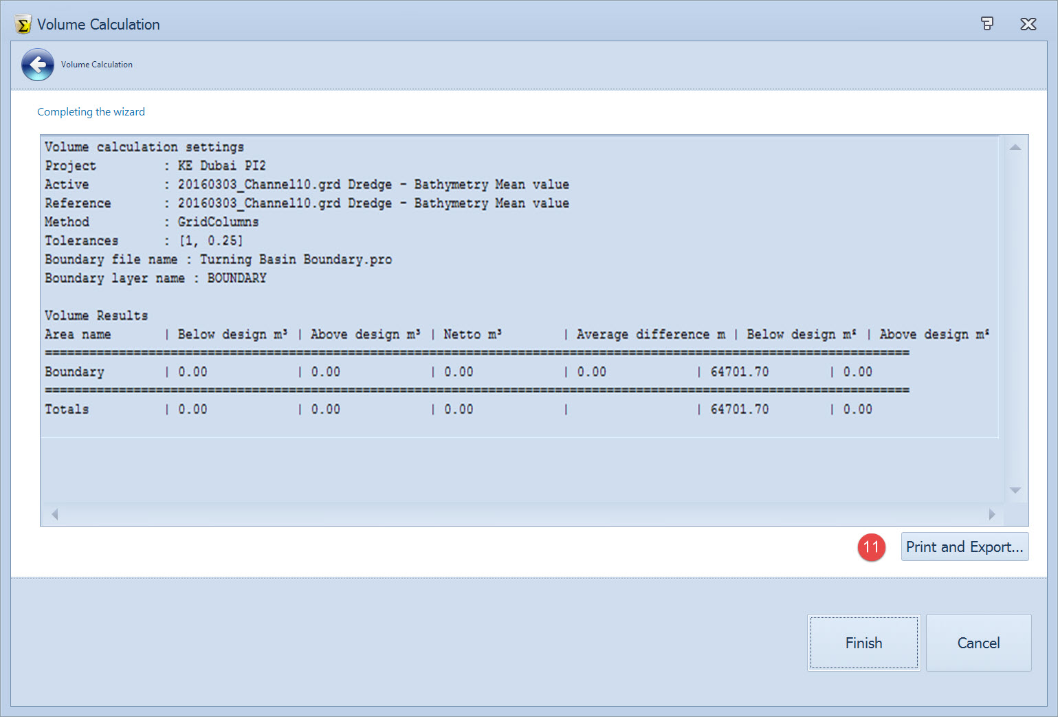
A summary of the volume calculation is shown.

Volume Calculation Report
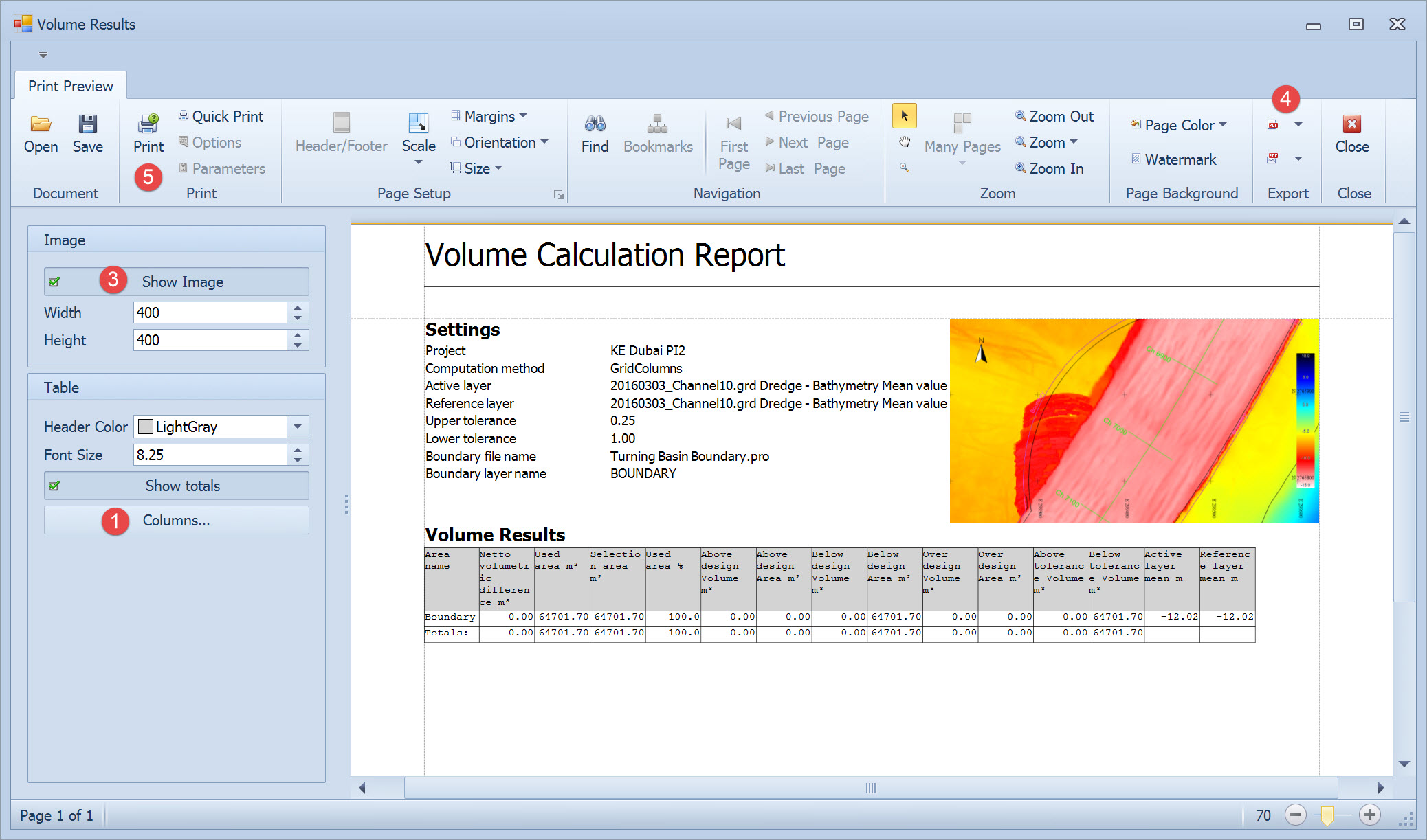
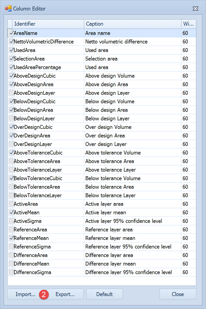
Most of the parameters on the Volume Results page relate to configuring the report and are self-explanatory.
Return to: top of page.
Return to: CSD - Dredging Results.
Return to: Dredge Reporting.