
Planning
The following provides a brief overview of Line Planning.
|
Planning |
|
|---|---|

Line Databases |
Select files and lines to use during a survey. |

Line Planning |
Plan selected lines and see the statistics of the survey. |

Settings |
Additional settings for line planning. |
|
Add mainlines for other objects to use such as ROVs, pipe laying barges or for use on curved rivers. |
|

Additional Terrains |
Select and define terrain models to use as a reference layer in a Profile Display. |

Much more detailed descriptions are available here:
-
In the Controller's Help pages
-
In the Knowledge Base under Session Setup - Planning
The Planning function is used to import line database files (*.QGF) and to organize the use of points (waypoints), lines and polylines (routes).
Any legacy *.PRO files are currently copied to this format; *QGF files are listed along with *.PRO files in the project's \LineData folder.
Line Databases
Use this button to add the line database files needed to run dredging operations.


Browse to the correct folder and select the appropriate *.QGF file in the standard Windows dialog that appears. Add additional files if necessary.
All the waypoints, lines and routes that are defined in the *.QGF file are displayed and they can be turned on/off individually.
Return to top of page.
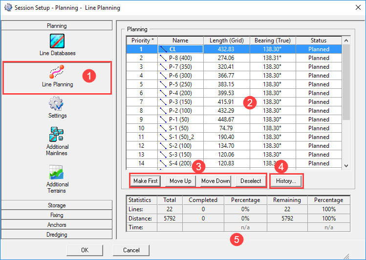
Line Planning


Depending upon settings under Storage - Control, this line order is used during operations.

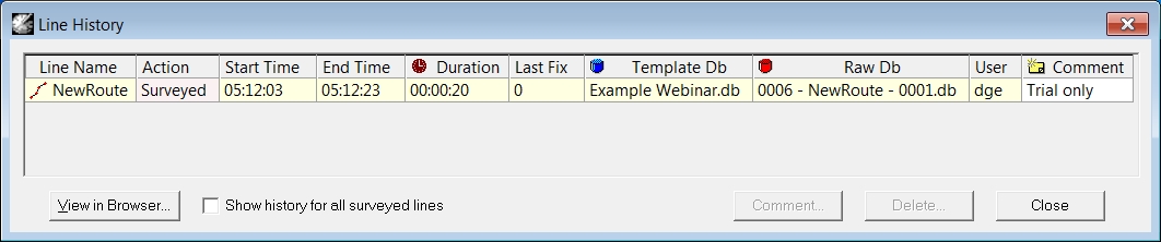
The history is stored in an XML file "Session.History.<Project Name>.xml" which is located in the Project folder \Export\QMS.

Return to top of page.
Settings


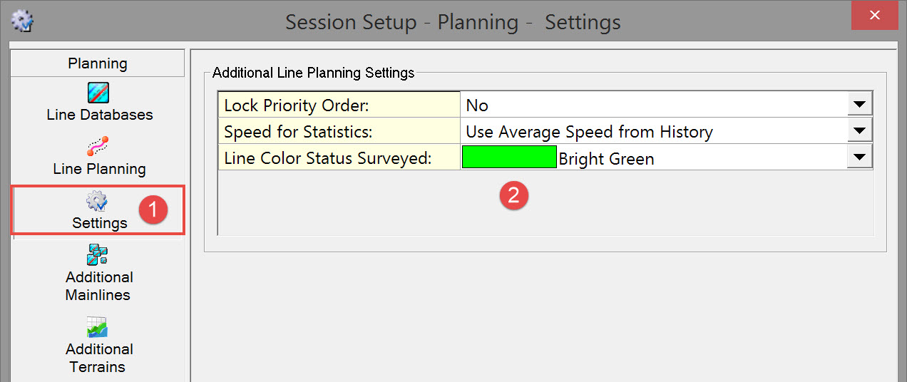

Return to top of page.
Additional Mainlines
Not applicable.
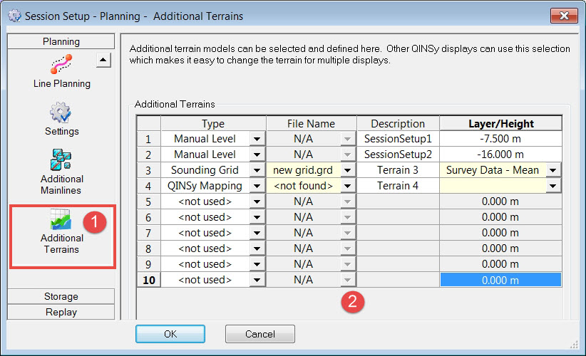
Additional Terrains
An Additional Terrain is defined by a layer from either a grid, a QINSy Mapping *.QGF file or a manual level which can then be selected as the terrain in one or more Profile Displays.
When multiple displays are used, for example with fore, side and aft views then the terrain only needs to be selected once, here in the Session Setup.
For more information see the Profile Display's Select - Terrain menu.


|
Additional Terrains |
|
|---|---|
|
Type |
Three terrain types can be selected:
|
|
File Name |
Select the file name of the Sounding Grid file or QINSy Mapping file. |
|
Description |
The description shown here, will be used in the Profile Display to select the Terrain. Enter a different name if necessary. |
|
Layer / Height |
If a Sounding Grid or QINSy Mapping file is selected, select the Layer that should be used.
|
Return to top of page.
Return to BHD - Session Settings.