
Dredging
The Dredging button is only available:
-
when a Dredging System and a Dredging Tool are defined in the Database Setup and
-
when the Dredging Module is activated on your dongle.
Changes in dredging parameters are permissible during a recording session.
There are five command buttons:
|
Dredging |
|
|---|---|
|
|
Defines the design DTM used in the Navigation, Generic and/or Profile display.
|
|
|
Intrusion Detection (formerly Emergency Hoist) parameters which can be used in the Alert and/or the Generic display.
|
|
|
Production can be used to update the Sounding Grid.
|
|
|
Enter dumping parameters such as material characteristics and densities.
|
|
|
Setting for spill.
|


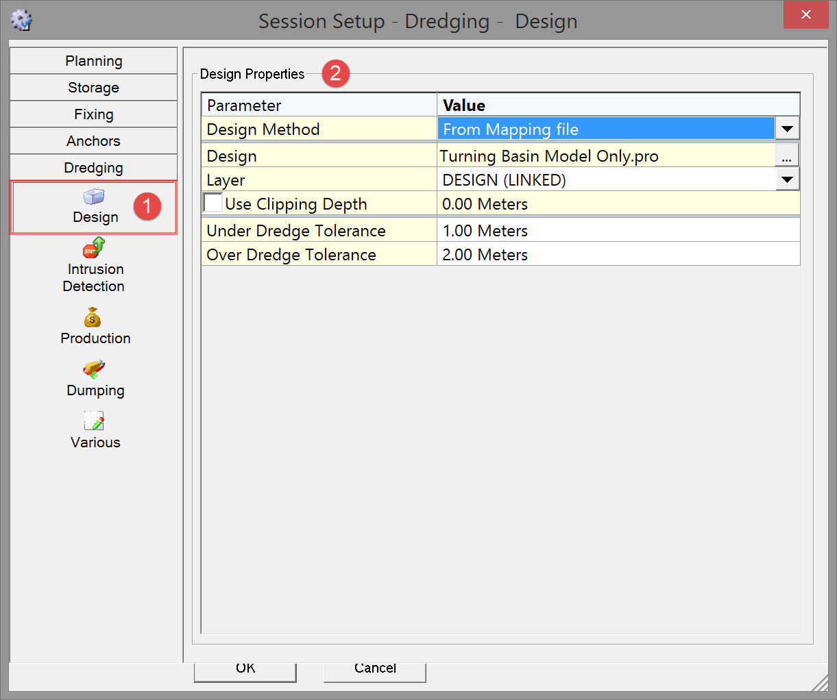
Design


|
Design Properties |
|
|---|---|
|
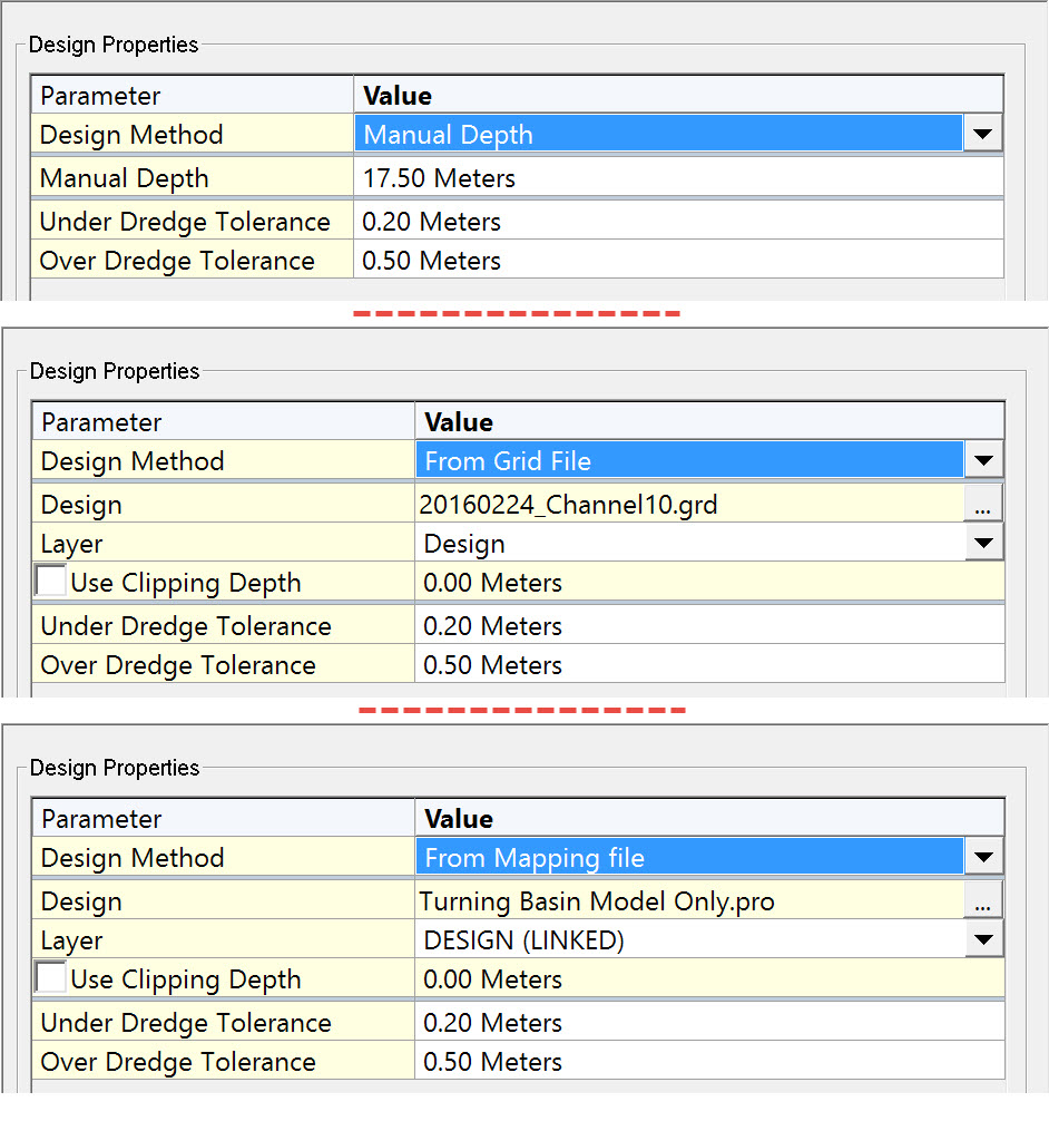
Design Method |
For the design different options can be chosen:
|
|
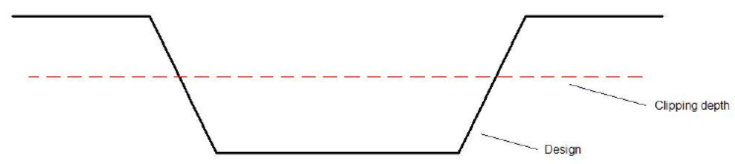
Use Clipping Depth |
This option is only available when From Grid file or From Mapping File is selected as Design Method.
Clipping depth is used when removal of material is done in layers. The design is clipped to the depth entered and the dredger uses it to control cut depth for that pass.
|
|
Dredge Tolerances |
Enter upper and lower dredge tolerances These values are relative to the design. Enter positive numbers for both. |
Return to top of page.
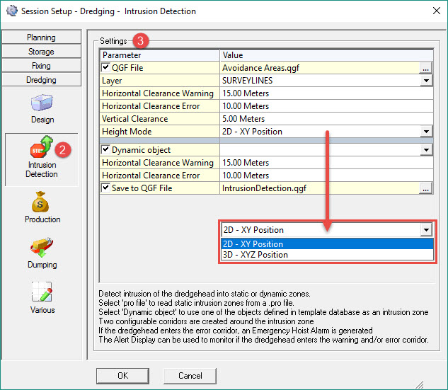
Intrusion Detection
A dredger may be allowed to enter a certain zone, but because of safety issues, it's dredging tool may not be permitted too close to the seabed where seabed objects could be damaged. For example live gas pipelines on the seabed are a hazard. Intrusion Detection functionality raises an alarm when restrictions have been violated. Two types of alarms are generated: a Warning and an Error.
Online the program uses this area, along with the Horizontal Clearance Warning and Horizontal Clearance Error distances to create intrusion corridors around the area. In effect these Horizontal Clearance distances create a Warning and an Error corridor around the avoidance area.
When the vertices of these polygons are given height, the Vertical Clearance works in conjunction with the horizontal and a Height Mode setting of 3D XYZ Position to extend Warning and Error detection to 3D.
The ongoing status of this so-called emergency hoist system is visualized in the Generic Display and Alert Display.
In addition this detection system is employed to protect other dynamic objects in the vicinity. For instance to prevent a backhoe from hitting a barge.
The hull (areal extent) of an object defined in the template database acts as an avoidance area in much the same way as an avoidance area defined by a polyline.

|
Settings |
|
|---|---|
|
Pro File |
Check this box in order to load to a *.QGF file containing avoidance areas. Use the browse button to select the correct file.
When defining a closed polyline for an entire area (2D) the last point of the poly line must be identical to the first. Note that a closed polygon is always checked in 2D mode only, ignoring the dredge head height.
|
|
Layer |
Select the layer containing the avoidance polylines. |
|
Horizontal Clearance Warning |
Every calculation cycle QINSy checks whether the dredge head(s) is/are located in proximity to the predefined avoidance areas.
|
|
Horizontal Clearance Error |
If the horizontal distance between the avoidance area and the dredge head is smaller than this distance, the Intrusion Detection Error (e.g. Emergency Hoist) alert is raised. |
|
Vertical Clearance |
Minimal vertical distance between dredge head and avoidance poly line.
|
|
Height Mode |
Choose between:
|
|
Dynamic object |
Check this box to use the hull of an object defined in the Database Setup as the avoidance object. Use the drop down menu to select the desired object. |
|
Save to QGF File |
Check this box if you wish to save the warning and error area polygon to a *.QGF file. This way the areas can be visualized in, for example, the Navigation Display.
|
Return to top of page.
Production
Most of the parameters presented in the Production dialog target other types of dredging, e.g. cutters and trailing arm hopper dredges.
For backhoe precise dredging quantities of materials dredged are obtained from pre- and post-dredge bathymetric survey data.
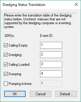
Another measure of production is hopper Trip Volume entered manually and incremented via the dredge Status flag received from either the dredge computer or QINSy Eventing System. For example:
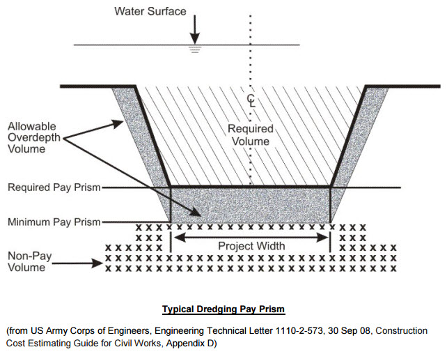
Total dredging quantities comprise required volume, overdepth quantity dredged, and incidental non-pay yardage dredged.
Excavation production rate.
Click to expand...
According to US Corps of Engineer documentation, excavation production is the quantity of material removed per unit of time.
The dredge excavation production rate consists of digging the material and loading scows.
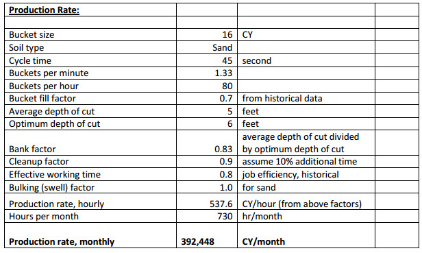
The average excavation yardage per hour is calculated using the following factors:
-
Type of material to be excavated. The estimator must evaluate the type of material predicted for the site. The type of material determines the bucket size and production characteristics. Smaller dredges typically do not dig dense materials.
-
Size of clamshell bucket. Bucket sizes can vary widely, from a fraction of a cubic yard to many cubic yards. An optimum bucket size should be chosen for the job at hand, from the buckets available to the contractor.
-
Bucket fill factor. The bucket fill factor is based on the type of material. For example, mud excavation is more efficient because of its density and tendency to completely fill the bucket. Sand, on the other hand, is less cohesive, and is easily displaced during excavation.
-
Thickness or bank height of material. To be efficient, the clamshell must dig a sufficient depth of material to fill the bucket on each cycle. This factor is related to the height of the bucket, the bucket falling velocity, and other aspects.
-
Bank factor. The bank factor is the ratio of the actual conditions to the optimum bank conditions. For example, if only 4-ft of material is available for a bucket requiring 8-ft, the bank factor would be 0.50.
-
Estimated bucket cycle time. This factor is dependent upon dredge size, operating characteristics, and operator efficiency. A complete cycle is defined as the lowering of the open bucket to the ocean floor, mechanical digging of material, closing the bucket, raising the filled bucket, and positioning the bucket for release into a waiting scow.
-
Effective working time. As stated above, effective time is time spent in actual dredging operations. Often based on historical data, this percentage is multiplied by 730 hours to give a resultant operating time per month. Lost time due to major repairs, vessel alteration, cessation of work, and collisions, is not typically used in dredging time calculations.
-
Site specific multiplier. This is a factor to be used for miscellaneous site specific adjustments, if any. This factor is based on estimator judgment derived from past similar jobs.
-
Cleanup factor. The estimator must account for additional time necessary to perform cleanup dredging to remove minor shoals left inside pay prism, that have been detected by an post-dredge survey. The dredging of these shoals requires additional time that is not very productive.
Example:
The Eventing System could be used to keep a log of number of trips and volume per trip.
|
Trip Volume |
|
|---|---|
|
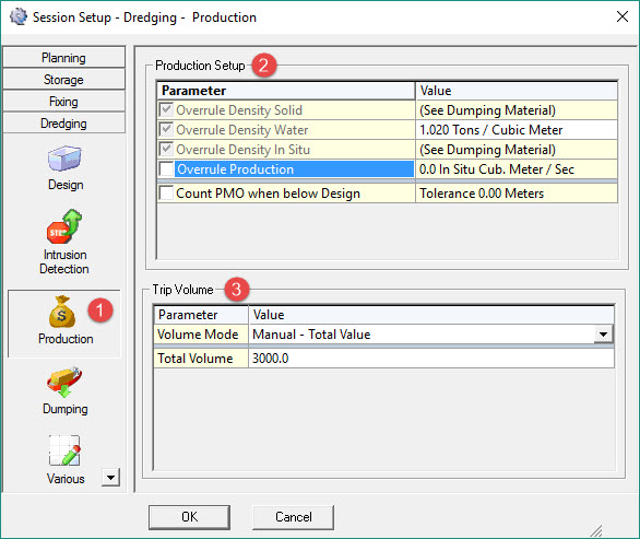
Volume Mode |
Manual - Total Value - This volume will be used to update the sounding grid when the dumping is done and will overrule the production that was calculated during the dredging operation.
|
|
Total Volume |
Enter the volume when Volume Mode is set to Manual - Total Value. |
|
Bay x Volume |
Enter the volume when Volume Mode was set to Manual - Per Bay. |
Return to top of page.
Dumping
Computer models are used to predict the dispersion of dredged material during dumping.
The behavior of dredged material during disposal/dumping is assumed to be separated into three phases:
convective descent: during which the disposal cloud falls under the influence of gravity and its initial momentum is imparted by gravity
dynamic collapse: occurring when the descending cloud either impacts the bottom or arrives at a level of neutral buoyancy where descent is retarded and horizontal spreading dominates
passive transport-dispersion: commencing when the material transport and spreading are determined more by ambient currents and turbulence than by the dynamics of the disposal operation.
The dumping parameters entered here influence the dumping process and production values, including updating of the sounding grid to reflect the dump.
In fluid dynamics, the drag coefficient (commonly denoted as: cd, cx or cw) is a dimensionless quantity that is used to quantify the drag or resistance of an object moving through a fluid environment, such as air or water.
It is used in the drag equation, where a lower drag coefficient indicates the object will have less aerodynamic or hydrodynamic drag.
The drag coefficient is always associated with a particular surface area and reflects the net force in the direction of flow due to pressure and shear stress forces on the surface of the object.
Drag Along and Across coefficients are used in determining the dynamic settling location of the dump.
The user can empirically determine these coefficients by comparing the actual (surveyed) dump position versus the theoretical position.
Set Drag Along and Across coefficients to 1 if they are unknown.
The densities should be absolute. The relative density is derived by subtracting the water density.
Solid density: Density of the dry material.
In Situ density: Density of the material once suspended in water. This occurs when the material is dumped.
By default keep values equal.
If In Situ Density is smaller than Solid Density then the volume used to update the sounding grid will be larger than the entered trip volume.
|
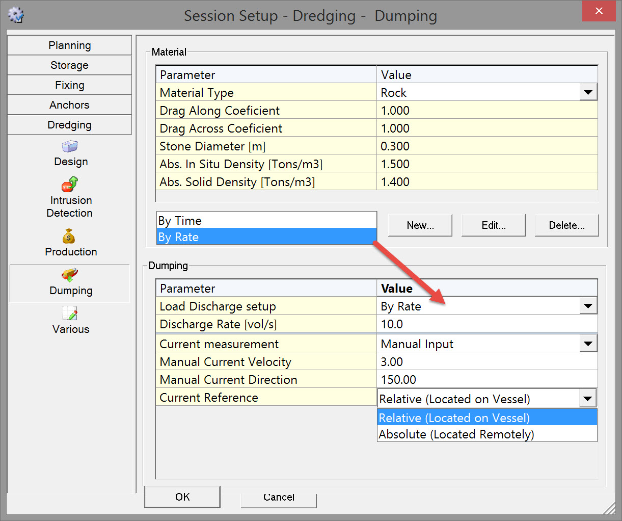
Material |
|
|---|---|
|
Material Type |
Choose the material which will be discharged. New materials can be added to the drop down list by selecting the New button below the dialog. |
|
Drag Along Coefficient |
The Coefficient for the material depends on the particle shape and can be determined empirically in a laboratory.
|
|
Drag Across Coefficient |
The Coefficient for the material depends on the particle shape and can be determined empirically in a laboratory.
|
|
Stone Diameter |
Enter a value in meters. |
|
Abs. In Situ Density |
The density can be determined empirically in a laboratory. |
|
Abs. Solid Density |
The density can be determined empirically in a laboratory. |
|
New |
Add a new Material Type and enter its properties. This Type can then be selected from the drop down list. |
|
Edit |
Edit an existing Material Type and its properties. |
|
Delete |
Delete an existing Material Type and its properties. |
|
Dumping |
|
|
Load Discharge setup |
By Time - A dump bay is emptied in a certain time.
|
|
Discharge Time |
Enter a dumping time in seconds. This is the time it takes for the vessel to empty its bay.
|
|
Discharge Rate |
Enter a dumping rate in volume per second.
|
|
Bay x Opened/Closed |
Select whether bay doors are used in this process. If so, select whether they are open or closed. |
|
Current measurement |
Select whether the current measurement is done with an instrument such as DVL (as entered in Database Setup) or that a manual value will be given. |
|
Manual Current Velocity |
Enter a value. |
|
Manual Current Direction |
Enter a value. |
|
Current Reference |
Relative (Located on Vessel) - The measurement is done on the vessel. The current is corrected for vessel movement.
|
Return to top of page.
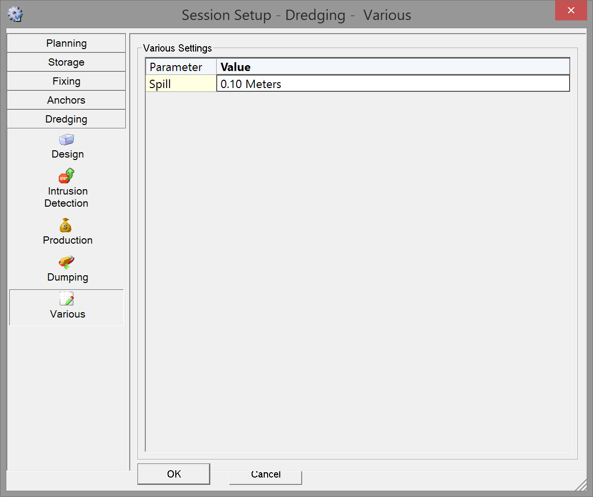
Various
|
Various Settings |
|
|---|---|
|
Spill |
Enter a spill value in meters. This value will be subtracted from the dredged depth in the Sounding Grid.
|
Return to top of page.
Return to BHD - Session Settings.