This How-to document explains how to create a geoid file in the *.bin format (Qinsy 9.8 and later versions). Or how to add an existing *.bin file.
We suggest to look at the following How-to before continuing here:
Create a Geoid Model
In order to create a BIN geoid file, a geographical grid is required.
-
Make sure the data you want to use contain:
-
Latitude
-
Longitude
-
Height (difference between ellipsoid datum and vertical datum)
-
The following formats are supported:
-
ASCII (.txt)
-
ARC ASCII (.asc)
-
ISG (.isg)
-
Trimble GGF (.ggf)
Steps to follow :
-
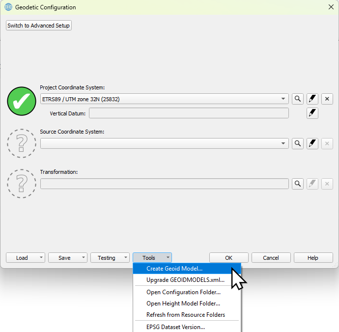
Open the Geodetic Configuration

-
Select Create Geoid Model… from the Tools menu
-
Automatically Windows Explorer will be opened, where you can select your file.
Make sure that your file has an original and clear name. Because the bin file will get the same name as your *.txt file e.g. It’s possible later to change the name as how the geoid will show up in the UI, but this won’t change the name of the saved *.bin file and wkt file.
-
Select the file and click on open.
-
Select the appropriate file format.
-
If the file format is an ASCII Text file, select Configure …
(if it’s one of the other file formats, the other fields should have been filled automatically)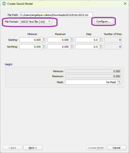
-
Enter here which column is which field and click on OK.
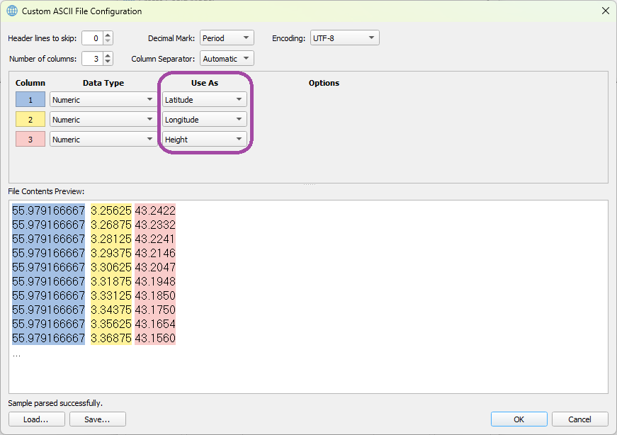
More information about the Custom ASCII File Configuration can be found here: https://qpssoftware.scrollhelp.site/qimera/qimera-custom-ascii-file-configuration-dialog
-
The other fields will be filled in automatically.
-
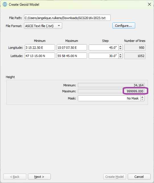
When a ‘Mask’ value is being used in the file, the Minimum or Maximum value will contain this mask value.
-
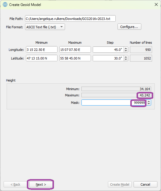
You have to correct for this, to enter this value as ‘Mask’.
-
The value should be changed then into the corresponding Minimum or Maximum.
-
If the values look OK now, click on Next.
-
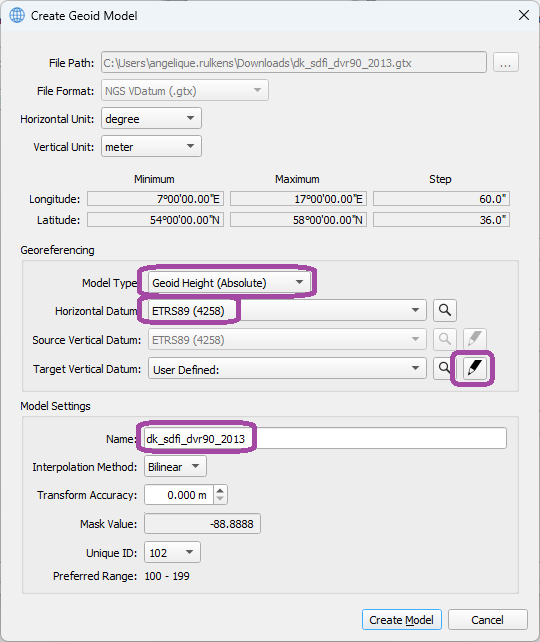
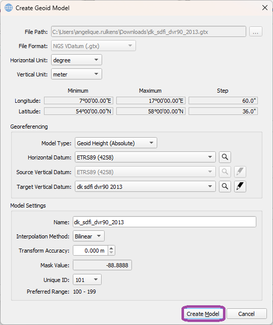
Under Georeferencing, select the Model type, this can be absolute (separation values are referenced to a Datum) or Relative (separation values are referenced to another offset model)
-
Select the Horizontal Datum (the datum on which the separation model was created).
-
Select the Target Vertical Datum.
-
Under Model Settings, it’s possible to change the name (this name will be shown in the geodetic user interface).
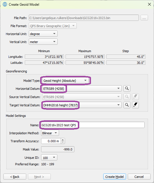
Information about all items here can be found under: Geoid Model Parameters Dialog
-
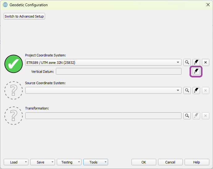
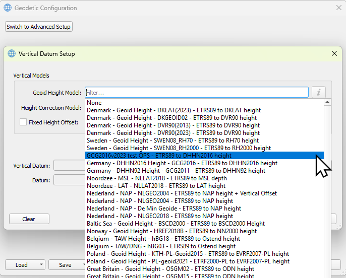
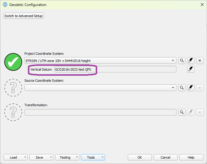
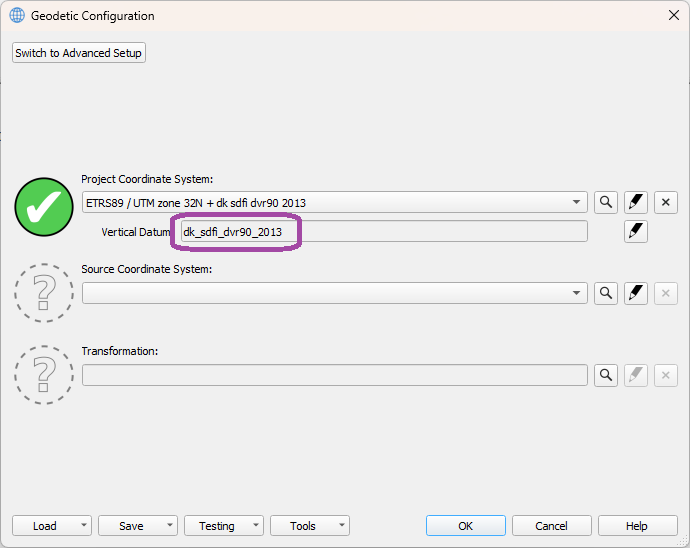
Now the created geoid model, can be selected under Vertical Datum.
Add a Geoid Model
With the same tool, it’s possible to add geoid models that are in a default supported file format and converting them into a QPS binary geoid model.
Default Supported File Formats
-
QPS binary geoid (.bin)
-
NGS Geoid (.bin)
-
NGS VDatum (.gtx)
-
NRCan Geoid (.byn)
-
Binary Surfer Grid (.grd)
Steps to follow:
-
Open the Geodetic Configuration
-
Select Create Geoid Model… from the Tools menu
-
Automatically Windows Explorer will be opened, where you can select your file.
-
Select the file and click on open.
-
Check if all the parameters look OK.
Information about all items here can be found under: Geoid Model Parameters Dialog
-
Under Georeferencing, select the Model type, this can be absolute (separation values are referenced to a Datum) or Relative (separation values are referenced to another offset model)
-
Select the Horizontal Datum (the datum on which the separation model was created).
-
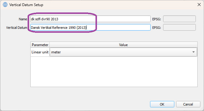
Select the ‘Setup’ icon behind Target Vertical Datum to define your Vertical Datum.
-
Under Model Settings, it’s possible to change the name (this name will be shown in the geodetic user interface).
-
Enter a name for your Vertical Datum Setup.
-
Select Create Model.
-
Now the created geoid model can be selected under Vertical Datum.
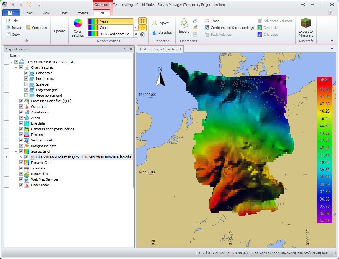
Check the Geoid Model in Survey Manager
After creating the geoid model, it’s possible to visualy check it in the survey Manager.
Steps to follow:
-
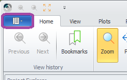
Open the Survey Manager.
-
Select the File Tab.
-
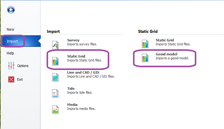
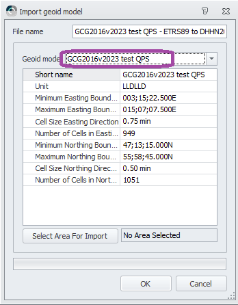
Select from the Import Menu → Static Grid → Geoid model.
-
Select the newly created Geoid Model.
-
Now the Geoid Model is shown as a static grid in the Survey Manager