FMGT - Source Files
The Source Files tab of the Source Files Panel shown in the Source Files Tab figure below shows all of the files currently loaded into a project. If you have loaded directories of files, the directory hierarchy will be preserved in the Source Files Tree.
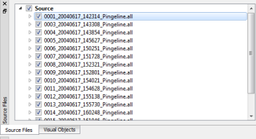
Source Files Tab
When you select a node in the Source tree view, the related nadir and swath track lines will be highlighted in the Map View. This makes it easy to see where a line is spatially in your scene. Also, when you select a line by clicking in the Map View, the corresponding source file node will be highlighted in the tree view. This makes it easy to correlate lines back from the Map View to the Tree View.
The checkbox for a source file node controls three key behaviours. The first is whether this line will be included for any type of processing requested by the user. If the line is unchecked, it will be skipped during any processing. The second behaviour is that the checkbox controls whether the associated track lines are visible or not in the tree view. The last behaviour is that the checkbox can easily add/remove lines from an existing mosaic. If you want to remove a line, simply uncheck it in the tree view and "refresh" the desired mosaic using the context menu for that mosaic or the "refresh" toolbar button for the currently selected mosaic.
There are many "helper" context menu items that can be used to automatically check/uncheck files in the source tree. These are discussed in the Root Node section.
Source File Metadata
When you click on the caret next to a source line, you display the metadata associated with a specific file as shown in the Source File Metadata figure. The metadata provides an easy way to debug files that have been problematic during processing stages. For example, you may be missing backscatter information, have no valid navigation or the file may contain only a few pings of data.
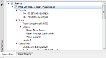
Source File Metadata
The Extents node displays the navigation 2D extents of the data. This information was created during indexing of the file and may not include the outer edges of the swath.
The Sonar node has information on sonar type, sonar modes and number of heads. The Modes node displays all of the available logged modalities of the sonar.
The Datagrams node displays the count of each datagram type present in the source file.
Source File Context Menu – Root Node
When you right click on a source file node, or the source root node, you will get the source file context menu. Different parts of the menu will be highlighted based on the node type you clicked on and other states of your project.
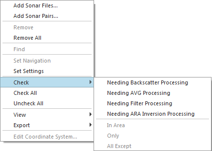
When right-clicking on the root node of the source tree, you will get the menu options shown in the Source Root Node Context Menu figure.
The Add Sonar Files menu option will bring up Add Source Files Dialog.
The Add Sonar Pairs menu option will bring up the Add Sonar Pairs Dialog.
The Remove All option will remove all source files from the project. You will be prompted to confirm this option before proceeding.
Source Root Node Context Menu
The Set Settings option will pop up a dialog to choose the Processing Parameters for all lines under the source menu. See Set Settings Dialog figure below.

Set Settings Dialog
The Check menu option has a sub-menu that allows you to check files based on their processing state. You can also have FMGT check all lines that are currently within a currently selected area. See the Tool Bar section for a description on to do an area-based selection in FMGT.
The Check All option will check all files in the project.
The Uncheck All option will uncheck all files in the project.
The View and Export sub-menus will be disabled as they are specific to a source file node and not the root node.
Source File Context Menu – Source File Node
When you right-click on a specific sonar node, the menu options in the context menu will adjust accordingly as shown in the Source File Node Context Menu figure.
The Remove option will remove this particular file. You will be prompted to confirm the removal request.
The Find option will open the Select Source File dialog to allow you to find the source file if the source file has been moved.
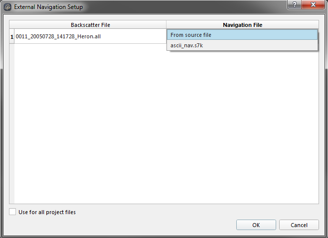
The Set Navigation option will open the External Navigation Setup dialog, shown in the figure below. This feature will allow you to select a different navigation file to replace the navigation from the source file. This external navigation file can be added from the FMGT - File Menu -> Add Nav Files, or by using the default navigation from the source file. If you have one navigation file that spans the entire length of the survey project, you can select the Use for all project files to use the navigation file for all survey project lines. This will match the navigation file to the backscatter file by timestamp.
The Set Settings option will allow the Processing Parameters to be set for the selected line.
The Check sub-menu will allow you to check only this file or all except this source file. This is handy when you want to eliminate a file that is causing problems from the processing pipeline.
The View sub-menu shown in the Source File Node - View Sub-Menu figure allows you to activate plot or waterfall dialogs for viewing of particular navigation or backscatter data within a file. It activates the same controls as described in the Tools Menu.
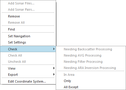
Source File Node Context Menu
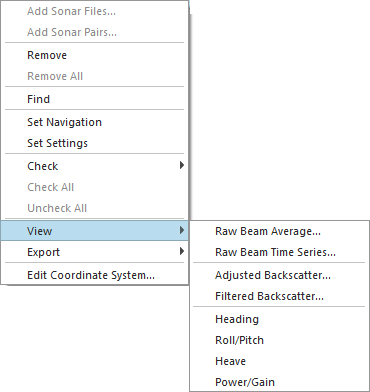
Source File Node - View Sub-Menu
The Export sub-menu allows you to export data related to a specific file as shown in the Source File Node - Export Sub-Menu figure.
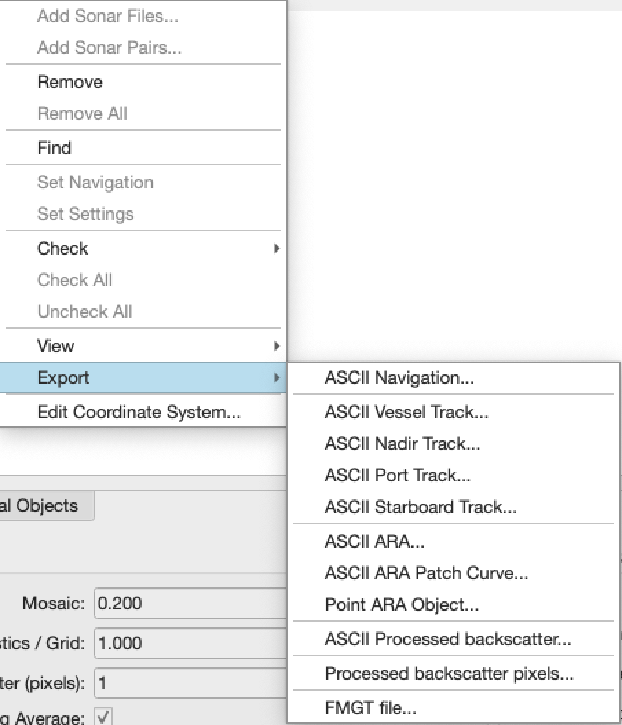
Source File Node - Export Sub-Menu
The ASCII Navigation option will export a text file containing the Time, Longitude, Latitude, Roll, Pitch, Heading and Heave for each ping.
The ASCII Vessel Track option will export a text file containing the Easting and Northing of the vessel for each ping.
The ASCII Nadir Track option will export a text file containing the Easting and Northing of the nadir beam for each ping.
The ASCII Port Track option will export a text file containing the Easting and Northing of the port most beam for each ping.
The ASCII Starboard Track option will export a text file containing the Easting and Northing of the starboard most beam for each ping.
The ASCII ARA option will export a text file containing the projected Easting and Northing of each patch section (30 pings, port and starboard) as well as the Depth, Gradient, Intercept, Mean Total, Mean Near, Mean Far, Mean Outer, Impedance, Roughness, Phi, Fluid Factor, Distance, Volume and classification ID. The Easting and Northing positions are the center of the port and center of the starboard sections.
The ASCII ARA Patch Curve will export a text file containing the Angle and dB value for each patch section (30 pings). The ping sections are separated with 9999999 values for angle and dB. See an example plotted ARA Patch Curve below.
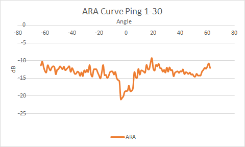
Example Plotted ARA Patch Curve from output ASCII Patch Curve file. For patch 1, pings 1 to 30.
The ASCII ARA Beam Detail option will export a test file containing the position, ping ID, beam ID, raw backscatter, corrected backscatter and incidence angle for all beams after the data have been corrected. The data do not have filtering or AVG applied and thus represent the corrected backscatter which can be useful for those who wish to use this type of data for their own seafloor characterization procedures.
The Point ARA Object option will export a point SD object that is the same as the visualization used in the previous implementation of FMGeocoder (versions 7.2.2e and earlier) as shown in the Points ARA Object figure.
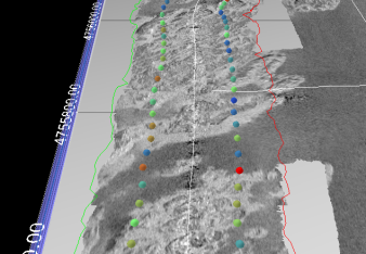
Points ARA Object
The ASCII Processed Backscatter option will export a text file containing the Backscatter and Corrected Backscatter values per ping time, ping number and beam number. In addition to these values, each entry also has associated Easting, Northing, Depth, Longitude, Latitude, True Angle, Frequency and Saturation Flag values. In order to export this file, the "Keep data for processed backscatter export" option must be checked off in the Adjust tab of your settings.
The Processed Backscatter Pixels option will export an ASCII file containing each snippet's processed intensity values with a Easting / Northing position.
The FMGT File option creates a native FMGT file that can be used as input to another project. It is the "processed" version of a source file.
