Data Object Control Region
The Data Object Control Region provides information and controls for the data objects actively loaded into Fledermaus. This section provides details that are common to all data object types. Specific information about the attribute controls of the wide variety of Fledermaus data types is found in Chapter 3 (SD Objects) of the manual. This resizable region, show in the Control Region showing the Data Set Panel figure, is located along the bottom of the Main Visualization Window. The vertical size of this region can be changed by clicking and dragging on the horizontal bar that runs along the top of this region. When the cursor is over the resize bar it changes from the standard left pointing arrow to a light crosshair cursor. Reducing the size of this region makes the Main Visualization Window larger and vice-versa.
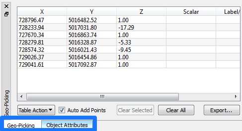
The Control Region has two different panels, the Object Attributes and the Geo-Picking panel that are activated by clicking on their respective tabs located on the bottom left. Clicking on the tab will bring that panel to the front. These panels are described below.

Object Attribute Controls
Shown to the right of the loaded object list is the attribute control area, which takes up the bulk of the display space for the Data Object Control Region. The display will change depending on the type of object currently selected in the list. These controls provide the ability to manipulate data type specific information related to the selected object. This includes things such as how the information is presented and what actions can be performed on the selected data set. Each data type in Fledermaus has its own set of controls. These can range from a few controls to a highly sophisticated system, such as the PFM sounding class, which is a substantial data processing system wrapped up into an object. The following sample screen shots illustrate attribute displays for several common object types including the SonarDTM, 3D Line, and PFM object types.
.jpg?inst-v=6b00dd1a-797f-4a2d-b385-9c7c01220309)
Sample SonarDTM class
For more information on the available tabs within the Object Attributes refer to Scientific Data (SD) Types on Data Types.
Geo-Picking
The geo-picking panel, shown in the Control Region showing the Geo-Picking display figure below, has two sets of controls on the right hand side of the display.
The first set consists of the Current Point text fields that display the actively picked point along with additional text fields that allow a coordinate to be located in the 3D visualization window. Clicking the left mouse button with the cursor in the 3D display while in Selection mode places a 3D crosshair at the picked point and fills in the X, Y, and Z coordinates in the Current Point text fields.
The second set of controls allows you to locate a coordinate location in the 3D display. After entering the X and Y coordinates in the text fields below the Locate Point button and clicking the Locate Point button, a long vertical line will be drawn through this X and Y location in the 3D scene. Clicking on the Clear Point button will clear both text fields and remove the vertical line from the 3D display.

Control Region showing the Geo-Picking display
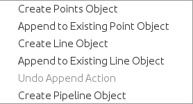
A table on the left side of the panel is used to store a number of points. When Fledermaus is in Select mode and the Auto Add Points toggle is enabled, a point will be added to the table every time a point is clicked in the Main Visualization Window with the mouse. The table lists the X, Y, Z positions for the point and a Scalar value if it exists. Any of the values in the table can be edited by double-clicking on a table cell. A label can be assigned to a point by double-clicking on a Label field and entering a value. Click the Clear All button below the table to remove all points. To import points from an XYZ file, click the Import button and select a file, or to export points from the table, click the Export button. A 3D Point object can be created from the selected points by clicking the Table Action button and selecting Create 3D Point Object. Similarly, a 3D Line object can be created by clicking the Table Action button and selecting Create 3D Line Object. It is also possible to append to an existing point or line object by selecting a valid point or line object, respectively, then clicking on Append to Existing Point Object or Append to Existing Line Object. If an unintended set of points was appended to a line object, the Undo Append Action may be used to undo the action. This facility is not available for points as of the release of 7.7.0. A Pipeline object can be created from the selected points by clicking the Table Action button and selecting Create Pipeline Object.

Table Action Listing
