
Description
Driver to decode bottom track velocity or (mean) relative water velocity from a binary output data ensemble from a Teledyne RD Instruments (RDI) Acoustic Doppler Current Profiler (ADCP) or Doppler Velocity Log (DVL).
The driver returns either:
-
The horizontal and vertical velocity along with its direction (heading) if no beam is selected, or one specific beam velocity (i.e. the velocity in relation to the sea bottom in case of a downward looking Doppler with bottom track).
-
The (mean) water velocity for all valid depth cell readings (in case of an upward looking Doppler) if a beam slot number is used.
The driver can also be used to decode the following data from the ADCP output string:
-
Depth range
-
Heading angle
-
Environmental data
When the driver is started or reset, Qinsy sends only the command "CS" to the ADCP, in order to start pinging.
The driver does not send any other commands.
(For a driver with active user interface which can send commands to the ADCP / DVL please refer to: RDI Doppler BottomTrack Speed (ASCII) (Active) - 30 - This driver decodes PD6.)
This driver can decode the binary PD0 format or the binary PD3/PD10 and PD4/PD5 formats.
The driver will automatically detect the format according to the DVL Data ID below.
|
Header ID |
Source ID |
Format |
Description |
|
0x7F |
0x7F |
PD0 |
Real water-current data set (standard WorkHorse ADCP output) |
|
0x7D |
0x00 |
PD4 |
CSS-DVL output data structure (without sensor and made-good data) |
|
0x7D |
0x01 |
PD5 |
CSS-DVL output data structure (with sensor and made-good data) |
|
0x7E |
N/A |
PD3 |
Paramax-DVL ensemble output data structure (without depth data) |
|
0x78 |
N/A |
PD10 |
Paramax-DVL ensemble output data structure (with depth data) |
-
PD0
This is RDI’s standard format. PD0 is a binary output format. It provides the most information possible including a header, fixed and variable leader, bottom track, and water profile information.
The fixed and variable leader is a recording of time, DVL setup, orientation, heading, pitch, roll, temperature, pressure, and self test diagnostic results.
Data fields to be output are user selectable:-
File Size (If BT Only) is 211 bytes binary
-
File Size (if water profile included) varies depending on the number of bins selected.
-
-
PD3
PD3 is a binary output format of bottom track speed over the bottom, speed through the water, range to bottom information, and 16 spare bytes with no definition.-
File Size is 40 bytes binary.
-
-
PD4
PD4 is a binary output format of bottom track speed over the bottom, speed through the water, and range to bottom information only.-
File Size is 28 bytes binary.
-
-
PD5
PD5 is a superset of PD4 and includes information on salinity, depth, pitch, roll, heading, and distance made good.-
File Size is 74 bytes binary.
-
-
PD6
PD6 is a text output format and not decoded by this driver.
Data is grouped into separate sentences containing system attitude data, timing and scaling, and speed through the water relative to the instrument, vehicle and earth.
Each sentence contains a unique starting delimiter and comma delimited fields.
PD6 can be decoded by two other Speed Log drivers in Qinsy: -
PD10
PD10 is similar to PD3 but with the addition of pressure and depth fields.
Driver Information
|
Driver |
OISTAR RDI Doppler BottomTrack
|
Interface Type |
Serial |
Driver Class Type |
Counted |
|---|---|---|---|---|---|
|
No |
Input / Output |
Input |
Executable |
DrvRDIDoppler.exe |
|
|
Related Systems |
|||||
|
Related Pages |
|
||||
Coding Notes
Decoding Notes
Default behaviour for the RDI driver is to:
-
Decode the horizontal bottom track velocity for a downward looking Doppler Velocity Log (DVL), when a speed observation is selected.
-
Return the (true) heading of the velocity vector, when a bearing observation is selected.
-
Decode the vertical speed
-
Perform the checksum.
Info
If the coordinate transformation system is a "BEAM" system, the driver just returns the mean value of the four beams, so this setting is not to be used.
If a specific beam has been selected in the Database Setup, the driver just returns the velocity value of this beam and the heading angle from the Variable Leader Data, otherwise the length and direction of the horizontal velocity vector are used. For a downward looking Doppler with bottom track, this is the observed velocity with respect to the sea bottom; for an upward looking Doppler, this is the mean value of all the observed velocities for all depth cells.
All velocities are relative based on a stationary instrument, so to obtain absolute velocities remove the instrument's velocity. In case of down looking Dopplers, you'll probably get relative bottom velocities too, so a 180 degree (C-O) value must be applied to the decoded angle direction.
Quality Checks
To change the default behaviour of the driver, change command line parameters in the "DRIVERS.IO" file. See paragraph below.
The driver will perform an extra quality check to determine if observations are realistic. If this check fails, the quality indicator of that observation is set to -2 and the values are not used in any computations. Limit values are given in the following table.
If the checksum is not correct, observations with a negative quality indicator (qi) are published, but not used in Qinsy. The exception are pitch & roll observations, which are not published when the qi is negative.
|
Observation |
Minimum Value |
Maximum Value |
|---|---|---|
|
Speed |
0 m/s |
100 m/s |
|
Vertical Speed |
-100 m/s |
100 m/s |
|
Angle |
0° |
359.99° |
|
Heading |
0° |
359.99° |
|
Pitch / Roll |
-20° |
20° |
|
Sound Speed |
1400 m/s |
1600 m/s |
|
Depth |
0.1 m |
999.9 m |
|
Temperature |
-5° C |
40° C |
|
Salinity |
0 ppt* |
40 ppt |
|
Pressure |
0 |
no limit |
* ppt = parts per thousand
System Interfacing
Interfacing Notes
The RS-232 cable connection must have two-way direction, both receiving (Rx) and transmitting (Tx) data, in case the Qinsy RDI driver must send a command to the unit to start pinging and will receive data ensembles.
The "DRIVERS.IO" option "PAS" can be used to suppress the sending of commands over a two-way connection.
Qinsy Config
Database Setup
Do not enter a slot number (or enter slot number 0) if the horizontal velocity is to be computed.
Enter a slot number (1 to 4) if just the velocity value for a specific beam or direction (1 to 4) is to be returned.
See the coordinate system table above for possible beam or direction slots. Makee sure to enter identical slot numbers.
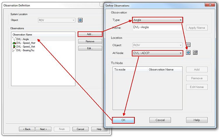
Speed Log (horizontal & vertical speed and angle)
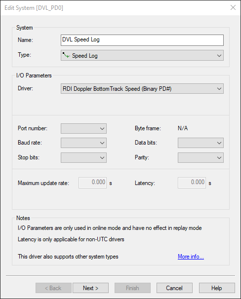
To decode horizontal & vertical speed and angle in bottom track mode, add a "System" of type "Speed Log" to the database.
Add observations of type "Angle", "Speed" and "Vertical Speed" and fill in the appropriate port settings (note that the port settings can be the same as in the RDI Doppler Speedlog system).
|
|
|
Name |
For example: "DVL" |
|---|---|
|
Type |
Speed Log |
|
Driver |
RDI Dopller Bottom Track Speed (Binary PD#) |
|
Port number |
Appropriate port settings (note that the port settings can be the same as in the RDI Doppler Speedlog system). Make sure you set the baud rate as high as possible and that the FIFO buffers of the serial port are disabled (set as low as possible). |
|
Observations Type |
"Angle", "Speed" and "Vertical Speed" |
Info
Add at least the following observations for the following objects
-
Vessel
-
Angle
-
Speed (Horizontal Speed)
-
-
ROV
-
Angle
-
Speed
-
Vertical Speed
-
Heading
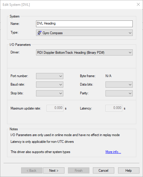
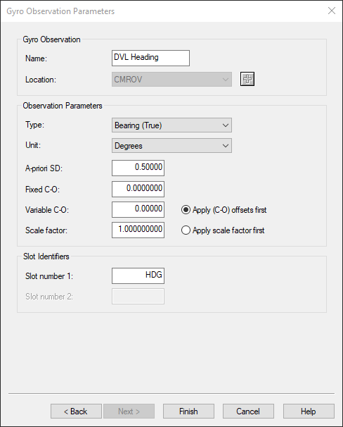
To decode the heading of the Doppler sensor, add a "System" of type "Gyro's and Compasses" to the database.
Select the driver "RDI Doppler Bottom Track (Heading)" and fill in the appropriate port settings (note that the port settings can be the same as in the RDI Doppler Speedlog system).
For the gyro observation use the slot number "HDG" for slot 1.
|
|
|
Name |
For example: "DVL Heading" |
|---|---|
|
Type |
Gyro Compass |
|
Driver |
RDI Dopller Bottom Track Heading (Binary PD#) |
|
Port number |
Appropriate port settings (note that the port settings can be the same as in the RDI Doppler Speedlog system). Make sure you set the baud rate as high as possible and that the FIFO buffers of the serial port are disabled (set as low as possible). |
|
Slot number 1 |
HDG |
Pitch Roll Heave Sensor
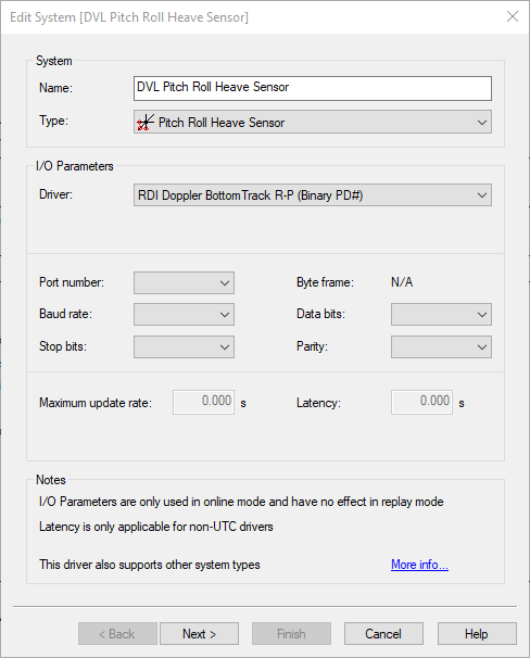
To decode roll and pitch for the doppler sensor, add a "System" of type "Pitch, Roll and Heave Sensor" to the database.
Select the driver "RDI Doppler Bottomtrack P-R" and fill in the appropriate port settings (note that the port settings can be the same as in the RDI Doppler Speedlog system).
|
|
Name |
For example: "DVL Pitch Roll Heave Sensor" |
|---|---|
|
Type |
Pitch Roll Heave Sensor |
|
Driver |
RDI Doppler Bottom Track P-R (Binary PD#) |
|
Port number |
Appropriate port settings (note that the port settings can be the same as in the RDI Doppler Speedlog system). Make sure you set the baud rate as high as possible and that the FIFO buffers of the serial port are disabled (set as low as possible). |
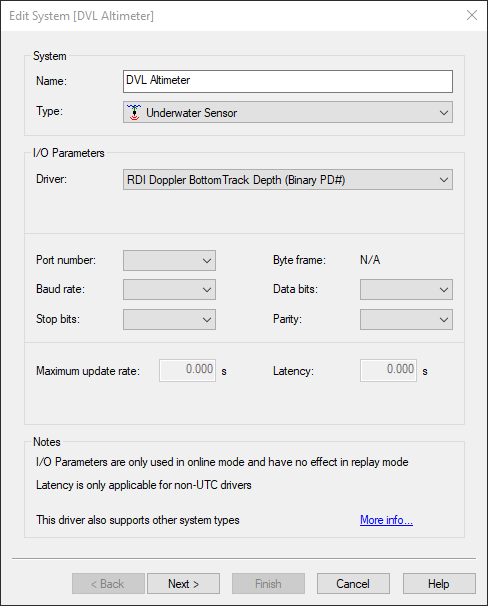
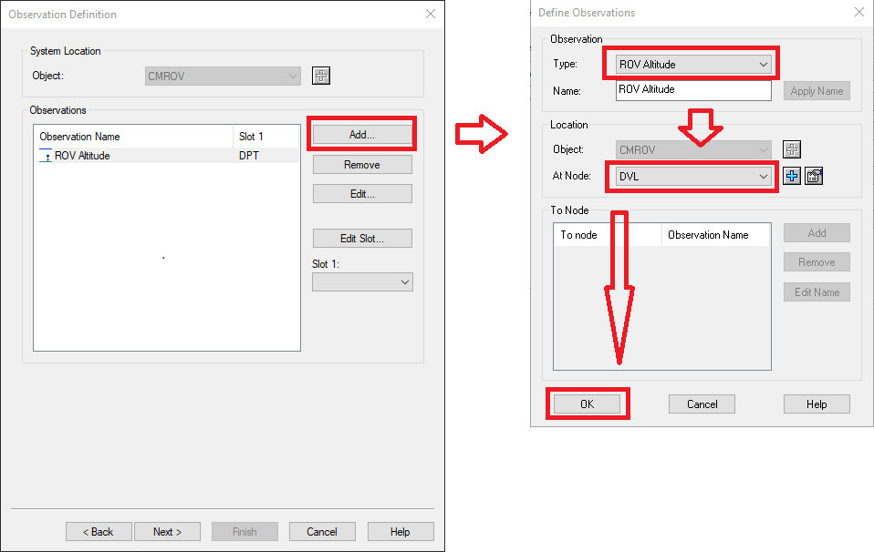
Underwater Sensor (altitude)
To decode the altitude of the ADCP from bottom track ranges, add an "Observation" of type "ROV altitude" to the database (underwater sensor) and connect this observation to the Doppler system.
For an upward looking Doppler, a zero value is returned.
For a downward looking Ddoppler, a mean or specific altitude is returned, depending on the slot as described for the speed.
|
|
|
Name |
For example: "DVL Altimeter" |
|---|---|
|
Type |
Underwater Sensor |
|
Driver |
RDI Doppler Bottom Track Depth (Binary PD#) |
|
Port number |
Appropriate port settings (note that the port settings can be the same as in the RDI Doppler Speedlog system). Make sure you set the baud rate as high as possible and that the FIFO buffers of the serial port are disabled (set as low as possible). |
|
Observation type |
ROV Altitude |
Info
For an upward looking Doppler, a zero value is returned. For a downward looking Doppler, a mean or specific altitude is returned, depending on the slot as described for the speed.
Miscellanaeous (environmental data)
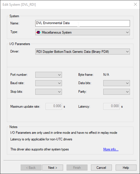
To decode the environmental data (temperature, sound velocity, depth, salinity and pressure) from the Doppler sensor, add a "System" of type "Miscellaneous" to the database.
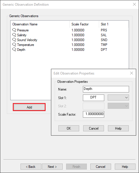
Select the driver "RDI Doppler Bottom Track (Generic)" and add the new generic observations you want to decode.
Fill in the appropriate port settings (note that the port settings can be the same as in the RDI Doppler Speedlog system).
Use the following slot IDs for the observations:
|
|
|
Name |
For example: "DVL Environmental Data" |
||||||||||||
|---|---|---|---|---|---|---|---|---|---|---|---|---|---|
|
Type |
Underwater Sensor |
||||||||||||
|
Driver |
RDI Doppler Bottom Track Depth (Binary PD#) |
||||||||||||
|
Port number |
Appropriate port settings (note that the port settings can be the same as in the RDI Doppler Speedlog system). Make sure you set the baud rate as high as possible and that the FIFO buffers of the serial port are disabled (set as low as possible). |
||||||||||||
|
Observation type |
|
Info
Recommendation by Teledyne RDI: a good check is to monitor the distance to the bottom measured by the DVL.
A rare problem can be that the DVL is bottom tracking on the secondary echo of the surface.
In Qinsy this can be accomplished by adding a System Type: "Underwater sensor" and the ROV altitude observation.
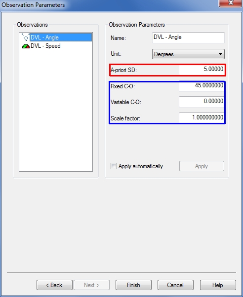
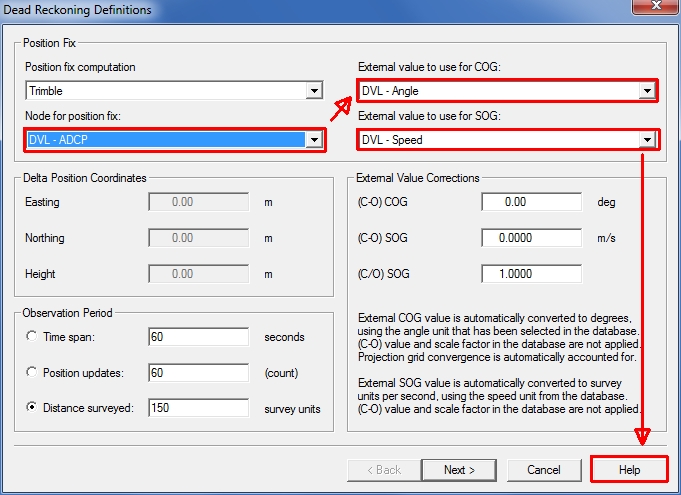
DVL/ADCP Calibration
Values found during the (Dead Reckoning) calibration procedure need to be entered on the page below in the blue section, before commencing your survey, to get the best real time results:
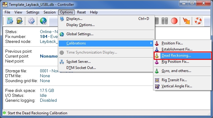
Qinsy Online
Online
Calibration
Read the Help file for further instructions!
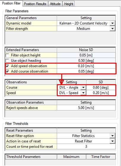
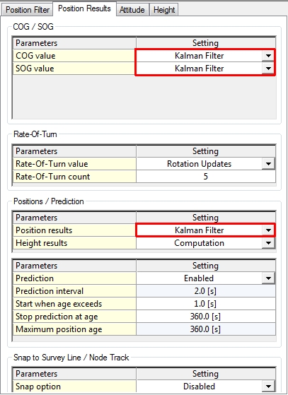
Computation Setup
The DVL is not visible in the equipment (devices) tree of the object.
The observations of the DVL can be selected via the tabs Position Filter and Position Results of the object (Vessel / ROV) it is installed on:
Smoothing Vessel or ROV Track
Please read the Knowledge Base document 'How-to Smooth Vessel or ROV Track'.
This document will give you additional information about the Computation Settings.
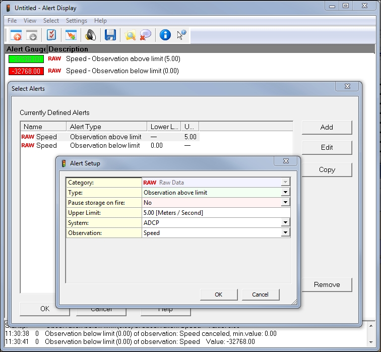
Alert Display
The Alert Display can be used to alert users on bottom track loss and exceeding the maximum speed.
When the bottom track is lost the driver will return a speed of approx -32768 m/s, and will not be used by the computation.
Additional Info
Drivers IO Notes
The Qinsy RDI driver has the possibility to validate the speed data that is being decoded. To use this feature the user has to manually edit the "DRIVERS.IO" file.
Any number that is present as command line argument will be used as the maximum speed to be accepted by the driver. Speeds exceeding the threshold will be flagged with a quality indicator of -9 and rejected in Qinsy.
Specifying the NOCS parameter will no longer reject data with an incorrect checksum. The check is still performed and the quality indicator will bet set to 999, but the data will be used anyway.
The OI parameter specifies that an OISTAR header is present before each message.
If this parameter is used, then the observation timetag will be decoded from the OISTAR header. In other cases, the timetag is defined by the moment that the DVL Data ID byte is received at the COM port.
The PAS parameter will suppress sending the start pinging command "CS" to the ADCP.