
Description
Purpose
The UKOOA format P5/94 is intended to facilitate the exchange of position data for pipelines, flowlines, umbilicals and power cables offshore (often collectively referred to as 'pipelines'). It allows the inclusion of some data in addition to pure coordinate data but is not intended to be used as an inventory of pipeline condition.
The data required for pipeline position are the Latitude and Longitude, Easting (E), Northing (N), Depth, Kilometre Point (KP), and feature where applicable, together with coordinate datum and projection parameters.
All coordinates within a file must be in a single coordinate system as given in the header records, i.e. if a pipeline crosses a grid zone boundary then a separate file for each zone is required. Similarly a separate file is required for each pipeline within a zone, i.e. if a feeder line is joined by tee-piece to a gathering line then one file is required for each pipeline.
The Qinsy P5/94 Generator driver employs an online user interface allowing recording of pipeline positioning data.
There are three variants of the P5/94 driver:
-
Standard P5/94
-
TS166 Generator
-
UPIS Generator
A format description of the standard P5/94 is available under tab "Format"
Driver Information
|
Driver |
System Cloner |
Interface Type |
|
Driver Class Type |
|
|---|---|---|---|---|---|
|
No |
Input / Output |
Input |
Executable |
DrvSystemCloner.exe |
|
|
Related Systems |
|
||||
|
Related Pages |
|
||||
Format Description
UKOOA P5/94 Format Description
Executive Summary
The P5/94 format is available to members to facilitate the exchange of pipeline, other subsea flowlines, umbilicals and power cables’ position data.
Use of this format, which is a revision of the P5/86 format is not mandatory but it is strongly recommended that it be used wherever possible.
Comments and suggestions for improvement of the format are welcome and should be addressed to:
The Chairman
Surveying and Positioning Committee
UKOOA
3 Hans Crescent
London SW I X OLN
Introduction
UKOOA format P5/94 is intended to facilitate the exchange of position data for pipelines, flowlines, umbilicals and power cables offshore. (Collectively referred to here as pipelines). It allows the inclusion of some data in addition to pure coordinate data but is not intended to be used as an inventory of pipeline condition.
The data required for pipeline position are the Latitude and Longitude, Easting (E), Northing (N), Depth, Kilometre Point (KP), and feature where applicable, together with coordinate datum and projection parameters.
All coordinates within a file must be in a single coordinate system as given in the header records, i.e. if a pipeline crosses a grid zone boundary then a separate file for each zone is required. Similarly a separate file is required for each pipeline within a zone, i.e. if a feeder line is joined by tee-piece to a gathering line then one file is required for each pipeline.
Header Record Specification
Formats of parameter data fields for each of the header record types are: -
|
TYPES |
ITEM |
COLS |
FORMAT |
|---|---|---|---|
|
H31 |
"Name of pipeline:"
|
5-21
|
A17
|
|
H32 |
"Diameter of pipeline:"
|
5-25
|
A21
|
|
H33 |
"Fluid in pipeline:"
|
5-22
|
A18
|
|
H34 |
"Pipeline operator:"
|
5-22
|
A18
|
|
H35 |
"Date of issue of tape:"
|
5-26
|
A22
|
|
H36X |
"Positioning Contractor:"
|
5-27
|
A23
|
|
H37X |
"Date of Survey:"
|
5-19
|
A15
|
|
H38X |
"Positioning system:"
|
5-23
|
A19
|
|
H39X |
"KP Range for Survey:"
|
5-22
|
A18
|
|
H40X |
"Scale of Digitisation:" Chart scale if coordinates produced by digitisation |
5-26
|
A22
|
|
H411 |
"KP Origin:"
|
5-14
|
A10
|
|
H412 |
"KP Origin Grid Coords:"
|
5-26
|
A22
|
|
H413 |
"KP Origin Lat/Long:"
|
5-23
|
A19
|
|
H42 |
"Spheroid:"
|
5-13
|
A9
|
|
H43 |
"Geodetic datum:"
|
5-19
|
A15
|
|
H44 |
"Vertical datum:"
|
5-19
|
A15
|
|
H45 |
"Projection type:"
|
5-20
|
A16
|
|
H46 |
"Projection zone:"
|
5-20
|
A16
|
|
H47 |
"Grid units: "
|
5-15
|
A11
|
|
H48 |
"Standard parallel(s):"
|
5-25
|
A21
|
|
H49 |
"Central meridian:"
|
5-21
|
A17
|
|
H501 |
"Grid Origin:"
|
5-16
|
A12
|
|
H502 |
"Coordinates at grid origin:"
|
5-31
|
A27
|
|
H511 |
" Scale factor:"
|
5-17
|
A13
|
|
H512 |
"Scale origin"
|
5-17
|
A13
|
|
H526 |
"Initial line of projection:"
|
5-31
|
A27
|
|
H527 |
"Bearing of initial line:"
|
5-28
|
A24
|
|
H528 |
"Bearing of initial line:"
|
5-28
|
A24
|
|
H529 |
"Skew angle:"
|
5-15
|
A11
|
|
H53 |
Any other relevant information |
5-80 |
A76 |
|
Notes |
Columns 1 to 4 of each Header Record are devoted to code for "type" of header e.g. H42, H501 etc. Header "types" H36X to H40X may be repeated to cater for different sections of pipeline surveyed at different times or with different positioning systems, or derived by digitisation. (X in the range 1 to 9) e.g. H361 to H401 may be first survey whilst H362 to H402 may be a second survey etc. H40X should be set to 1 if not applicable. Header record H53 may be repeated as often as necessary.
|
Data Record Specification
The general format for a data record is as follows:
|
Item |
Description |
Cols |
Format |
|---|---|---|---|
|
1 |
Record Identification for pipeline = "P" |
1 |
A1 |
|
2 |
Pipeline Identification Number e.g. PL999 |
2-17 |
A16 |
|
3 |
Kilometre Post (KP) in kilometres to nearest metre |
18-25 |
F8.3 |
|
4 |
Latitude (d.m.s N/S) |
26-35 |
I2, I2, F5.2, A1 |
|
5 |
Longitude (d.m.s E/W) |
36-46 |
I3, I2, F5.2, A1 |
|
6 |
Map Grid Easting (metres) |
47-55 |
F9.1 |
|
7 |
Map Grid Northing (metres) |
56-64 |
F9.1 |
|
8 |
Water depth in metres to local seabed level (datum defined in header) |
65-70 |
F6.1 |
|
9 |
Feature code |
71-73 |
I3 |
|
10 |
Buried (B) / Exposed (E) Indicator |
74 |
A1 |
|
11 |
Trenched (T) / Untrenched (U) Indicator |
75 |
A1 |
|
12 |
Coordinate accuracy factor (metres) |
76-79 |
I3 |
|
13 |
Blank |
80 |
|
|
Notes |
Item 3. If KP distances are not computed for a particular pipeline columns 18-25 should be left blank.
Item 12. An estimate of the absolute accuracy of the surveyed feature should be supplied since this will assist in planning future operations. Positional accuracy will obviously depend on methods employed to survey the pipeline and its features. |
Feature Code and Description
|
Feature Code |
Feature Description |
|---|---|
|
000 |
Pipeline Position |
|
001 |
Spool Piece |
|
002 |
500 m point from platform |
|
003 |
T piece |
|
310 |
Debris |
|
500 |
Anode |
|
501 |
Buckle Arrester |
|
502 |
Pipe bend |
|
503 |
Flange |
|
504 |
Valve |
|
505 |
Protective structure (igloo) |
|
506 |
Pipe clamp |
|
507 |
Mechanical Connector |
|
508 |
Other pipeline crossing over |
|
509 |
Other pipeline crossing under |
|
510 |
Grout Bag Support |
|
511 |
Grout mattress |
|
512 |
Anchor or saddle block |
|
513 |
Remote CP potential monitor |
|
514 |
Anode assembly (frame anode) |
|
700 |
Other |
|
701 |
Anchor scar |
|
800 |
Field joint |
Each feature must be assigned the most relevant code.
Return to: top of page.
Return to: P5/94 Generator Driver
Database Setup
Defining a P5/94 Generator driver is very straightforward.
Add a New System.
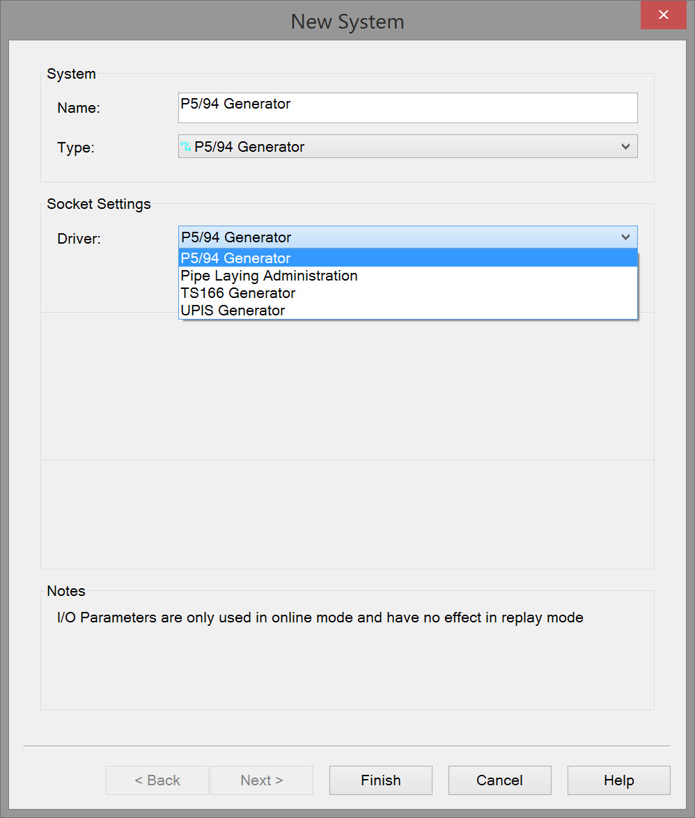
Enter a name for the driver.
Select P5/94 Generator driver from drop down list:
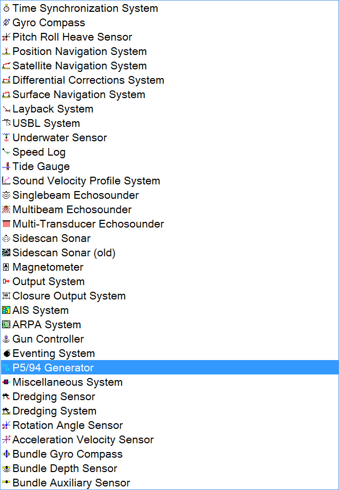
Select the P5/94 driver type:
-
Standard P5/94
-
TS166 Generator
-
UPIS Generator
Online
Standard P5/94
When starting the Online Controller, the P5/94 Generator driver with user interface is minimized in the bottom bar 
The maximized dialog box is initially empty:
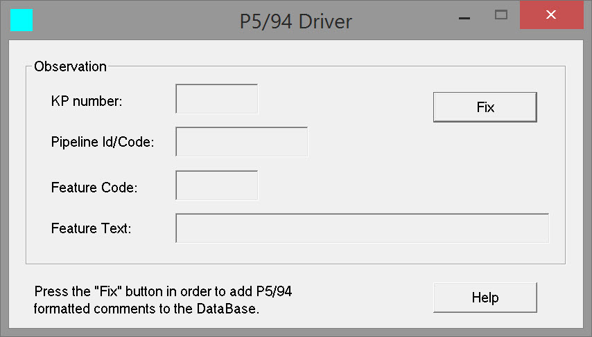
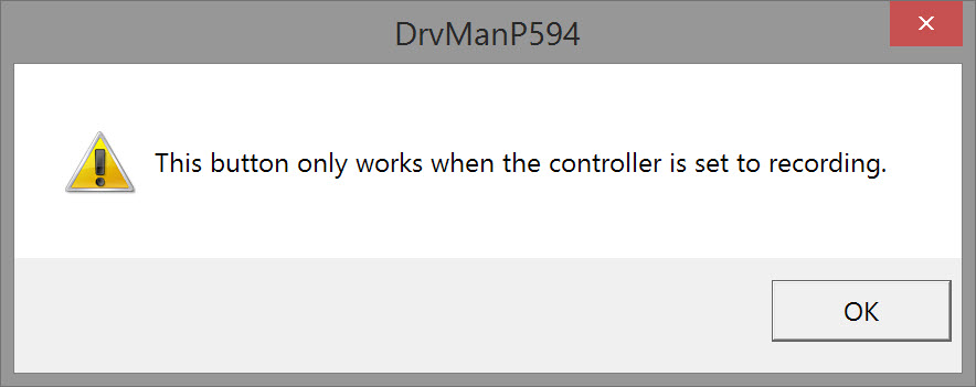
Unless in recording mode a guidance message pops up.
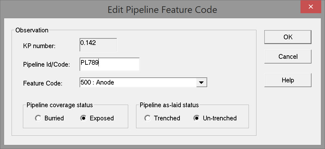
After starting recording, pressing the Fix button brings up the Edit Pipeline Feature Code window:
|
Observation |
|
|---|---|
|
KP Number |
The Kilometer Point number is reported for the instant the Fix button was pressed.
|
|
Pipeline Id/Code |
Enter a identifying string for the pipeline.
|
|
Feature Code |
Select the code from the drop down list. 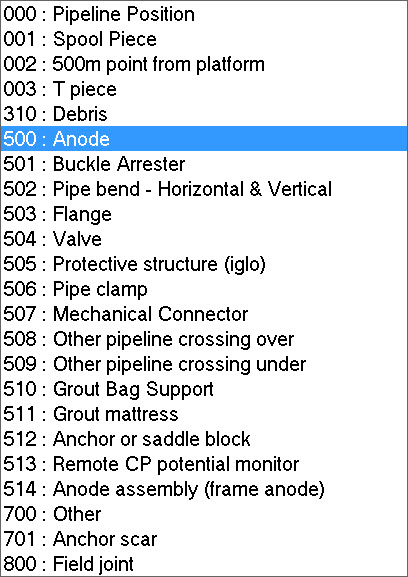
|
|
Pipeline coverage status |
Select buried or exposed. |
|
Pipeline as-laid status |
Select Trenched or Un-trenched. |
Press OK to generate the pipeline event.
Selections are reflected in the P5/94 Driver window:
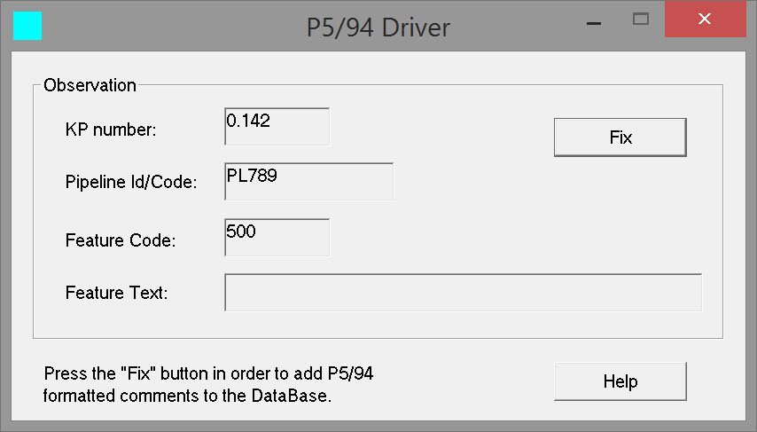
The Pipeline Id/Code and Feature Code remain selected the next time the Fix button is pressed. This can be useful if a feature like 'Field Joint' is repeated often.
TS166 Generator
When starting the Online Controller, the P5/94 Generator driver with user interface is minimized in the bottom bar
The maximized dialog box is initially empty:
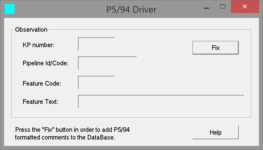
Unless in recording mode a guidance message pops up.
After starting recording, pressing the Fix button brings up the Edit TS166 Formatted Pipeline Feature Code window:
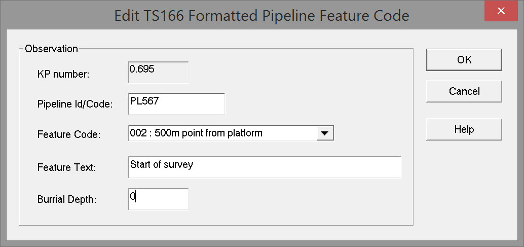
|
Observation |
|
|---|---|
|
KP Number |
The Kilometer Point number is reported for the instant the Fix button was pressed.
|
|
Pipeline Id/Code |
Enter a identifying string for the pipeline.
|
|
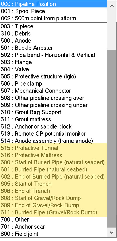
Feature Code |
Select the code from the drop down list.
|
|
Feature Text |
Enter a descriptive alphanumeric character string. This text box is activated when a fix is made. 'Feature text' can only filled in when the P5/94 generator uses the TS 166 Generator driver or the UPIS Generator. |
|
Burial Depth |
Enter a numeric value. |
Press OK to generate the pipeline event.
Selections are reflected in the P5/94 Driver window:
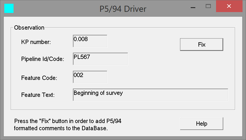
The Pipeline Id/Code and Feature Code remain selected the next time the Fix button is pressed. This can be useful if a feature like 'Field Joint' is repeated often.
UPIS Generator
When starting the Online Controller, the P5/94 Generator driver with user interface is minimized in the bottom bar
The maximized dialog box is initially empty:
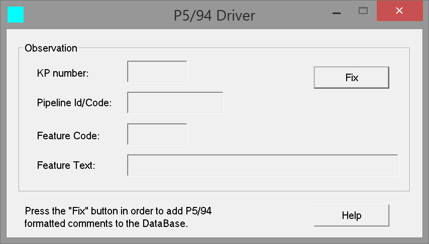
Unless in recording mode a guidance message pops up.
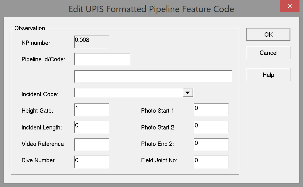
After starting recording, pressing the Fix button brings up the Edit UPIS Formatted Pipeline Feature Code window:
|
Observation |
|
|---|---|
|
KP Number |
The Kilometer Point number is reported for the instant the Fix button was pressed.
|
|
Pipeline Id/Code |
Enter a identifying string for the pipeline.
|
|
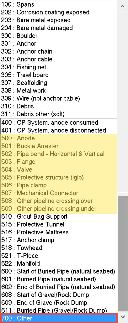
Incident Code |
Select the code from the drop down list.
|
|
Height Gate |
|
|
Incident Length |
Enter a numeric value. |
|
Video Reference |
|
|
Dive Number |
|
|
Photo Start 1 |
|
|
Photo Start 2 |
|
|
Photo End 2 |
|
|
Field Joint No. |
|
Press OK to generate the pipeline event.
Selections are reflected in the P5/94 Driver window:
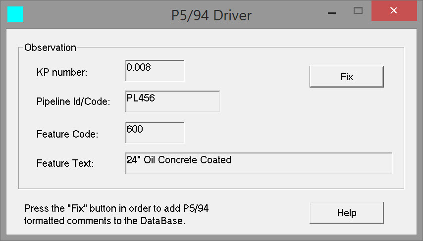
The Pipeline Id/Code and Feature Code remain selected the next time the Fix button is pressed. This can be useful if a feature like 'Field Joint' is repeated often.