
Description
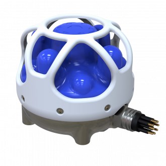
Driver to decode data from a Subsonus USBL/INS underwater acoustic positioning system using the manufacturer's own Advanced Navigation Packet Protocol (ANPP) stream.
The following data can be decoded and stored from the packet protocol stream:
-
USBL XYZ
-
USBL Targets
-
Positions
-
Heading
-
Motion (Roll and Pitch)
-
Sound velocity
-
Velocities, Accelerations and Rotations
-
Metadata (Status flags, Temperature, Pressure, etc.)
Please note that ANPP messages from the INS product line (e.g. Spatial FOG) are not 100% compatible with ANPP messages from the acoustic products, so this means that you should only use this driver for the Subsonus.
Driver Information
The Qinsy driver uses a network connection in order to communicate with the Subsonus and will act as a TCP client.
The Subsonus is by default configured as DHCP client. The downside of this is that the given IP address may change once in a while. The same IP address should be entered in the Qinsy database setup so it's very inconvenient that this changes.
Therefore you should configure the Subsonus with a static IP address in the same range as the Qinsy network interface, except for the last digit: this must be different.
For example when the Subsonus has IP address 192.168.1.10 then Qinsy should use 192.168.1.n where n is any number except 10.
The Subnet mask should be 255.255.255.0.
The Subsonus unit may have a known host-name, for example 'an-subsonus-1.local', but in the Qinsy database setup you can't use host-names.
You need to know the exact IP address instead.
For this you can use the Subsonus Tools utility in order to determine it.
Check the network connection by using the ping command from the Windows Command Prompt:
Select Start from the Windows Task bar, Run..., Cmd <Enter>, and 'ping' the address of the Subsonus unit.
For example: suppose the Subsonus IP address is 192.168.0.1.
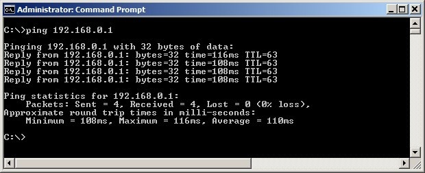
The network connection is okay when you receive a reply three times within a few milliseconds.
You could also use the Subsonus Tools utility to check for a valid network connection.
From the Advanced Navigation website you can download a useful utility called Subsonus Tools:
It is useful to perform the following three actions:
-
Determining the exact IP address of the Subsonus
-
Checking the network connection with the Subsonus
-
Logging raw data from the Subsonus for support and analyzing purposes
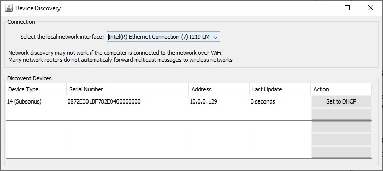
1. Determining the exact IP address of the Subsonus
Start the Subsonus Tools program and select from the File pull-down menu the option Discovery:
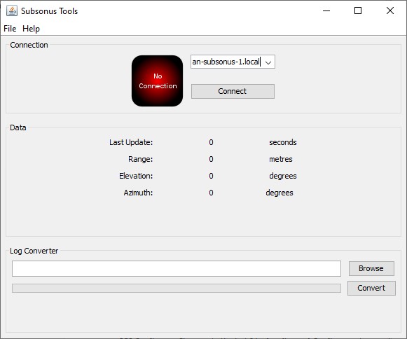
2. Checking the network connection with the Subsonus
In the main dialog of the program you can edit (or select) the host-name and then press Connect:
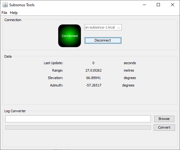
Immediately after a successful connection the program starts receiving data packets from the Subsonus.
3. Logging raw data from the Subsonus for support and analyzing purposes
After a successful connection you may press the Disconnect button:
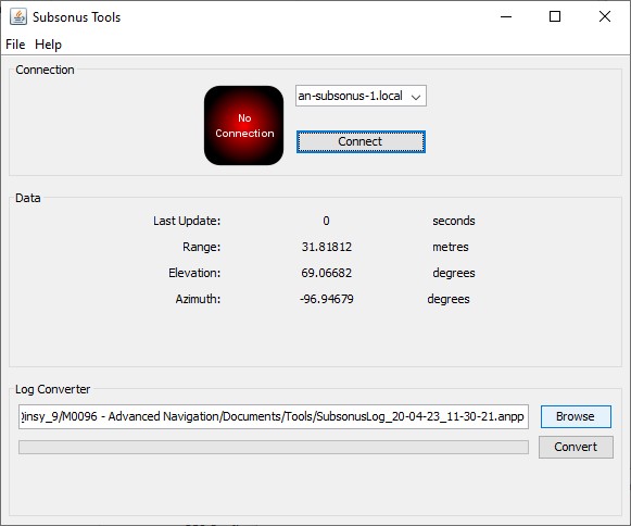
Use the Browse button to open the file location where the raw data stream has been saved as an *.anpp file.
Note that this file is still binary so you may use the Convert button to generate comma-separated ASCII files.
Subsonus surface Web GUI
When there is a successful network connection you could use a standard web browser in order to communicate directly with the Subsonus.
Enter the IP address or host-name of the unit in the address bar of the browser.
Use the View, Configuration or Tools menu to open several useful pages.
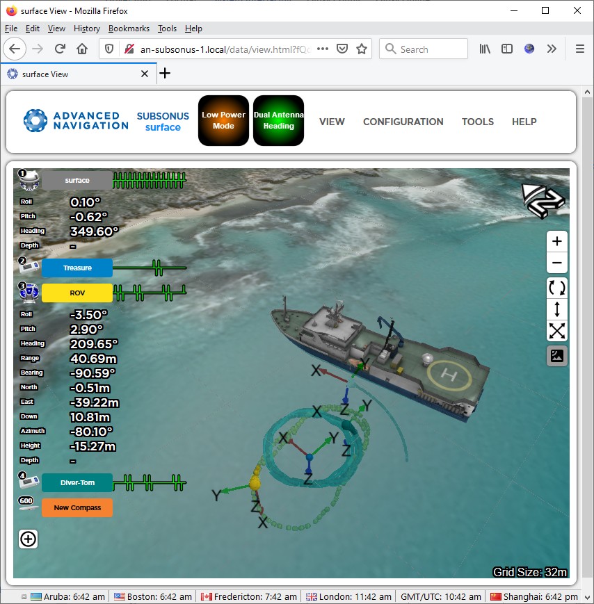
Once the configuration has been setup correctly you can use the Main page of the View menu to see if all data coming in:
Another useful page is the System Status page of the View menu:
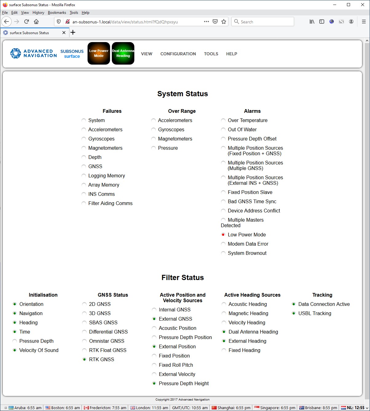
Note that the System Status and the Filter Status value is also decoded by this driver and can be monitored using a Qinsy Generic Display.
Database Setup
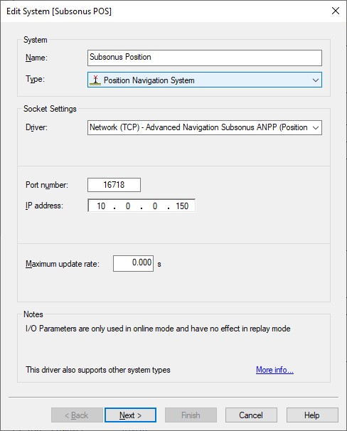
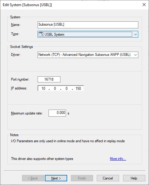
Important is to use the same interfacing settings for all 'Advanced Navigation Subsonus ANPP' systems in your template setup:
-
Port number - Just try using 16718.
Note that ANPP data packets are normally streamed over TCP via one of the following Port numbers: 16718, 16719, 16720 and/or 16721. -
IP address - Enter the IP address of the Subsonus unit.
Note that you can't enter the host-name of the Subsonus (e.g. an-subsonus-1.local). In case you need to determine the correct IP address please see section System Interfacing. -
Maximum update rate - Leave it at zero
Add one or more Position Navigation Systems to your template setup and select driver "Network (TCP) - Advanced Navigation Subsonus ANPP (Position)".
The latitude, longitude and height observations will be decoded from the System State Packet (PID 20), the Remote Track Packet (PID 24) or from the Remote State Packet (PID 25).
-
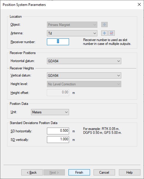
Location
Select the correct antenna location that represents the position of the Subsonus transponder, transducer or tag. -
Receiver number
Enter 0 (zero) to decode the surface or master vessel position or enter the device address of the underwater object of which you want to receive the position.
So in this example on the left the position will be the latitude, longitude and height field from the System State Packet (PID 20).
Add another Position Navigation System to your setup in case you want to decode the position from the other two packet ID's:
|
PID |
Position |
Device Address |
Receiver number |
Comment |
|---|---|---|---|---|
|
System State Packet (PID 20) |
Master |
- |
0 |
Master (surface) vessel position at high update rate |
|
Remote Track Packet (PID 24) |
Remote |
n |
n |
Underwater object position at time of acoustic measurement |
|
Remote Track Packet (PID 24) |
Local (Observer) |
n |
24nnn |
Master (surface) vessel position at time of acoustic measurement |
|
Remote State Packet (PID 25) |
Remote |
n |
25nnn |
Underwater object position at time of acoustic measurement |
-
Examples:
'0' will decode the master vessel position from packet # 20.
'4' will decode the remote position (underwater object) from packet # 24 with device address 4.
'24007' will decode the observed position (master vessel) from packet # 24 with device address 7.
'25055' will decode the remote position (underwater object) from packet # 25 with device address 55. -
Horizontal / Vertical Datum
Select the correct horizontal datum that is applicable for the latitude and longitude fields. It usually comes from an external position source but always assumed to be on WGS84.
Select the correct vertical datum that is applicable for the accompanying height field. It is also always assumed to be on WGS84.
The update rate of the System State Packet (PID 20) will be, under normal circumstances, 50 - 100 Hz. This means that the position inside this packet (master vessel) is also updated at least 50 times per second.
For accurate positioning inside Qinsy such a high update rate is not necessary and may even degrade performance, slowing down computations, increasing recorded database file sizes, etc.
By default the driver will limit the update rate of the positions inside the System State Packet to 10 Hz.
An advanced user may change this default limitation of max 10 Hz incoming positions by altering the value of the following registry key while offline:
HKEY_CURRENT_USER\Software\QPS\QINSy\8.0\Drivers\DrvQPSCountedTCP\Settings\Subsonus PID 20 MaxPosUpdateRate [Hz]
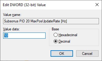
Entering a value of 0 (zero) means all incoming positions will be decoded.
The default limitation only counts for positions, all other observations (roll, pitch, heading, velocities, etc) are decoded without any restriction.
Note that the update rate of the other two packets containing also positions (Remote Track Packet (PID 24) and Remote State Packet (PID 25)) are always low under normal conditions because of the acoustic signals traveling through water and depends e.g. on the distance away of the device being tracked.
So for these packets there are also no restrictions.
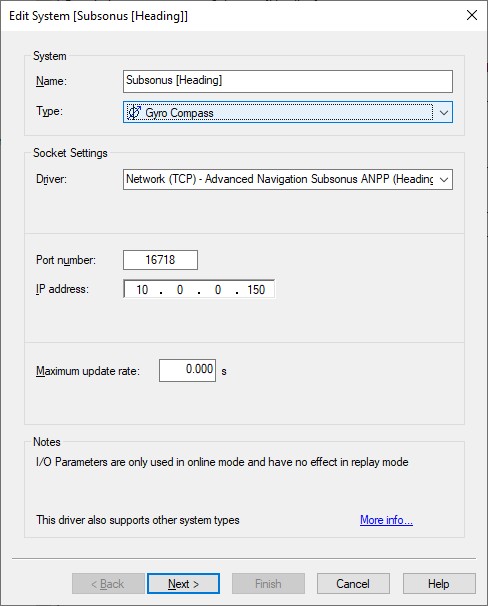
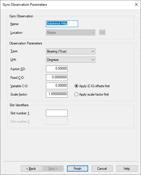
Add a Gyro Compass System to your template setup and select driver "Network (TCP) - Advanced Navigation Subsonus ANPP (Heading)".
The heading observation will be decoded from the System State Packet (PID 20) so normally this will be the heading from the master (surface) vessel.
Use the Slot Identifier if you also want to decode the heading observation from the Remote Track Packet (PID 24) or Remote State Packet (PID 25).
-
Select the correct object for the location.
Normally this will be the main survey vessel on which the Subsonus Master unit is mounted. -
Slot Identifiers
Just leave empty when you want to decode the master (surface) vessel heading.
Add another Gyro Compass system to your setup in case you want to decode the heading from the other two packet ID's:
|
PID |
Heading |
Device Address |
Slot number 1 |
Comment |
|---|---|---|---|---|
|
System State Packet (PID 20) |
Master |
- |
Master (surface) vessel heading at high update rate |
|
|
System State Packet (PID 20) |
Master |
- |
0 |
Master (surface) vessel heading at high update rate |
|
Remote Track Packet (PID 24) |
Local (Observer) |
n |
24nnn |
Master (surface) vessel heading at time of acoustic measurement |
|
Remote State Packet (PID 25) |
Remote |
n |
n |
Underwater object heading at time of acoustic measurement |
-
Examples:
Empty or '0' will decode the master vessel heading from packet # 20.
'4' will decode the remote heading (underwater object) from packet # 25 with device address 4.
'24007' will decode the master vessel heading at time of acoustic measurement from packet # 24 with device address 7.
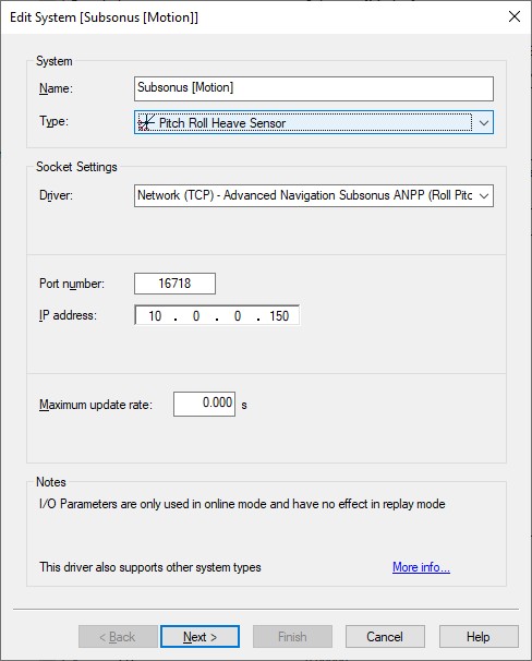
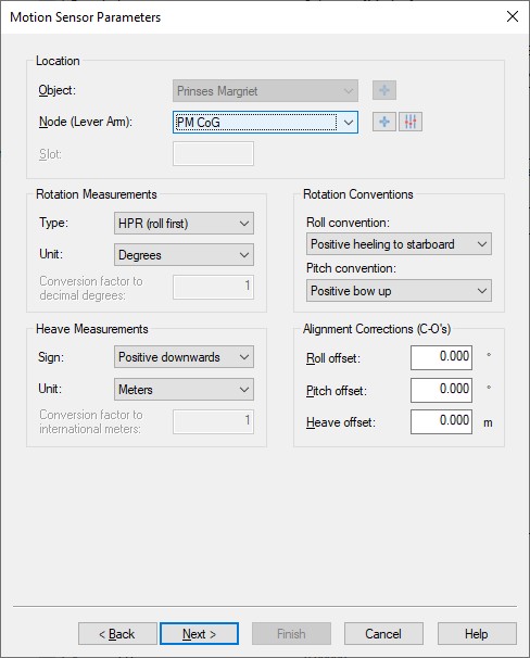
Add a Pitch Roll Heave Sensor to your template setup and select driver "Network (TCP) - Advanced Navigation Subsonus ANPP (Roll Pitch)".
The roll and pitch observation will be decoded from the System State Packet (PID 20) so normally this will be the motion from the master (surface) vessel.
-
Select the correct Node location. Normally this will be the node location of the Subsonus Master unit mounted on the main survey vessel.
-
Leave the sign conventions at their defaults: roll positive heeling to starboard, pitch positive bow up.
|
Surface vessel mounted unit |
Subsea mounted unit |
|---|---|
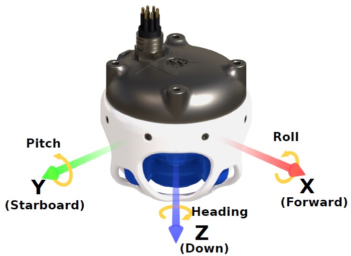 |
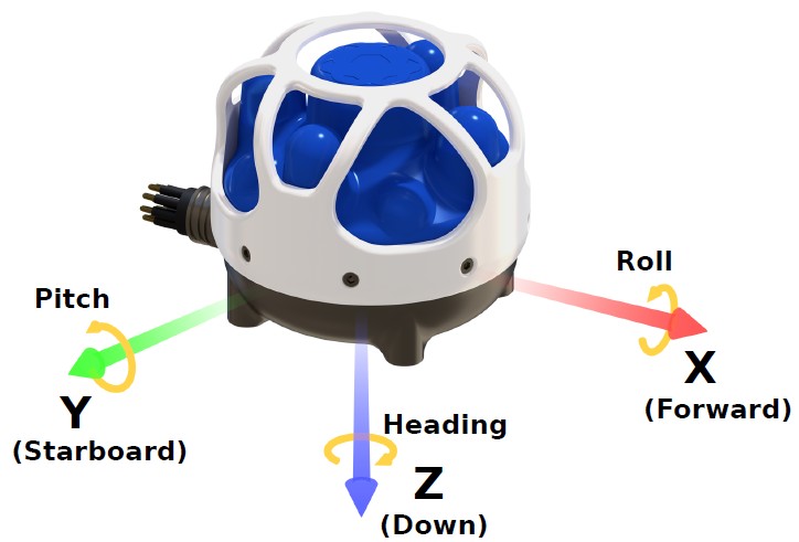 |
Illustrations from the Advanced Navigation Subsonus Reference Manual
-
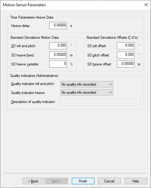
You may leave all parameters at their defaults
Add a USBL System to your template setup and select driver "Network (TCP) - Advanced Navigation Subsonus ANPP (USBL)".
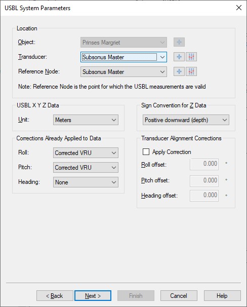
By default all USBL observations will be decoded from the roll and pitch corrected Remote Position XYZ from Remote Track Packet (PID 24).
-
Location
Select the correct Transducer location which normally will be the node location of the Subsonus Master unit mounted on the main survey vessel.
Make the Reference node the same as the Transducer. -
USBL X Y Z Data
Meters -
Corrections Already Applied to Data
If you decode the roll and pitch corrected Remote Position XYZ (default) then you should leave these settings at the default 'Corrected VRU'.
If you decode the uncorrected Remote Position Raw XYZ then you should select 'None'.
Note that whether you want to decode corrected XYZ or uncorrected raw XYZ depends on the Slot Ids which can be set on the last wizard page. -
Sign convention for Z Data
Leave it at the default setting 'Positive downward (depth)'. -
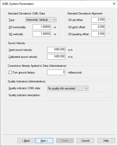
Transducer Alignment Corrections
These should be determined with a standard USBL calibration procedure: Z-Check, Spin-Test and Four-Quadrant maneuver.
Afterwards use the QPS USBL Calibration Utility to get the offset results.
It is recommended to check the checkbox and enter the found offsets here so Qinsy will correct for all the measurements.
However if desired for whatever reason it is possible to enter the offsets in the Subsonus configuration so the unit will correct the measurements before outputting them to Qinsy.
In this scenario you should leave the Apply Correction checkbox unchecked.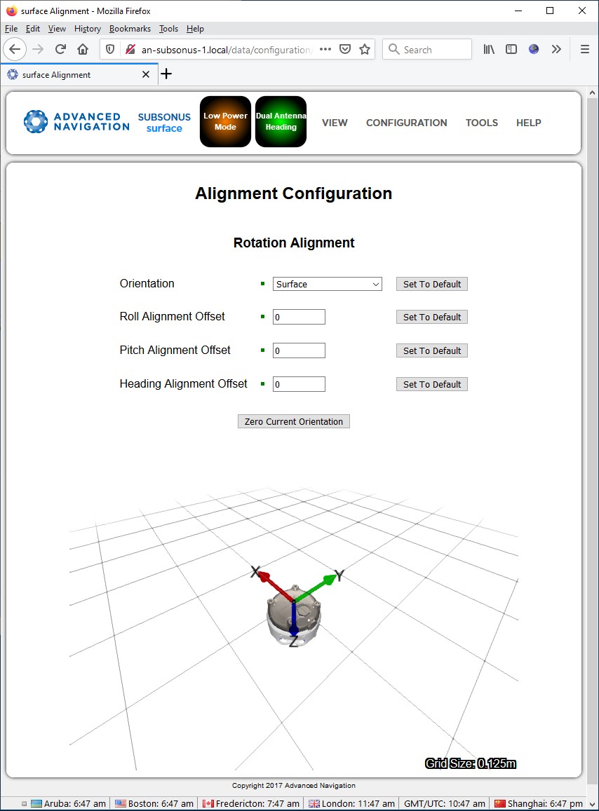
See the System Interfacing section how to access the Configuration page of the Subsonus Web GUI.
-
You may leave all parameters at their defaults
-
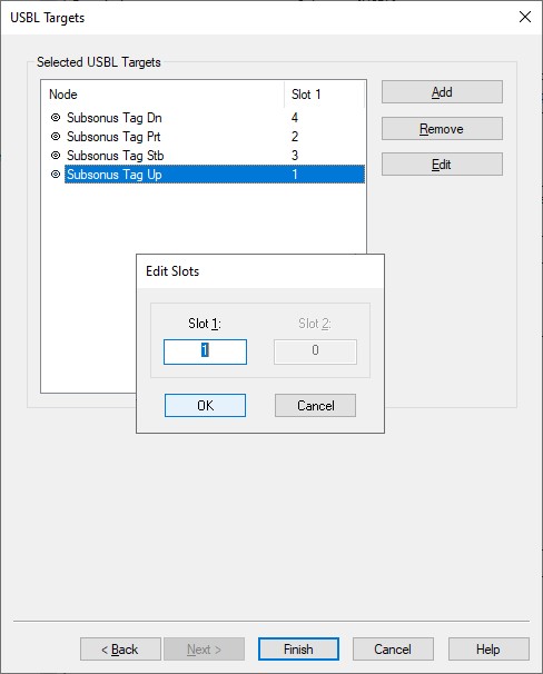
Add for each Subsonus Slave (or Transponder or Tag) a target node location.
The Slot Id must be the unique device address of the Subsonus Slave that you want to track and is a number between 1 - 255.
If you only enter a number then the roll and pitch corrected Remote Position XYZ will be used, which is recommended.
If you enter a number followed by an 'R' character then the uncorrected Remote Position Raw XYZ will be used.
If you enter a number followed by a 'C' character then also the roll and pitch corrected Remote Position XYZ is used, so this is the same as only entering a number.
Note that you can always change the Slot Id while online using the Controller's Computation Setup:
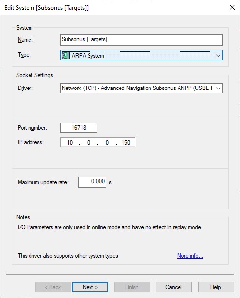
Add an ARPA System to your template setup and select driver "Network (TCP) - Advanced Navigation Subsonus ANPP (USBL Targets)".
This optional system will decode the roll and pitch corrected Remote Position XYZ from Remote Track Packet (PID 24) as ARPA target observations and therefore can be easily visualized in a Navigation Display.
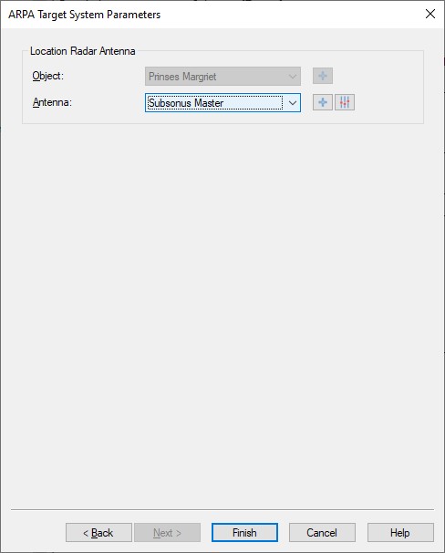
-
Select the correct Antenna location.
This node location should be the same as selected for the Transducer in the USBL System setup so normally it is the node location of the Subsonus Master unit mounted on the main survey vessel.
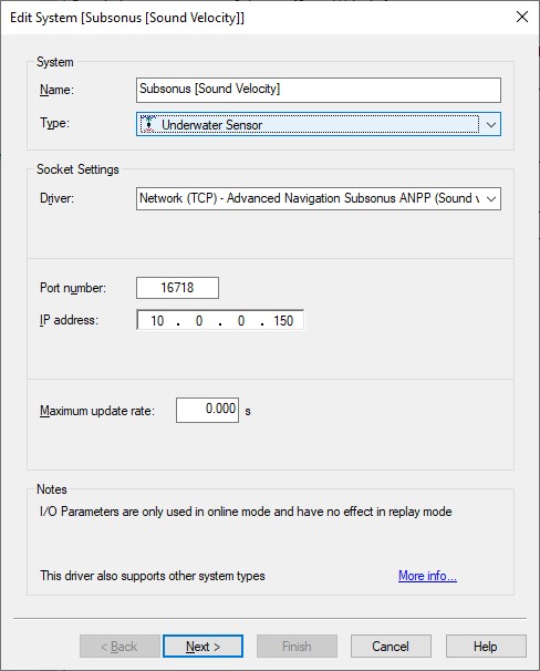
Add an Underwater Sensor to your template setup and select driver "Network (TCP) - Advanced Navigation Subsonus ANPP (Sound velocity)".
The sound velocity observation will be decoded from Raw Sensors Packet (PID 28).
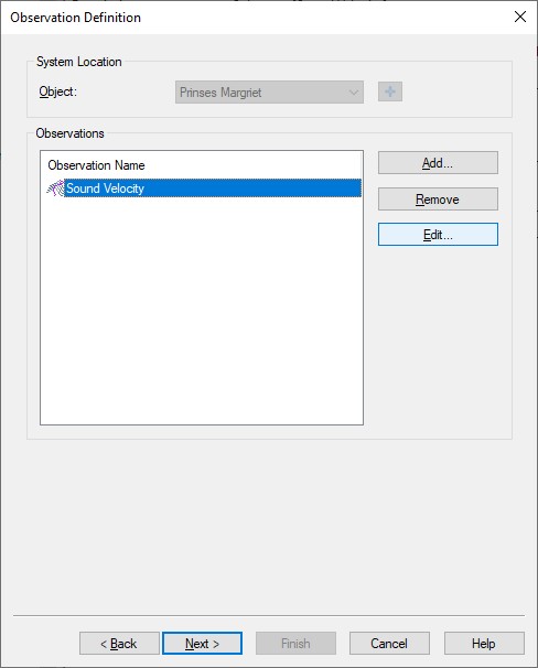
-
Add an observation of type Sound Velocity and select the location of the Subsonus Master.
You may change the default name of the observation as long as it doesn't exceed 16 characters.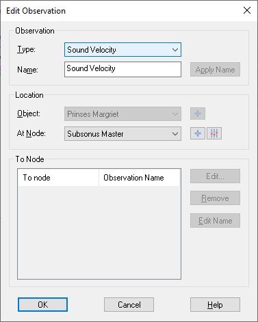
-
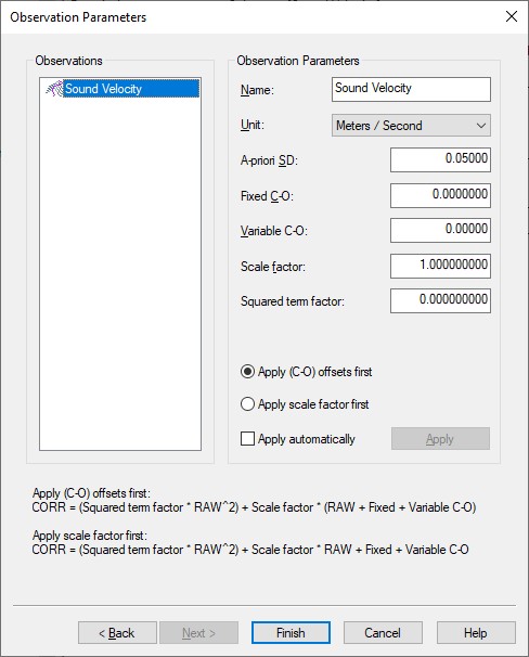
Here you can also change the default name of the observation and you may leave all parameters at their defaults.
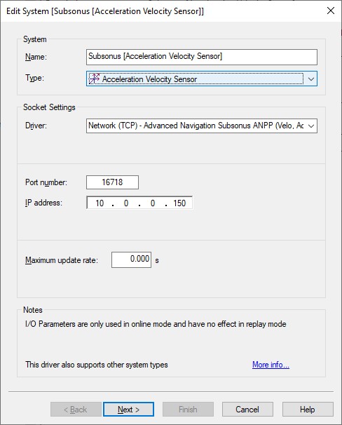
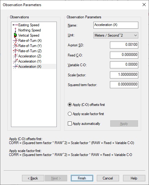
Add an Acceleration Velocity Sensor to your template setup and select driver "Network (TCP) - Advanced Navigation Subsonus ANPP (Velo, Acc, RoT)".
Velocity, acceleration and rotation observations will be decoded from the System State Packet (PID 20).
-
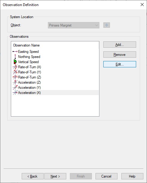
Add the required observation types that you want and select for each one the same location of the Subsonus Master.
You may change the default name for each observation as long as it doesn't exceed 16 characters.
-
Here you can also change the default name of each observation and you may leave all parameters at their defaults.
-
Speed unit must be 'Meters / Second', Acceleration unit must be 'Meters / Second^2' and Rate-of-Turn unit must be 'Degrees / Second'.
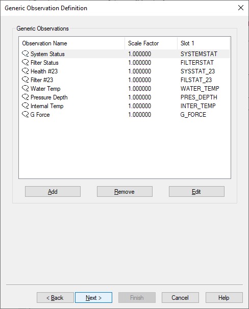
Add a Miscellaneous System to your template setup and select driver "Network (TCP) - Advanced Navigation Subsonus ANPP (Metadata)".
Generic observations will be decoded from the System State Packet (PID 20), the Status Packet (PID 23) and/or the Raw Sensors Packet (PID 28).

-
Here you can add up to eight generic observations that you may want to monitor.
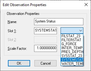
Each generic observation needs a unique Slot Id so the driver knows which field to decode.
It is highly recommended to use the drop-down selection for the correct Slot Id:
Of course you may change the default name for each observation as long as it doesn't exceed 16 characters.
|
Observation |
Packet ID |
Slot 1 |
|---|---|---|
|
System status |
System State Packet (PID 20) |
SYSTEMSTAT |
|
Filter status |
System State Packet (PID 20) |
FILTERSTAT |
|
G force (g) |
System State Packet (PID 20) |
G_FORCE |
|
Health status |
Status Packet (PID 23) |
SYSSTAT_23 |
|
System status |
Status Packet (PID 23) |
FILSTAT_23 |
|
Internal Temperature (Degrees C) |
Raw Sensors Packet (PID 28) |
INTER_TEMP |
|
Pressure Depth (m) |
Raw Sensors Packet (PID 28) |
PRES_DEPTH |
|
Water Temperature (Degrees C) |
Raw Sensors Packet (PID 28) |
WATER_TEMP |
|
Debug Information |
All packets |
DEBUG_INFO |
-
Note that the Slot ID is case-sensitive.
-
You may add manually an extra generic observation with Slot Id "DEBUG_INFO".
This special observation decodes the packet ID of each incoming packet. If that packet has a device address or device id then it will be the quality indicator of that observation.
Packets without a device address will have a quality indicator of zero.
-
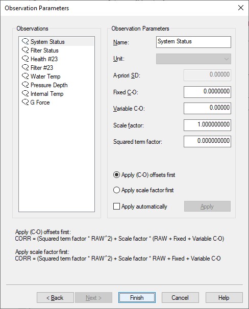
Here you can also change the default name of each observation as long as it doesn't exceed 16 characters.
You may leave all parameters at their defaults.
Online
The driver has no user-interface so you will need to set up several displays to see if data is received, decoded and what the computed results are.
You will also need to configure some important settings in the Controller's Computation Setup.
Computation Setup
The update rate for the surface (master) vessel using data from System State Packet (PID 20) is high but for the subsurface objects (using acoustic data from the Remote Packets (PID 24 & 25)) the update rate can be rather slow.
Therefore you need to make some minor adjustments to some settings of a normal computation setup, otherwise the default stale age and threshold setting will stop computing a valid position.
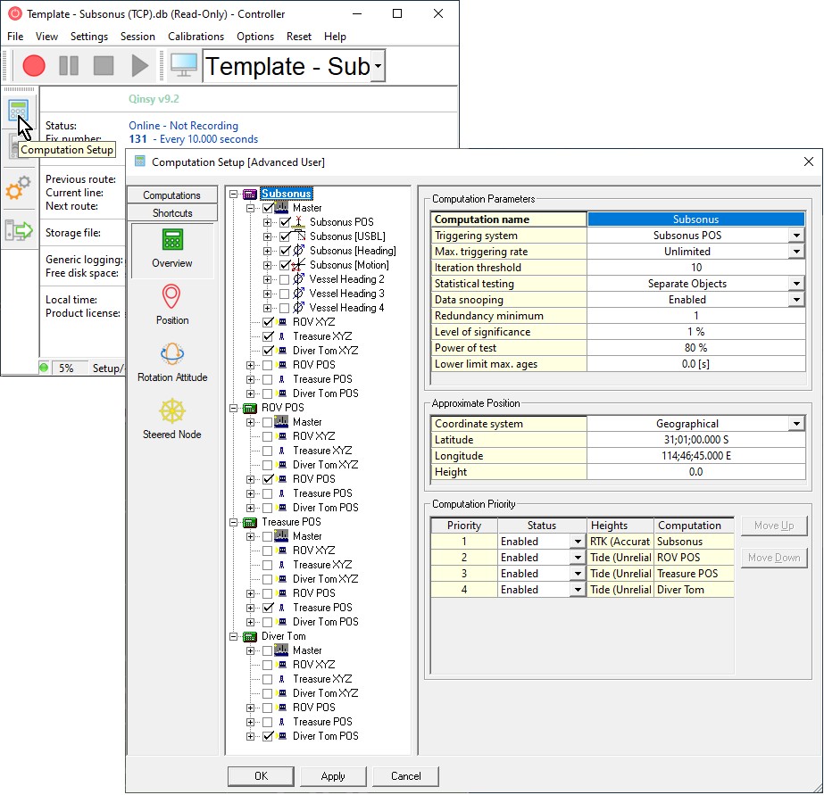
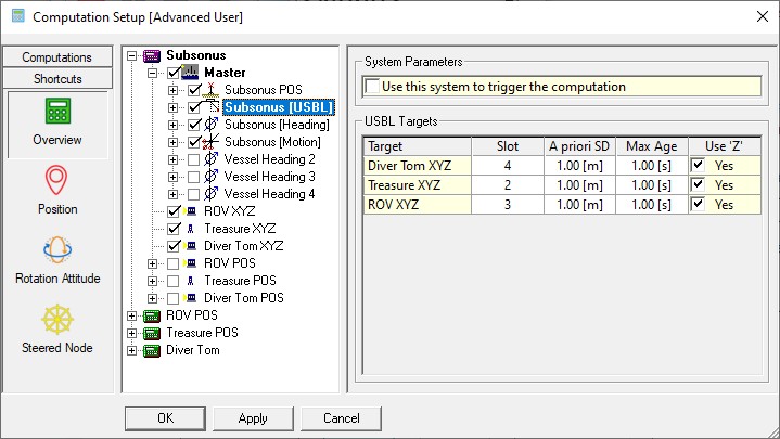
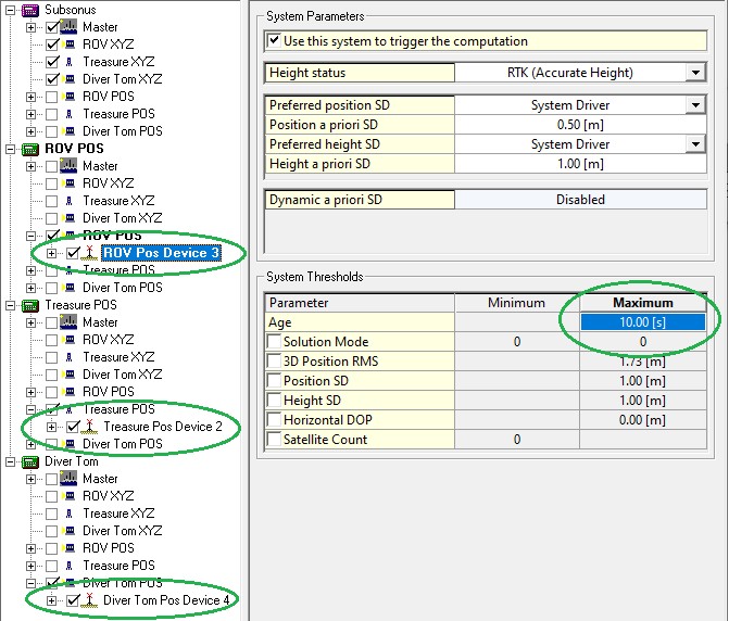
As example we use the above displayed setup containing 1 surface object (Master) and 6 underwater objects.
For this setup we define four computations:
-
1 computation (named Subsonus) computing the Master object position simultaneously with 3 underwater USBL derived positions (ROV XYZ, Treasure XYZ and Diver Tom XYZ).
-
3 separate computations: each one computing the INS derived position of each underwater objects (ROV POS, Treasure POS and Diver Tom POS).
Now change the following default settings.
-
Highlight the USBL system in the computation setup tree, go to USBL Targets and change the default Max Age of 10 sec in 1 sec.
This will force the computation to use a relative USBL measurement only once (or for very short amount of time).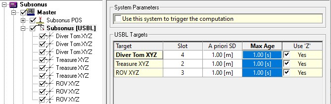
Note that this is also the page where you can change online the assigned Slot number (Device Address) without going to the offline template setup.
-
Go inside the same computation (with the USBL system enabled) to the Position Results page for each enabled underwater objects and increase the default Maximum position age of 5 sec to e.g. 10 or 15 seconds.
This ensures that you'll always have a last position update before the next update arrives.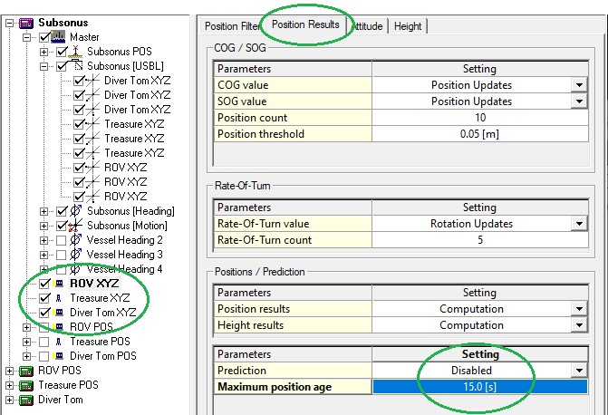
For the master object you can leave the Maximum position age to default 5 sec, because this position update should come in at a fast update rate. -
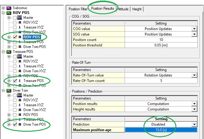
For the other three computations you should also increase the Maximum position age for the three underwater objects, because the INS derived position may also have a slow update rate.
-
Finally you should highlight each INS positioning system inside the three computations and go to the System Thresholds and increase the default Age of 5 sec to also 10 or 15 seconds.
Alert Display
Useful display to see if data is coming in at the I/O port.
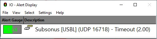
Note that although there will be multiple 'Subsonus' systems defined in your template setup you only need to add one I/O alert.
All systems use the same network IP address and port number so the displayed time-out value will be the same.
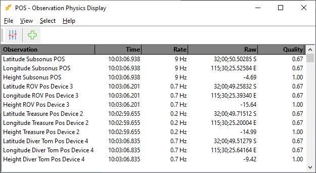
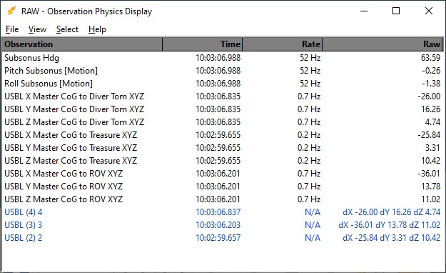
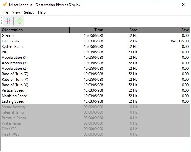
Observation Physics Display
Useful display to see if data is coming in, at what update rate and how the values are decoded.
Generic Display
A generic display is particular useful to show the meaning of the individual bits of the system status and filter status flag value.
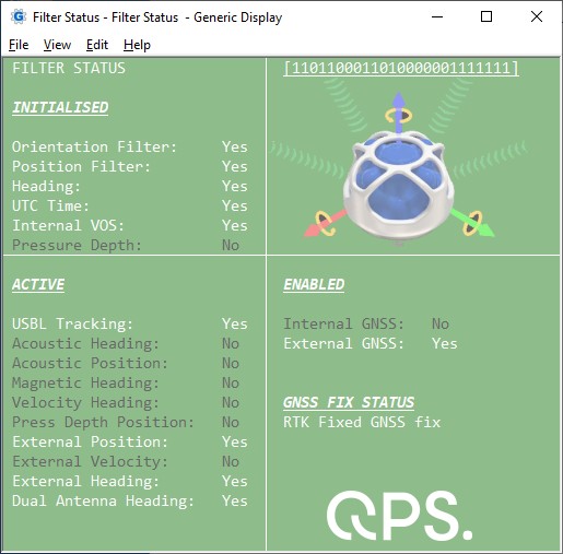
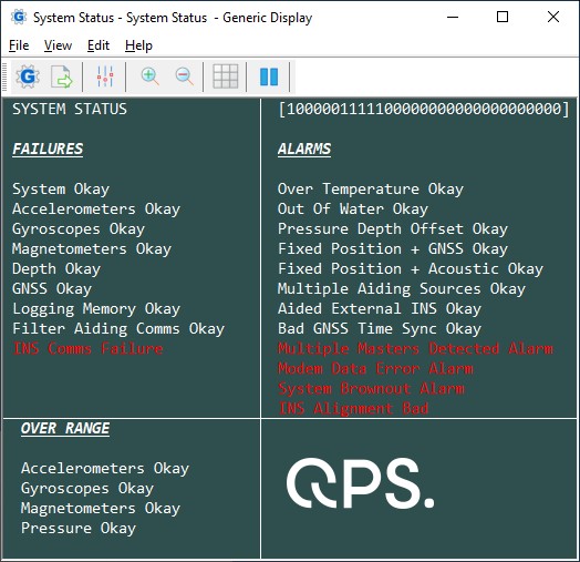
You may use the attached Filter Status.xml and/or System Status.xml file as example for getting all the information from the two Status values from System State Packet (PID 20) .
Copy the layout (Use right-mouse 'Save Link As...') to your current Project's Settings\Display folder and open it using a new Generic Display.
Please note that Save as will not work when you are viewing this document offline through the Qinsy Console; it is only accessible via the QPS website.
After downloading you only need to select the correct miscellaneous system and generic observation as defined in your template setup and the correct positioning system:
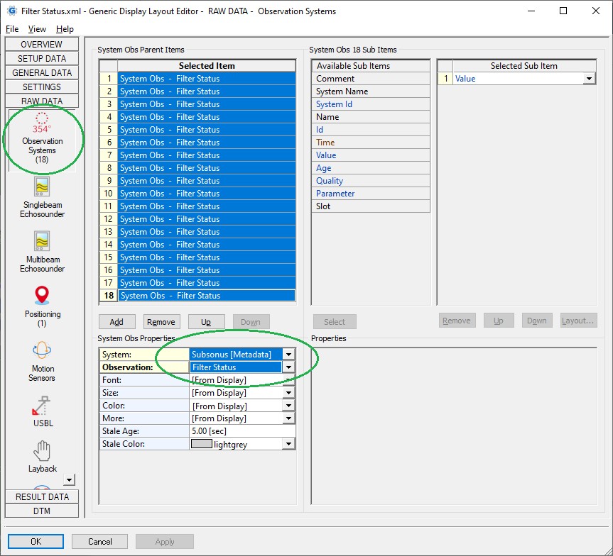
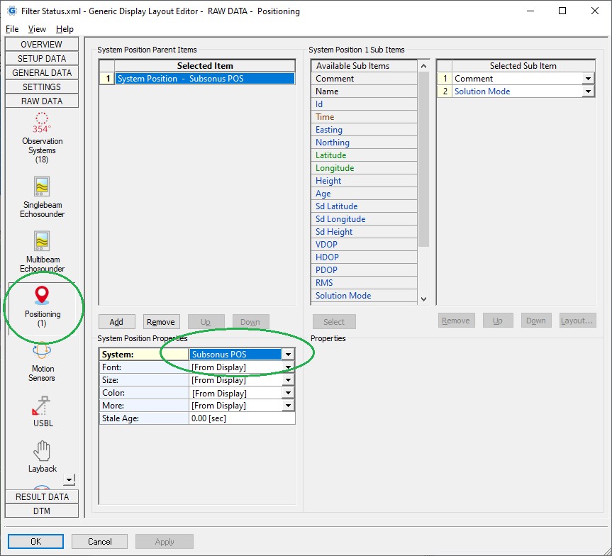
(the pictures in this example are also not embedded but feel free to browse for your own ones)
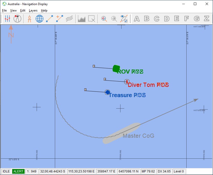
Navigation Display
Use a Navigation Display to visualize all objects and compare the subsurface ones positioned by the different methods:
-
enable and show objects which are positioned by the relative USBL measurements (from the Remote Track Packet (PID 24))
-
enable the targets representing the USBL derived positions (the roll and pitch corrected Remote Position XYZ from Remote Track Packet (PID 24))
-
enable and show objects which are positioned by the INS derived solution (from System State Packet (PID 20), Remote Track Packet (PID 24) or Remote State Packet (PID 25))
If Qinsy has been setup correctly and all is working okay then the same objects should be on top of each other.
Note that in order to visualize the detected device ids decoded as ARPA targets you'll need to enable the 'Other system targets' setting which can be found under View Properties, Layers, Targets:
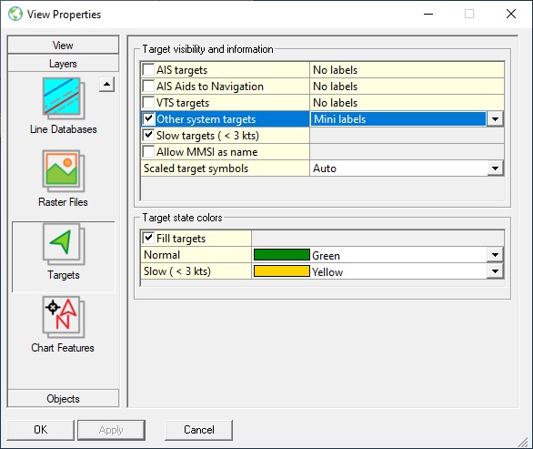
Make sure to select 'Mini labels' so the device id address will be displayed and it is recommended to enable setting 'Slow targets (< 3 kts)'.