
Description
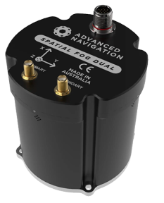
Driver to decode data from a Spatial FOG Dual inertial navigation system (INS) using the manufacturer's own Advanced Navigation Packet Protocol (ANPP) stream.
Other products from the Inertial Systems product line are also supported but not all of them have been field tested.
The following data can be decoded and stored from the packet protocol stream:
-
Position
-
Heading
-
Motion (Roll, Pitch and Heave)
-
Velocities, Accelerations and Rotations
-
Metadata (Status flags, Temperature, Pressure, etc.)
Please note that ANPP messages from the acoustic product line (e.g. Subsonus) are not 100% compatible with ANPP messages from the INS products so this means that you should only use this driver for the Spatial FOG INS.
Driver Information
When using the serial driver make sure to use the RS-232 interface because Qinsy doesn't support (in general) RS-422.
Note that Qinsy v9.5.1 (and newer versions) will also support a network interfacing (TCP) with the Spatial FOG sensor.
The UDP network interface is not supported by this driver.
The driver will use the time from the System State Packet (PID 20) message for time-stamping.
But only when the Filter Status 'UTC Time' has been initialized.
In order to check this you may use:
-
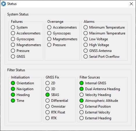
the Status dialog of the Spatial FOG Manager: the bullet point Time must be green.
-
Use a Generic Display to monitor the Filter Status value: Bit 3 must be set.
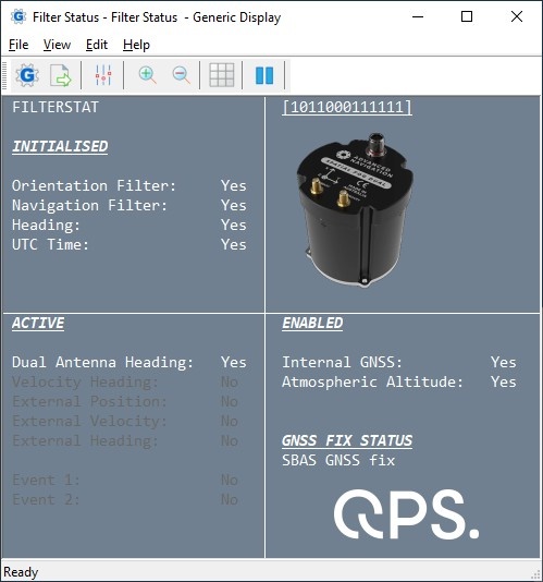
See paragraph Qinsy Online, Displays, Generic Display for more information about the Filter Status values.
When the Filter Status UTC Time is not (yet) initialized then the driver will time-stamp the data upon arrival.
You may test the incoming data using the manufacturer's own software called Spatial FOG Manager which can be downloaded from their website.
Note that this software requires for Java to be installed on your computer.
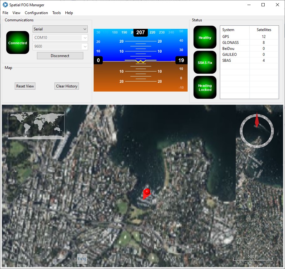
Because of the serial connection you can't connect simultaneously, so before going online with Qinsy you should disconnect the Spatial FOG Manager from the sensor.
(Of course use in the Qinsy template setup the same COMport and baudrate.)
From the View pull-down menu you can select all kinds of dialogs showing specific sensor information.
A useful display to select from the Spatial FOG Manager View menu is the Status dialog:
Note that most of this sensor specific information can also be monitored using the Qinsy displays while working online and this will also be recorded for processing and analyzing.
Database Setup
It is important to use the same interfacing settings for all 'Advanced Navigation Spatial ANPP' systems in your template setup.
Add a Position Navigation System to your template setup and select driver "Advanced Navigation Spatial ANPP (Position)" when using the serial I/O interface or "Network (TCP) - Advanced Navigation Spatial ANPP (Position)" when using the network interface.
The latitude, longitude and height observation and their standard deviations will be decoded from the System State Packet (PID 20).
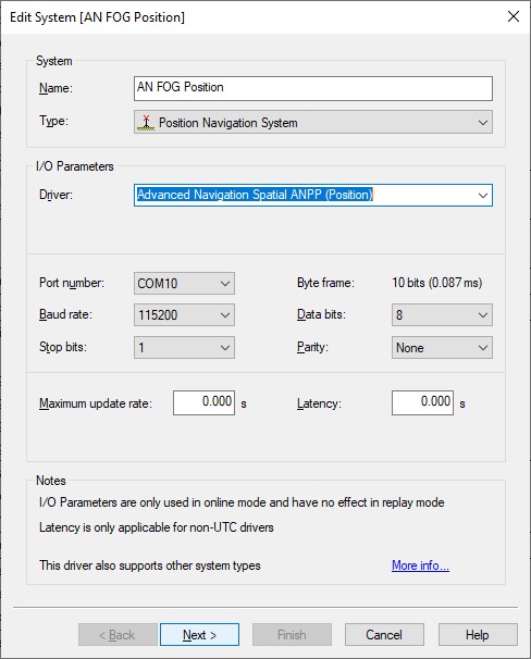
Serial interface
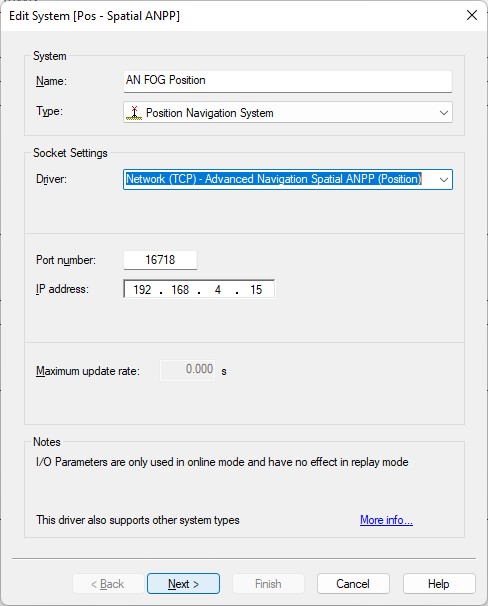
Network interface
-
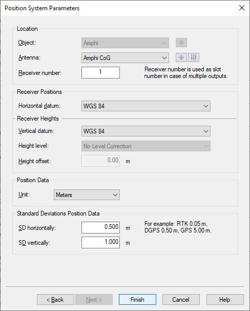
Location
Select the correct antenna location that represents the position of the INS sensor. -
Receiver number
Not used by this driver as Slot ID (only one position will be decoded from all the incoming messages) -
Horizontal / Vertical Datum
Select the correct horizontal datum that is applicable for the latitude and longitude fields.
Select the correct vertical datum that is applicable for the accompanying height field.
Both datums are always assumed to be on WGS84.
The update rate of the System State Packet (PID 20) will be (under normal circumstances) 20 Hz or higher.
For accurate positioning inside Qinsy such a high update rate is not necessary and may even degrade performance, slowing down computations, increasing recorded database file sizes, etc.
By default the driver will limit the update rate of the positions inside the System State Packet to 10 Hz.
An advanced user may change this default limitation of max 10 Hz incoming positions by altering the value of the following registry key while offline:
Serial driver: HKEY_CURRENT_USER\Software\QPS\QINSy\8.0\Drivers\DrvQPSCounted\Settings\Spatial PID 20 MaxPosUpdateRate [Hz]
Network driver: HKEY_CURRENT_USER\Software\QPS\QINSy\8.0\Drivers\DrvQPSCountedTCP\Settings\Spatial PID 20 MaxPosUpdateRate [Hz]
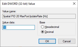
Entering a value of 0 (zero) means all incoming positions will be decoded.
The default limitation only counts for positions, all other observations (roll, pitch, heading, velocities, etc) are decoded without any restrictions.
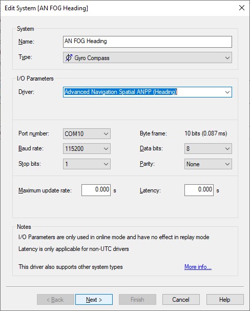
Add a Gyro Compass System to your template setup and select driver "Advanced Navigation Spatial ANPP (Heading)" when using the serial I/O interface or "Network (TCP) - Advanced Navigation Spatial ANPP (Heading)" when using the network interface.
The heading observation will be decoded from the System State Packet (PID 20) and its quality indicator will be standard deviation as decoded from the Euler Orientation Standard Deviation Packet (PID 28).

-
Unit must be 'Degrees'.
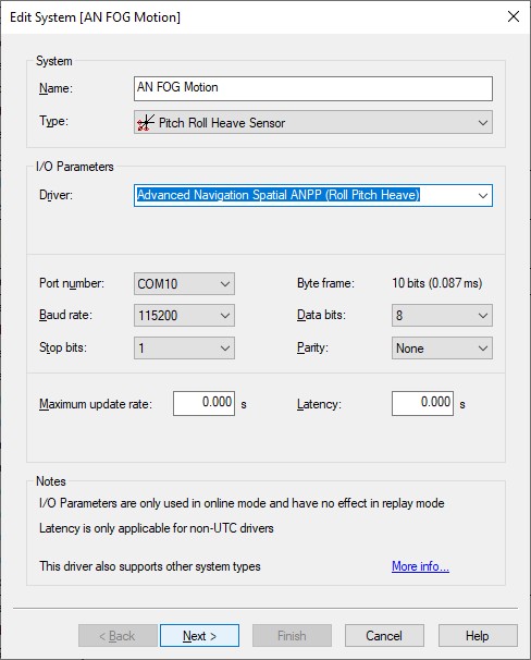
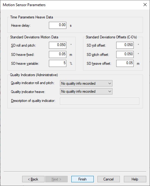
Add a Pitch Roll Heave Sensor to your template setup and select driver "Advanced Navigation Spatial ANPP (Roll Pitch Heave)" when using the serial I/O interface or "Network (TCP) - Advanced Navigation Spatial ANPP (Roll Pitch Heave)" when using the network interface.
The roll and pitch observation will be decoded from the System State Packet (PID 20).
The heave will be decoded from the Heave Packet (PID 58) heave point 1 field.
Therefore it is important to set the Primary Reference Point offsets (Heave Point 1) to zero in the setup of the Spatial FOG Manager.
For this system to work correctly it is mandatory that Heave Packet (PID 58) is enabled, next to System State Packet (PID 20).
-
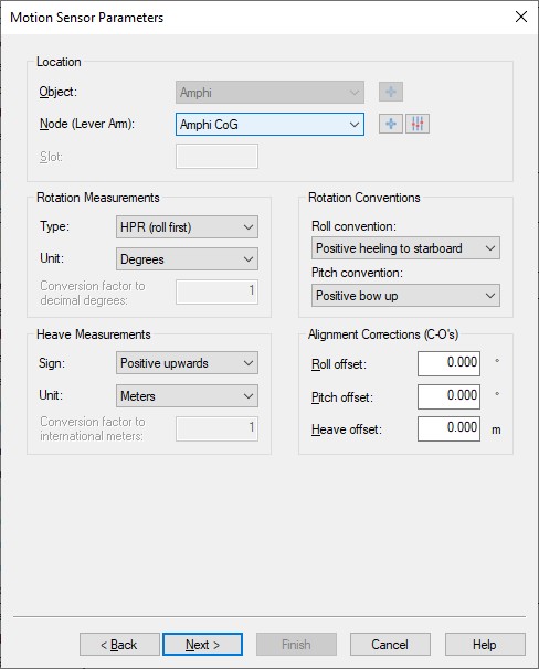
Select the correct Node location.
This will be the node location of where the Spatial FOG INS is mounted on the vessel. -
Make sure to use to following sign conventions:
-
Roll: Positive heeling to starboard
-
Pitch: Positive bow up
-
Heave: Positive upwards
-
Rotation Measurement Type: HPR (roll first)
-
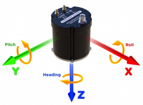
Illustrations from the Advanced Navigation Spatial FOG Reference Manual
-
You may leave all parameters at their defaults
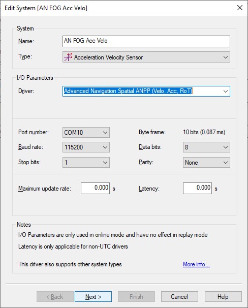
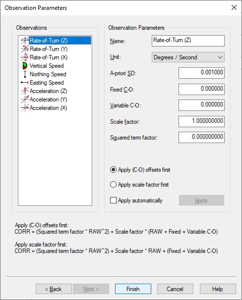
Add an Acceleration Velocity Sensor to your template setup and select driver "Advanced Navigation Spatial ANPP (Velo, Acc, RoT)" when using the serial I/O interface or "Network (TCP) - Advanced Navigation Spatial ANPP (Velo, Acc, RoT)" when using the network interface.
Velocity, acceleration and rotation observations will be decoded from the System State Packet (PID 20).
-
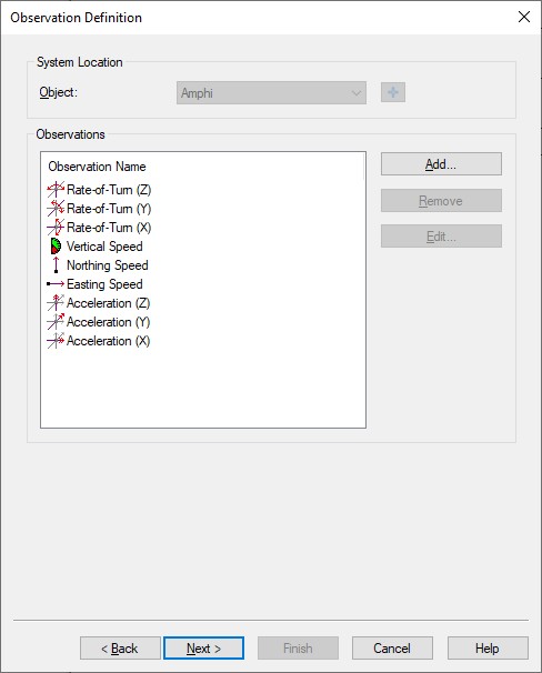
Add the required observation types that you want and select for each one the same location of the Spatial FOG INS.
You may change the default name for each observation as long as it doesn't exceed 16 characters.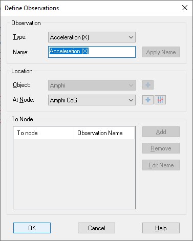
-
Here you can also change the default name of each observation and you may leave all parameters at their defaults.
-
Speed unit must be 'Meters / Second', Acceleration unit must be 'Meters / Second^2' and Rate-of-Turn unit must be 'Degrees / Second'.
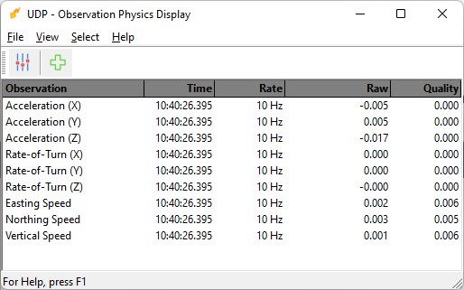
Adding velocity, acceleration and rotation observations can be useful for analyzing purposes e.g. by monitoring their values in real-time using an Observation Physics Display or graphically using a Timeplot Display.
However these type of observations will not be used by Qinsy to enhance the computation results.
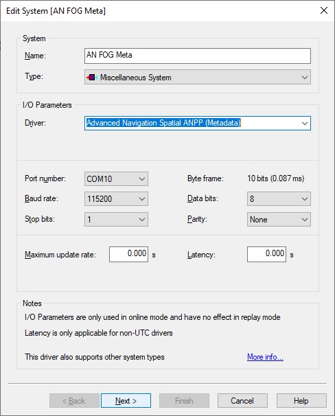
Add a Miscellaneous System to your template setup and select driver "Advanced Navigation Spatial ANPP (Metadata)" when using the serial I/O interface or "Network (TCP) - Advanced Navigation Spatial ANPP (Metadata)" when using the network interface.
Generic observations will be decoded from the System State Packet (PID 20) and the Raw Sensors Packet (PID 28).
-
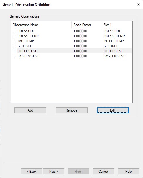
Here you can add up to six generic observations that you may want to monitor.
Each generic observation needs a unique Slot Id so the driver knows which field to decode.
It is highly recommended to use the drop-down selection for the correct Slot Id: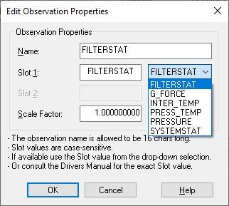
Of course you may change the default name for each observation as long as it doesn't exceed 16 characters.
|
Observation |
Packet ID |
Slot 1 |
|---|---|---|
|
System status |
System State Packet (PID 20) |
SYSTEMSTAT |
|
Filter status |
System State Packet (PID 20) |
FILTERSTAT |
|
G force (g) |
System State Packet (PID 20) |
G_FORCE |
|
IMU Temperature (Degrees C) |
Raw Sensors Packet (PID 28) |
INTER_TEMP |
|
Pressure (Pascals) |
Raw Sensors Packet (PID 28) |
PRESSURE |
|
Pressure Temperature (Degrees C) |
Raw Sensors Packet (PID 28) |
PRESS_TEMP |
|
Debug Information |
All packets |
DEBUG_INFO |
-
Note that the Slot ID is case-sensitive.
-
You may add manually an extra generic observation with Slot Id "DEBUG_INFO".
This special observation (useful for debugging or analyzing purposes) will decode the packet ID of each incoming packet even if the contents of that packet are not decoded by the driver.
Further, if that packet has a device address or device id, then it will be the quality indicator of that observation.
Packets without a device address will have a quality indicator of zero.
-
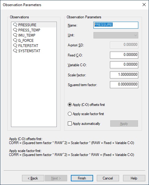
Here you can also change the default name of each observation as long as it doesn't exceed 16 characters.
You may leave all parameters at their defaults.
In this example observation PRESSURE has been selected. Note that the value will be decoded from the Raw Sensor Packet (PID 28) and has unit Pascal.
If you set the Scale factor in this dialog to 0.00001 you will get for the corrected value in Qinsy the pressure value in unit Bars.
Online
The driver has no user-interface so you need to set up several displays to see if data is received, decoded and what the computed results are.
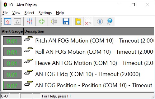
Alert Display
Always useful as a starter to see if data is coming in at the I/O port.
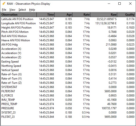
Observation Physics Display
Useful display to see if data is coming in, at what update rate and how the values are decoded.
Generic Display
A generic display is particular useful to show the meaning of the individual bits of the SYSTEM STATUS and FILTER STATUS flag value.
So with this display you can easily monitor the same important information as you would see using the Spatial FOG Manager's Status View (as described in the System Interfacing paragraph of this document).
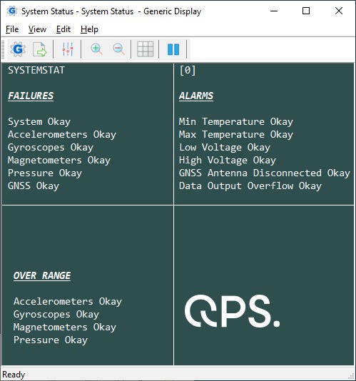

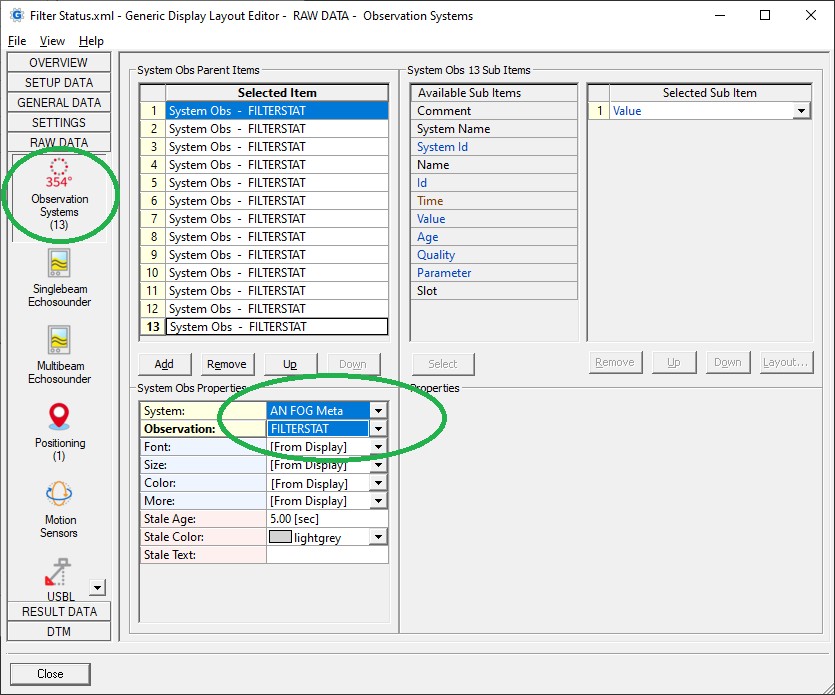
You may use the attached System Status.xml and/or Filter Status.xml file as example for getting all the information from the two Status values from System State Packet (PID 20) .
Copy the layout (Use right-mouse 'Save Link As...') to your current Project's Settings\Display folder and open it using a new Generic Display.
Please note that Save as will not work when you are viewing this document offline through the Qinsy Console; it is only accessible via the QPS website.
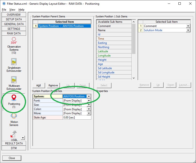
After downloading you only need to select the correct miscellaneous system and generic observation as defined in your template setup and the correct positioning system:
The pictures in this example are also not embedded but feel free to browse for your own ones 😉