Description
This is a driver to exchange information with the IHC DigiSys system.
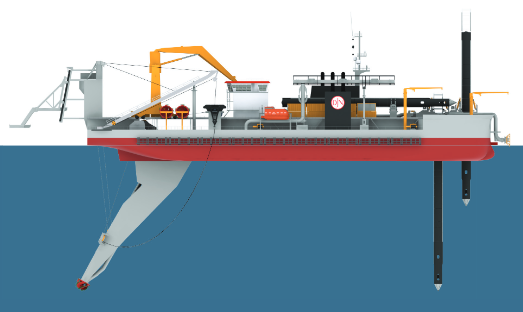
The main function of the IHC DigiSys system is to present dredging information on board a cutter suction dredger.
It is capable of sending and receiving ASCII-based messages.
The message that is sent by the driver contains the following types of information:
-
Tide information: used tide value and status
-
3D position of the pontoon in projection grid coordinates including position & height status
-
Work spud chainage and offset to the active center line
-
Projection grid convergence
-
Some spare fields
The message that is received by the driver contains the following types of information:
-
Draft of the pontoon
-
Spud carrier position
-
Pitch & roll of the pontoon
-
Tide information: used tide value and status
-
Heading of the pontoon
-
Density & velocity of mixture
-
Cutter head identifier
-
Ladder angle
-
Roll & pitch of the the work spud
-
Relative & Absolute position of center of cutter
-
Relative & Absolute position of cut point
-
Relative & Absolute position of calibration point
-
Relative & Absolute position of work spud tip
-
Relative & Absolute position of auxiliary spud tip
-
Absolute position of starboard anchor
-
Absolute position of port anchor
-
10 user configurable observations
Driver Information
|
Driver |
Network - IHC Dredging (ASCII) |
Interface Type |
Network UDP |
Driver Class Type |
Terminated |
|---|---|---|---|---|---|
|
No |
Input / Output |
Input and Output |
Executable |
DrvOutIhcUdp.exe DIGISYS_ASCII |
|
|
Related Systems |
|
||||
|
Related Pages |
|
||||
Coding Notes
Encoding Notes
Tide Information
The tide value only contains a value if Qinsy is actively using a tide observation for the height observation. If this is the case the tide status will be set to 'valid'.
Position Information
The position information as outputted is using the survey projection and vertical chart datum as its horizontal & vertical references.
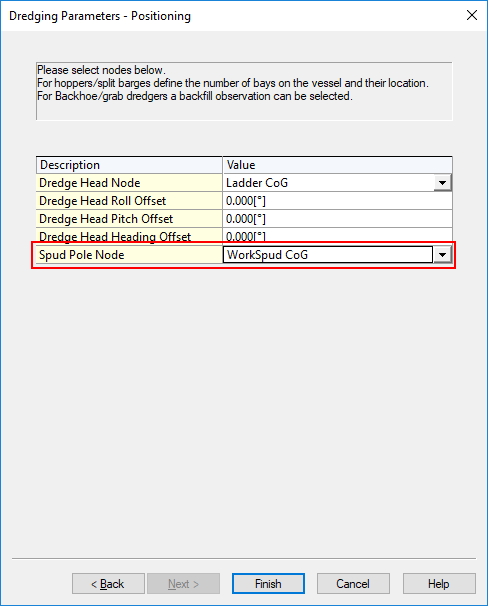
Work Spud Information
The work spud information is computed using the position of the spud node as selected in the 'Dredging Parameters - Positioning' dialog in the Database Setup Program.
Project Grid Convergence
The convergence field uses the following convention: Convergence = True bearing - Grid bearing.
Spare Fields
The spare fields are currently not used and therefore remain 0.0.
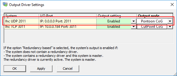
System Interfacing
The driver is normally connected to the DigiSys system using a network connection and uses the UDP protocol as means of communication. The driver is redundancy enabled.
This means that the driver will adhere to the settings as found in the 'Controller - Output Driver Settings' dialog as shown below:
System Configuration
The DigiSys system should be configured to use the same UDP port as set in the Qinsy template database.
Qinsy Configuration
Database setup
The driver is able to extract information for the following system types from the input message:
Position System
The following absolute positions are available from the input message:
-
Center cutter
-
Cut point
-
Calibration point
-
Work spud tip
-
Auxiliary spud tip
-
Starboard anchor
-
Port anchor
In order to decode any of these absolute positions:
-
Add a Position Navigation System to your template and select the driver "Network - IHC Dredging (DigiSys)".
-
The port number should be the same as in the DigiSys system. By default this will be port 2011.
-
The IP address should be 0.0.0.0 unless we want to send to a specific IP address.
-
The maximum update should be set to the required output message rate. Normally this will be 0.200 s (= 5 Hz)
-
Select for Horizontal and Vertical datum the survey datum.
-
Select the appropriate value for the 'Receiver number' field.
Available are:
|
Receiver number |
Position |
|---|---|
|
CentCutter |
Center cutter |
|
CutPoint |
Cut point |
|
CalPoint |
Calibration point |
|
WorkSpudTD |
Work spud tip |
|
AuxSpudTD |
Auxiliary spud tip |
|
AnchorSB |
Starboard anchor |
|
AnchorPS |
Port anchor |
Heading System
The driver is capable of decoding the pontoon heading from the input message.
In order to decode the pontoon heading from the input message:
-
Add a Gyro and Compass system to your template and select the driver "Network - IHC Dredging (DigiSys)"
-
The port number should be the same as in the DigiSys system. By default this will be port 2011.
-
The IP address should be 0.0.0.0 unless we want to send to a specific IP address.
-
The maximum update should be set to the required output message rate. Normally this will be 0.200 s (= 5 Hz).
-
Set the appropriate value for the 'Slot number 1' field.
Available are:
|
Slot number 1 |
Heading for object |
|---|---|
|
HdgPontoon |
Pontoon |
|
HdgLadder |
Ladder |
|
HdgSpud1 |
Main Spud |
|
HdgSpud2 |
Auxilary Spud |
|
HdgStbd |
Starboard Anchor |
|
HdgPort |
Port Anchor |
|
HdgCutter |
Cut Point |
|
HdgCalib |
Calibration |
|
HdgCenter |
Cutter Center |
|
HdgSafety |
Safety Heading |
|
Hdg01 - Hdg10 |
Future Expansion |
Remark: All possible slot numbers result in the same value for the heading but they may be used to create headings for all mentioned objects.
USBL system
The driver is capable of decoding a number of relative positions from the input message:
-
Center cutter
-
Cut point
-
Calibration point
-
Work spud tip
-
Auxiliary spud tip
All relative positions use the APP point as a reference and are present in Qinsy as USBL observations.
In order to decode any of these relative positions:
-
Add a USBL System to your template and select the driver "Network - IHC Dredging (DigiSys)".
-
The port number should be the same as in the DigiSys system. By default this will be port 2011.
-
The IP address should be 0.0.0.0 unless we want to send to a specific IP address.
-
The maximum update should be set to the required output message rate. Normally this will be 0.200 s (= 5 Hz)
-
On the first 'USBL system Parameters' page select the APP node as Reference Node.
-
Set the following fields in the 'Corrections Already Applied to Data' section:
-
Set the 'Roll' field to 'None' to indicate that no roll correction was applied in the DigiSys system.
-
Set the 'Pitch' field to 'None' to indicate that no pitch correction was applied in the DigiSys system.
-
Set the 'Heading' field to 'None' to indicate that no heading correction was applied in the DigiSys system.
-
-
On the 'USBL Targets' page add the appropriate nodes as USBL targets and set the correct 'Slot 1' field.
Available are:
|
Slot 1 |
Position |
|---|---|
|
CentCutter |
Center Cutter |
|
CutPoint |
Cut point |
|
CalPoint |
Calibration point |
|
WorkSpudTD |
Work spud tip |
|
AuxSpudTD |
Auxiliary spud tip |
Pitch Roll Heave Sensor
The system is capable of decoding two Pitch Roll Heave Sensors from the input message:
-
Pontoon (roll & pitch only)
-
Work spud (roll & pitch only)
In order to decode any of these Pitch Roll Heave Sensors:
-
Add a Pitch Roll Heave Sensor to your template and select the driver "Network - IHC Dredging (DigiSys)".
-
The port number should be the same as in the DigiSys system. By default this will be port 2011.
-
The IP address should be 0.0.0.0 unless we want to send to a specific IP address.
-
The maximum update should be set to the required output message rate. Normally this will be 0.200 s (= 5 Hz).
-
Select the appropriate value for the 'Slot' field. Available are:
|
Slot |
Pitch Roll Heave |
|---|---|
|
VruPontoon |
Pontoon Roll & Pitch |
|
VruSpud |
Work spud Roll & Pitch |
Tide Gauge
The driver is capable of decoding the DigiSys used tide measurement from the input message.
In order to decode the tide measurement from the input message:
-
Add a Tide Gauge system to your template and select the driver "Network - IHC Dredging (DigiSys)"
-
The port number should be the same as in the DigiSys system. By default this will be port 2011.
-
The IP address should be 0.0.0.0 unless we want to send to a specific IP address.
-
The maximum update should be set to the required output message rate. Normally this will be 0.200 s (= 5 Hz).
-
On the next page add a Tide observation and connect to the correct node.
-
The 'Slot 1' field on the this page should be set to 'Tide'
Miscellaneous System
The driver is capable of decoding a number of miscellaneous observations from the input message:
-
Spud carriage position
-
Cutter head identifier
-
10 User configurable observations
In order to decode any of these miscellaneous observations:
-
Add a Miscellaneous System to your template and select the driver "Network - IHC Dredging (DigiSys)".
-
The port number should be the same as in the DigiSys system. By default this will be port 2011.
-
The IP address should be 0.0.0.0 unless we want to send to a specific IP address.
-
The maximum update should be set to the required output message rate. Normally this will be 0.200 s (= 5 Hz).
-
On the next page add a Generic observation and set the appropriate observation properties.
-
Select the appropriate value for the 'Slot 1' field.
Available are:
|
Slot 1 |
Observation |
|---|---|
|
CutterHead |
Cutter head identifier |
|
Spud |
Spud carrier position |
|
ConfOut01 |
User configurable observation 1 |
|
ConfOut02 |
User configurable observation 2 |
|
ConfOut03 |
User configurable observation 3 |
|
ConfOut04 |
User configurable observation 4 |
|
ConfOut05 |
User configurable observation 5 |
|
ConfOut06 |
User configurable observation 6 |
|
ConfOut07 |
User configurable observation 7 |
|
ConfOut08 |
User configurable observation 8 |
|
ConfOut09 |
User configurable observation 9 |
|
ConfOut10 |
User configurable observation 10 |
Underwater Sensor
The driver is capable of decoding the pontoon draft from the input message.
In order to decode the pontoon draft from the input message:
-
Add an Underwater Sensor to your template and select the driver "Network - IHC Dredging (DigiSys)".
-
The port number should be the same as in the DigiSys system. By default this will be port 2011.
-
The IP address should be 0.0.0.0 unless we want to send to a specific IP address.
-
The maximum update should be set to the required output message rate. Normally this will be 0.200 s (= 5 Hz).
-
The 'Slot number 1' field on the next page should be set to 'Draft'.
Dredge Sensor
The driver is capable of decoding a number of dredge observations from the input message:
-
Mixture density
-
Mixture velocity
In order to decode any of these dredge observations:
-
Add a Dredge Sensor to your template and select the driver "Network - IHC Dredging (DigiSys)".
-
The port number should be the same as in the DigiSys system. By default this will be port 2011.
-
The IP address should be 0.0.0.0 unless we want to send to a specific IP address.
-
The maximum update should be set to the required output message rate. Normally this will be 0.200 s (= 5 Hz).
-
On the next page add an observation and set the appropriate observation properties.
-
Select the appropriate value for the 'Slot 1' field.
Available are:
|
Slot 1 |
Observation |
|---|---|
|
Velocity |
Mixture velocity |
|
Density |
Mixture density |
Rotation Angle Sensor
The driver is capable of decoding the ladder angle from the input message.
In order to decode the ladder angle from the input message:
-
Add a Rotation Angle Sensor to your template and select the driver "Network - IHC Dredging (DigiSys)"
-
The port number should be the same as in the DigiSys system. By default this will be port 2011.
-
The IP address should be 0.0.0.0 unless we want to send to a specific IP address.
-
The maximum update should be set to the required output message rate. Normally this will be 0.200 s (= 5 Hz).
-
On the next page add a Rotation-X observation and set the appropriate observation properties.
-
The 'Slot number 1' field on the next page should be set to 'Ladder'.
Output System
The driver is capable of sending a message containing the information required by the DigiSys system.
In order to send the output message to DigiSys:
-
Add an Output System to your template and select the driver "Network - IHC Dredging Positions (DigiSys)"
-
The port number should be the same as in the DigiSys system. By default this will be port 2011.
-
The IP address should be 0.0.0.0 unless we want to send to a specific IP address.
-
The maximum update should be set to the required output message rate. Normally this will be 0.200 s (= 5 Hz).
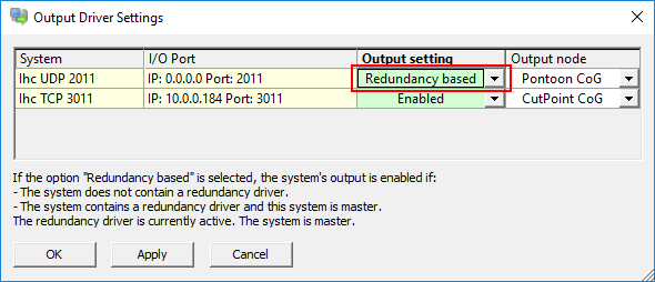
-
In case multiple Qinsy systems are combined in a redundant setup set the 'Data output' field to 'Redundancy based' in order to enable the redundancy feature.
Qinsy Online
Once the template has been taken online the driver does not show any UI.
The I/O may be checked by monitoring the decoded information in an Observation Physics or Generic display.
The position of the output node as selected in the Controller is used for the APP easting, northing & height fields as found in the output message: