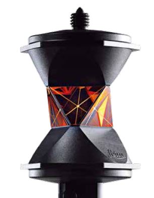
Description
Driver for Leica Nova Total/Multi Station Series, using the GeoCOM protocol and a direct cable connection.
Driver to decode range observation and both horizontal and vertical angles measured by the Leica unit. The actual interrogation of the Leica station is done on every fix update as defined in the Qinsy Controller.
|
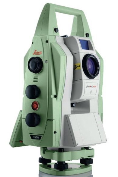
MS50 |
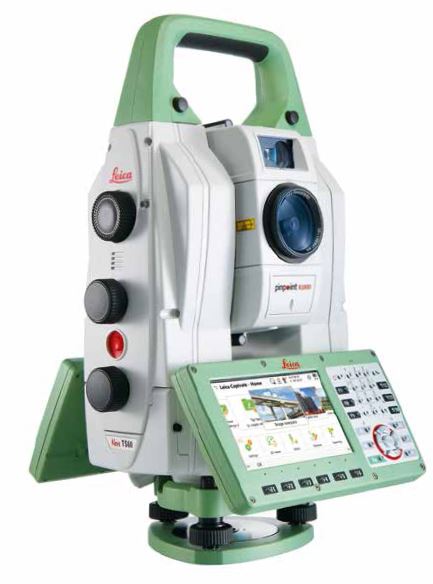
TS60 |
Prism |
|---|---|---|
|
|
|
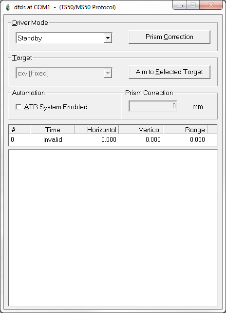
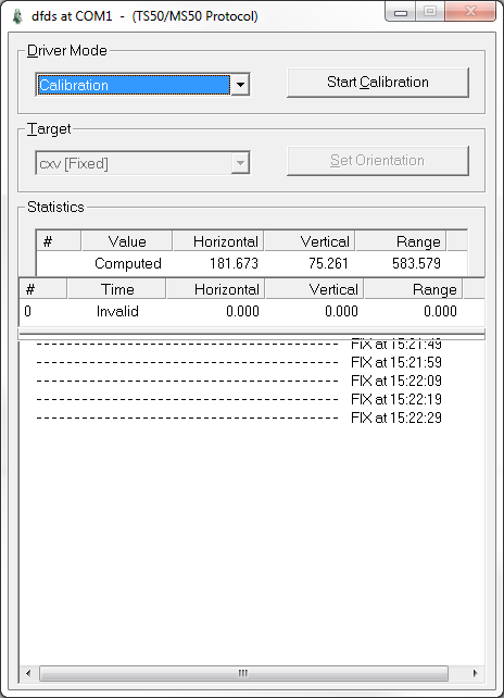
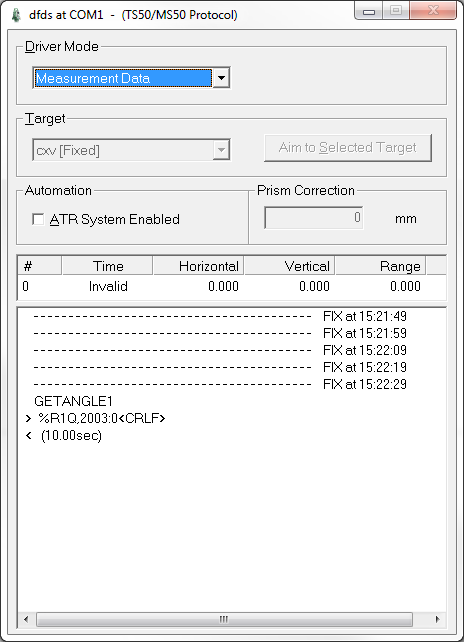
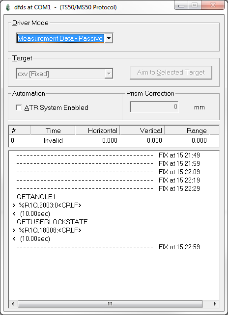
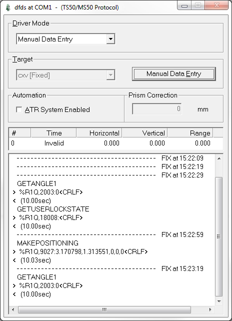
Online, the Leica driver starts up with a user interface window, allowing a user to change the driver mode (standby, calibration, measurement data, and manual data entry), select (and aim to) a target prism, and enable Automatic Target Recognition (ATR).
Driver Information
|
Driver |
Leica Nova TS/MS Series (GeoCOM) |
Interface Type |
Serial |
Driver Class Type |
Interrogate |
|---|---|---|---|---|---|
|
Yes |
Input / Output |
Input (two-way) |
Executable |
DrvLeicaTPS1000UI.exe NOVA |
|
|
Related Systems |
|
||||
|
Related Pages |
|||||
Decoding Notes
The decoded vertical and horizontal angle values are converted to degrees. The distance measurements are already in meters. The decoded horizontal angle is with respect to the horizontal orientation in the Leica theodolite (in the projection grid), and the vertical angle is the zenith angle. Qinsy is expecting true heading and elevation angle, which means (1) that the orientation of the theodolite must be set before the actual measurements are done, and (2) that the C-O values with the observation definitions must be used to get true headings and elevation angles.
The quality indicator of the observations reflect the reply codes (negative for errors) from the Leica. These codes are visible at the bottom of the driver window. Manual data entries have a quality indicator of +0.99.
Interfacing Notes
Communication between the Leica Station and Qinsy can be done using two-way RS232 cable. It is recommended to use a dedicated Leica GEV261 cable:
One side of this cable is a Lemo plug that goes straight into the station socket, the other side is a 9 pin RS-232 connector that should go to a dedicated Qinsy serial COMport. The cable end may also be split with a USB connector, which can be used in the Qinsy or other computer by Leica's Simulator Control Software.
To set the baudrate, use the Connection Wizard of the SmartWorx Viva software on the stations display: Go to the main home page, select 3) Instrument Connections..., Select 3) Connections..., Start the CS Connection wizard, Select a software other than SmartWorx Viva, Connect using Cable RS232, Select the desired baudrate settings.
Database Setup
Scenario 1): Your Leica is stationed on a fixed location, preferably mounted on a tripod, with known co-ordinates.
Scenario 2): Your Leica station is mounted on a moving object, positioned dynamically by external GNSS, Motion and Heading sensors.
In both scenarios the distance and angles are measured to a prism which is mounted on another object.
Goal is to determine the co-ordinates of this object.
For scenario 1)
-
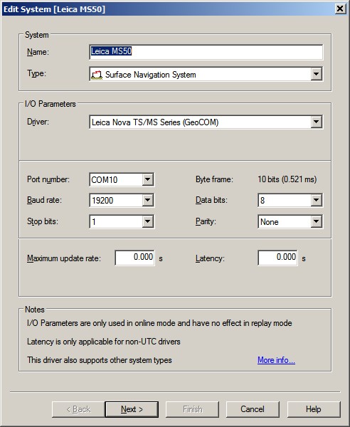
Add a Surface Navigation System in your template setup and select driver "Leica Nova TS/MS Series (GeoCOM)".
-
On the second wizard page, select for the object the fixed node that represents the tripod location.
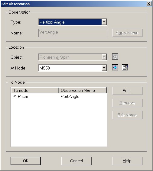
Add three observations: A Range observation for the distance measurement, a Bearing (True) observation for the Horizontal Angle measurement and for the last a Vertical Angle observation.
Select for all three observations the same 'At Node' (the tripod location) and the same 'To Node' (the prism object).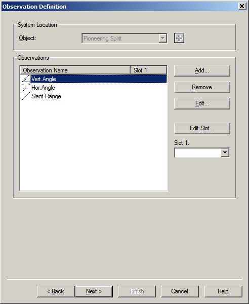
-
Leave the Slot Id's empty, and proceed to the third wizard page, the Observation Parameters.
Set the unit for the two angle observations to Degrees, and for the range observation to Meters.
Important is to change the following default Vertical Angle observation properties in order to convert Leica's orientation convention to Qinsy:
- Fixed C-O: -90.0 (minus ninety)
- Scale factor: -1.0 (minus one)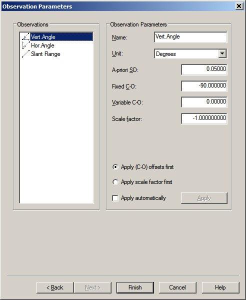
For scenario 2)
-
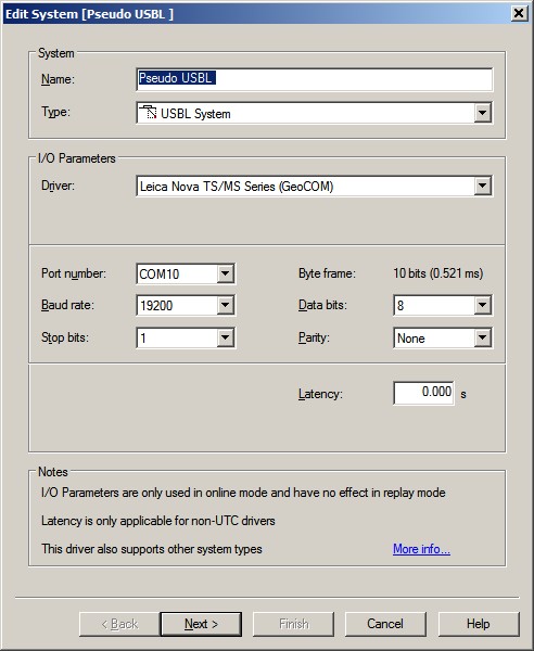
Add a USBL System to your template setup and select driver "Leica Nova TS/MS Series (GeoCOM)".
-
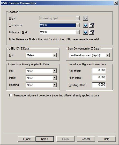
On the second wizard page select the object which the station is mounted on, and for the Transducer and Reference Node the station node location.
Important is to change the Correction Already Applied to Data setting:
- Roll: None
- Pitch: None
It is recommended to mount the Leica station on your object with the horizontal angle of 0° (zero degree) pointing to the bow of the object, as close as possible.
The remaining difference between the horizontal angle 0° reading and the actual bow direction should be entered in the Heading offset field of the Transducer Alignment Corrections. -
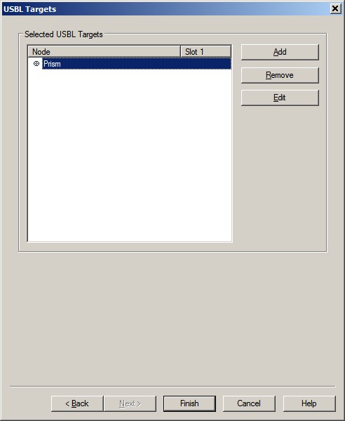
Skip the third wizard page and on the last page select the Add button and select the prism node location. Leave the Slot also empty.
Online
The Leica driver