
Description
Driver for Leica TPS1000 Series Theodolites, using the GeoCOM protocol and a direct cable connection.
Driver to decode range observation and both horizontal and vertical angles from a Leica theodolite.
The actual interrogation of the Leica theodolite is done on every fix update as defined in the Qinsy Controller.
Online, the Leica driver starts up with a user interface window, allowing a user to change the driver mode (standby, calibration, measurement data, and manual data entry), select (and aim to) a target prism, and to change certain sensor settings, such as Automatic Target Recognition (ATR), backlight, cross-wire light.
The user interface window will show the user selections, the prism correction, the decoded observations and both the general and data reply codes from the theodolite.
When the Leica driver is in calibration mode, the differences (mean and standard deviation) between the observed and computed observations are displayed.
After a calibration is done, the computed horizontal orientation can be set to align the Leica to grid north.
Driver Information
|
Driver |
Leica TPS1000 Series Theodolite (GeoCOM) |
Interface Type |
Serial |
Driver Class Type |
Interrogate |
|---|---|---|---|---|---|
|
No |
Input / Output |
Input (two-way) |
Executable |
DrvLeicaTPS1000UI.exe |
|
|
Related Systems |
|||||
|
Related Pages |
|||||
Decoding Notes
The decoded angle values are converted to degrees. The distance measurements are already in meters. The decoded horizontal angle is with respect to the horizontal orientation in the Leica theodolite (in the projection grid), and the vertical angle is the zenith angle.
Qinsy is expecting true heading and elevation angle, which means (1) that the orientation of the theodolite must be set before the actual measurements are done, and (2) that the C-O values with the observation definitions must be used to get true headings and elevation angles.
The quality indicator of the observations reflect the reply codes (negative for errors) from the Leica. These codes are visible at the bottom of the driver window. Manual data entries have a quality indicator of +0.99.
The prism correction as used for the range is obtained from the Leica whenever another target is selected.
System Configuration
The Leica theodolite must be set to use the GeoCOM interface protocol. This setting can be found under its "Extra" menu option. The first time that a prism is tracked, the theodolite must be manually aimed at the target.
After the horizontal orientation has been calibrated and set, the driver can automatically aim the Leica at prisms on other fixed target nodes or at prisms on variable nodes that have just been tracked before.
Interfacing Notes
Leica interface parameters can be set using the keyboard, and are by default 9600 baud, 8 data bits, 1 stop bit, no parity.
The GeoCOM protocol uses an ordinary two-way RS232 cable.
Database Setup
-
Add an "Object" for the target unit.
-
Add a "Fixed Node" for the Leica station setup node.
-
Add a "Variable Node" (on the target object) for the target unit to be used for online positioning. Be sure to enter its offsets.
-
Add a "Surface Navigation System" with driver "Leica TPS1000 Series Theodolite" and enter the interfacing parameters and latency value.
-
Add one or more sets of three "Observations", for the distance (range) and for the horizontal and vertical angles. Be sure to select the same station node for the fixed "At Node", and the same target node for the variable "To Node" for one set of corresponding observations. Enter one set of observations for each of the variable target prisms to which the Leica will be measuring.
-
Add an additional set of observations with "CAL" in the "Slot 1" field, if calibration observations have to be logged. See below.
Range. Observation unit for the range should be "meters". Observation type is "range". A physical horizontal offset, in case of a ring of prisms, should be entered as a correction to the range if they are not set in the Leica. Calibration corrections (and prism offset) for the range can be entered as "Observation Properties".
Angles. Observation units for the two angles should be "degrees". The observation type for the horizontal angle is "bearing, true", whereas the zero direction in the Leica theodolite (after calibration) is a grid bearing. Therefore, the grid meridian convergence at the fixed Leica setup node must be entered as "Fixed C-O" or "Variable C-O" value. This convergence can be calculated using the "Test geodetical paremeters" option.
The observation type for the vertical angle is "vertical angle" which must be an elevation angle. Since the Leica driver will normally output a zenith angle, the "Fixed C-O" value must be set to -90 degrees (minus) and the "Scale factor" must be set to -1 (minus), because of the order in which Qinsy applies these values.
Calibration Observations. Fixed nodes are also available as target in the Leica driver, even if there are no observations to these targets. However, in order to log and use such measurements to unconnected fixed targets, add a new dummy "Object" to the database with a variable node, for example just the reference node. In the Leica system setup, add a new set of observations (range, horizontal angle, vertical angle) from the fixed Leica setup node to this new dummy variable node, and enter "CAL" as slot number. When a fixed node is selected as target and there are no other connected observations found in the database setup, the driver will transfer the three decoded measurements to the set of observations with "CAL" as slot number. The observations can be used in an computation since they are defined to a variable node so that comparisons can be made between the observed position and known positions obtained from the defined fixed nodes.
Online
The Leica driver has four modes in which different options for online communication are available.
Standby. In this mode, the Leica will not be interrogated for measurement data and data will not be updated.
However, it is possible to automatically aim the Leica theodolite, when a target is selected that is either a fixed node or a variable node with a valid set of observations (i.e. that has been measured before), or to enable-disable the ATR system, keyboard backlight, or reticillum light (illumination of cross-wires).
Prism Correction. In standby mode, it is possible to set the prism correction that is used by the Leica as follows. Select target. Press button "Prism Correction". Enter the appropriate correction value in the edit box. Press button "Set Prism Correction" to upload the value to the Leica. The edit box is then reset to 0 and the Leica is interrogated to get its new prism correction. The returned prism correction value is then displayed. Press button "Disable Correction" to quit this option. The "Aim to Selected Target" button becomes visible.
Notes. The correction value, together with the target node name, is saved in the Windows registry. The next time that this option is enabled, the driver will look for the previously entered value for the selected target. Users can use "regedit" to add, enter, export and/or import new entries, so that a "table" becomes available. The prism correction as used for the range is obtained from the Leica whenever another target is selected.
Calibration. A list control showing calibration statistics becomes visible. After pressing "Start Calibration", the current list of observations is cleared and a new list of observations is started. The computed observations are shown together with the mean and the standard deviation (1-sigma) of the C-O values. After pressing the "Stop Calibration" button, the computed horizontal orientation can be uploaded to the Leica theodolite.
Measurement Data. On every fix update, the Leica is interrogated and the measurement data are updated.
Manual Data Entry. On every fix update, the manually entered set of observations is updated to Qinsy.
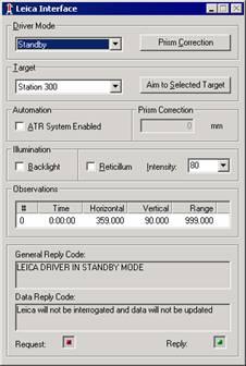
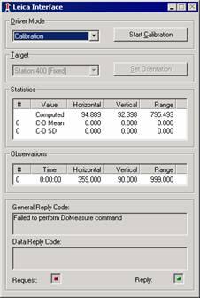
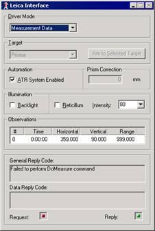
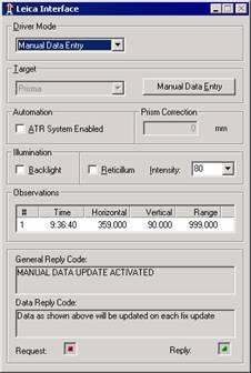
4 different driver modes - Standby, Calibration, Measurement Data, Manual Data Entry