
Description
Driver to decode laser data from Voyis Insight Pro underwater laser scanner.
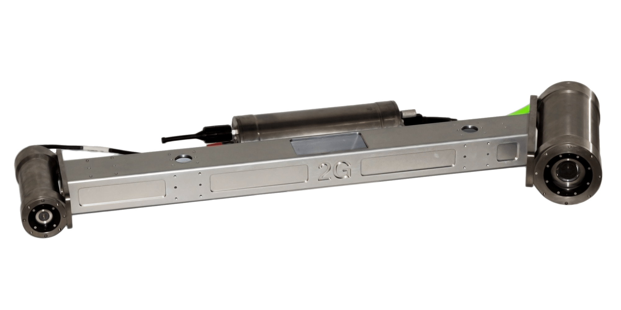
Note that this scanner is formerly know as 2G Robotics ULS-500 PRO before the company 2G Robotics was acquired by Voyis.
Driver Information
|
Driver |
2G Robotics ULS-500 PRO |
Interface Type |
UDP |
Driver Class Type |
UdpClient |
|---|---|---|---|---|---|
|
Yes |
Input / Output |
Input |
Executable |
DrvLAS.exe |
|
|
Related Systems |
|||||
|
Related Pages |
|||||
Decoding Notes
Data is always broadcast via UDP network. Use a fast (Gigabit) network card, due to the enormous amount of data to be expected
The ULS 500 PRO publishes up to 75 profiles per second, where each profile contains 2048 data points.
(Notice that the older ULS 500 published up to 30 profiles per second, where each profile contained 1400 data points)
Each profile packet format is based on the LAS 1.2 format, which will not be further described in this document.
More information can be found at http://www.asprs.org/a/society/committees/standards/asprs_las_format_v12.pdf.
The driver is configured as a Multibeam System and creates 'multibeam' x/y/z observations.
('multibeam' versus 'laser scanning'-terminology: ping = scan = profile = swath = line, footprint = pixel = point = pulse)
Decoding
The following information will be decoded from each point:
|
X/Y/Z |
Relative co-ordinates to the center of the laser system in the scanners own co-ordinate frame |
|---|---|
|
Intensity |
Strength of the laser return. A value between 0 and 65535 (0 = low) |
|
Quality |
Measure of confidence in the data point based on the detected data point intensity compared to the background intensity (noise).
|
|
Time |
UTC time |
About X/Y/Z
The decoded X/Y/Z values are defined in the scanners own co-ordinate frame, which is not the same as the standard frame commonly used in the hydrographic world.
Especially when the scanner is different mounted on your underwater object: pitched backward, or pitched forward, or horizontally looking forward, etc, etc.
This makes it difficult to figure out the correct calibration mounting offsets in order to convert the values into the 'Qinsy' co-ordinate frame (where +X is starboard, +Y is bow, +Z is height)
See the DM-0418#advanced_sectionsection how to convert the scanners own co-ordinate frame into the 'Qinsy' co-ordinate frame.
About Intensity and Quality
The Quality value is the Intensity value subtracted the smallest value in the analysis window, which will be the background light level in most cases.
For example, in cloudy water the intensity might be bright, but quality is low. Therefore both figures can be used for validation to exclude noise.
See the DM-0418#advanced_section section for more information about this
Database Setup
Internally the driver is treated as a multibeam system, creating 'multibeam' x/y/z observations, therefore you will find the laser system drivers under category type Multibeam Echosounders.
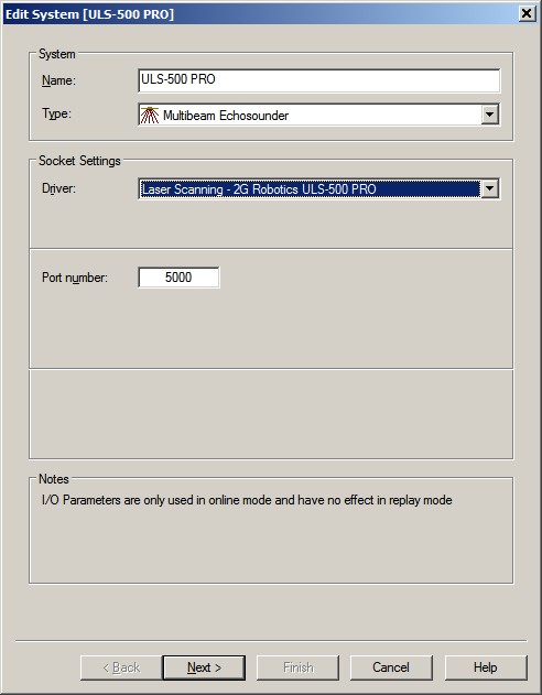
Edit System Wizard
-
Add a Multibeam Echosounder system to your template setup and select from the list driver "Laser Scanning - 2G Robotics ULS-500 PRO".
-
The Port number should be set to the UDP port number the unit will send its messages to.
Multibeam Echosounder Parameters
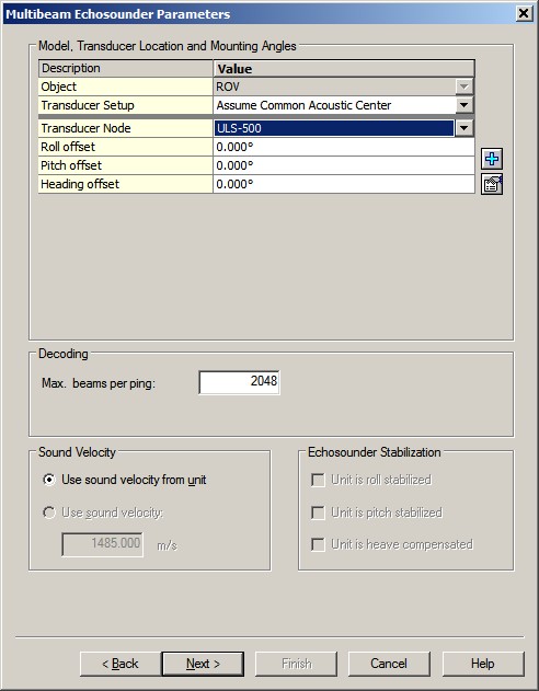
-
Important are the Transducer Node location and Mounting Angles (offsets) on the second wizard page.
The exact values for the roll, pitch and heading offsets should be established with a calibration procedure.Before such a calibration one should use values as accurate as possible.
-
Leave the maximum beams per ping value to 2048.
A higher value is allowed (e.g. 9999) but not a lower value.
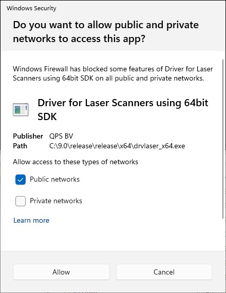
Windows Firewall
The very first time you go online Windows may pop up a security message:
Please make sure to Allow access.
If you forgot to do this, or if you are not sure if this has been done, you may want to follow the steps as described in the Additional Info or Trouble Shooting section about Windows firewall.
This driver does not have any user-interface to control the system from within Qinsy (e.g. for starting and stopping the scanner).
Once the scanner is underwater it should stream the data straight away, so it is recommended to use an IO Alert Display, Raw Multibeam Display and Generic Display to see if data is coming in and is decoded correctly:
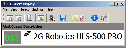
You can setup an IO alert to see if data is coming in via the UDP network, or not.
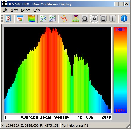
Use a Raw Multibeam Display to monitor e.g. the reported Intensity distribution.
This is a good indication to see if a target is being scanned or not: e.g. you'll get a huge distribution of low intensity values when only seawater is being scanned, and no targets.
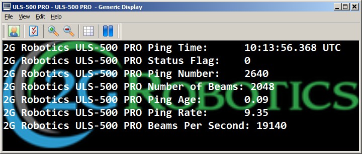
Use a Generic Display when you want to monitor general information, like the current Ping Rate, the Number of Beams (hits) of the last profile (scan), the number of Beams Per Second, etc.
When the Status Flag value is 2 it means that the timestamp from the data is being used. If it is zero then the time of arrival is used.
Important is to see a low Ping Age value (around zero), especially when the Status Flag is 2, otherwise you may have a timing issue.
The driver does not have any user-interface to control the scanner with additional settings while scanning.
However, there are some command-line parameters which an advanced user may tweak that will affects the online behavior.
Control about the Intensity
The driver will always receive for every profile the returns for all 2048 hits. Even when scanning no targets and only seawater.
So if you don't want to receive, accept and store noise, use a minimum intensity threshold. This will exclude all data points with a less intensity value.
To exclude the most part of the noise you can safely use an intensity threshold value of 100. Real underwater objects (pipelines, templates, shipwrecks, etc) will have a much higher intensity value, e.g. > 1000, up to 65535.
Cmd-line parameter: MIN_I=xxx, where xxx is the minimum threshold. Default it will be 400. If you omit this cmd-line parameter, it will be 5. If you set it to 0 (zero), then all points will be accepted.
Control about the Quality
As mentioned above for the Intensity, the same accounts for the reported Quality value. This will be a value between 0 and 255, but low values normally means no real data (noise, seawater).
Use a minimum Quality threshold. This will exclude all data points with a less quality value.
Cmd-line parameter: MIN_Q=xxx, where xxx is the minimum threshold. Default it will be 1. If you omit this cmd-line parameter, it will be 1. If you set it to 0 (zero), then all points will be accepted.
Control about the default orientation
Use the following CASE-SENSITIVE cmd-line parameter to convert the LAS internal co-ordinate system to a more convenient co-ordinate system.
Useful to determine the calibration mounting offsets. I.e. you can leave the Roll, Pitch and Heading offsets around zero, therefore values like +270, or -90 are not needed anymore.
|
Cmd-line |
X |
Y |
Z |
Comment |
|---|---|---|---|---|
|
XYZ |
+X |
+Y |
+Z |
Default (Same as no cmd-line) - No conversion |
|
XYz |
+X |
+Y |
-Z |
Note that the driver LAS parser swaps the Z, so use this to get exactly the co-ordinate system as defined by LAS |
|
xyz |
-X |
-Y |
-Z |
|
|
xYZ |
-X |
+Y |
+Z |
|
|
XyZ |
+X |
-Y |
+Z |
|
|
Xzy |
+X |
-Z |
-Y |
|
|
xzY |
-X |
-Z |
+Y |
|
|
xZy |
-X |
+Z |
-Y |
|
|
XZY |
+X |
+Z |
+Y |
When the unit is mounted Pitched Backward |
|
XZy |
+X |
+Z |
-Y |
When the unit is mounted Pitched Forward |
|
YZx |
+Y |
+Z |
-X |
When the unit is mounted Horizontal Forward looking |
|
yXz |
-Y |
+X |
-Z |
|
|
Yxz |
+Y |
-X |
-Z |
|
|
yxZ |
-Y |
-X |
+Z |
|
|
YXZ |
+Y |
+X |
+Z |
|
|
yzx |
-Y |
-Z |
-X |
|
|
YzX |
+Y |
-Z |
+X |
|
|
yZX |
-Y |
+Z |
+X |
|
How To Overrule these Parameters?
Qinsy v9.1, v8.18 or older
DRIVERS.IO
In order to overrule the default setting as mentioned above you may modify the cmd-line parameter(s) in file DRIVERS.IO.
Example:
200180, Laser Scanning - LAS                                          , DrvLAS.exe MIN_I=10                                                     , 13000400000014001100000000, 0, 2
200200, Laser Scanning - 2G Robotics ULS-500 PRO                      , DrvLAS.exe MIN_I=400 MIN_Q=1                                            , 13000400000020481100000000, 0, 2
200201, Laser Scanning - 2G Robotics ULS-500 PRO (Pitched Forward)    , DrvLAS.exe MIN_I=400 XZy                                                , 13000400000020481100000000, 0, 2
200202, Laser Scanning - 2G Robotics ULS-500 PRO (Pitched Backward)   , DrvLAS.exe MIN_I=400 XZY                                                , 13000400000020481100000000, 0, 2
200203, Laser Scanning - 2G Robotics ULS-500 PRO (Horizontal Forward) , DrvLAS.exe MIN_I=400 YZx                                                , 13000400000020481100000000, 0, 2
-
You can use a normal text editor like Notepad to edit.
-
Copy the attached file to your Public Documents folder, subfolder \QPS\QINSy\Drivers.
For example: C:\Users\Public\Documents\QPS\QINSy\Drivers\DRIVERS.IO -
Be careful, do not modify any other column than the cmd-line parameters behind DrvLAS.exe: MIN_I=xxx MIN_Q=xxx XYZ.
-
When in doubt, please contact QPS to help you.
Qinsy v9.2 or newer
DRIVERS.IO.json
In order to overrule the default setting as mentioned above you may modify the executable_argument(s) in file DRIVERS.IO.json
Example
...
	"id": 200200,
	"description": "Laser Scanning - 2G Robotics ULS-500 PRO",
	"executable": "DrvLAS.exe",
	"executable_arguments": [
		"MIN_I=400",
		"MIN_Q=1"
	],
...
-
You can use a normal text editor like Notepad to edit.
-
Copy the attached file to your Public Documents folder, subfolder \QPS\QINSy\Drivers.
For example: C:\Users\Public\Documents\QPS\QINSy\Drivers\DRIVERS.IO.json -
Be careful: only modify the text fields inside the "executable_arguments" brackets.
-
When in doubt: please contact QPS to help you.