
Description
Driver that decodes bathymetry data, seabed imagery (for raw storage) and water column data from the latest models Kongsberg multibeam echosounders.
Currently the following systems are supported:
-
EM-2040
-
EM-2040C
-
EM-2040M
-
EM-2040P
-
EM-710
-
EM-712
-
EM-302
-
EM-122
For raw data processing the driver can optionally store raw bathymetry and seabed image records in the Qinsy database.
The naming of the driver has been changed in 9.7.0. They used to be:
-
Kongsberg EM2040-EM710-EM712-EM302-EM122
-
Kongsberg EM2040 Head II
Driver Information
|
Driver |
Kongsberg ALL (SIS 4) |
Interface Type |
UDP |
Driver Class Type |
|
|---|---|---|---|---|---|
|
Yes |
Input / Output |
Input |
Executable |
DrvKongsbergEM.exe |
|
|
Related Systems |
Kongsberg ALL (SIS 4) :
Kongsberg Multibeam Controller :
|
||||
|
Related Pages |
|||||
Coding Notes
Driver decodes the following datagrams:
|
Raw Range and Angle 78 (N) |
Bathymetry data |
|
Seabed Imagery 89 (Y) |
Imagery data |
|
Clock (C) |
Clock data |
|
Water Column (k) |
Water column data |
|
Runtime Settings (R) |
Actual PU settings |
If Clock datagrams are not sent then the driver will not decode any data since the Clock datagram is used to identify which head is to be decoded.
The Clock datagram contains the serial number of the main head; this is always the first, port head.
If the second head is to be decoded then the driver will decode the datagram with the serial number not equal to the main serial number.
The decoded Quality has a range between 0 and 254. It is equal to the scaled standard deviation of the range divided by the detected range. Smaller means better quality.
The decode Intensity stands for the backscatter reflectivity in dB.
If a Time Synchronization (previously PPS) system is defined in the setup then the time from the message is used, otherwise the time of arrival is used.
Seabed Imagery will be treated as part of the multibeam system.
The Runtime messages are only decoded for the raw data storage and are not decoded any further.
Extra detections
Extra detections are not supported in this format. They are stored as normal footprints.
The KMALL format (Kongsberg KMALL (UDP multicast) - 20) does give you the option to store these detections as extra detections.
System Interfacing
Qinsy CONTROLLER (Not using SIS)
The EM2040/EM2040C can optionally be controlled from Qinsy with the Kongsberg EM Control Driver.
The other Kongsberg systems (EM122/EM302/EM710/EM712/M3) should be controlled from the Kongsberg SIS Software but obviously the data can be decoded in Qinsy.
The following diagram shows a setup with one EM2040C head:
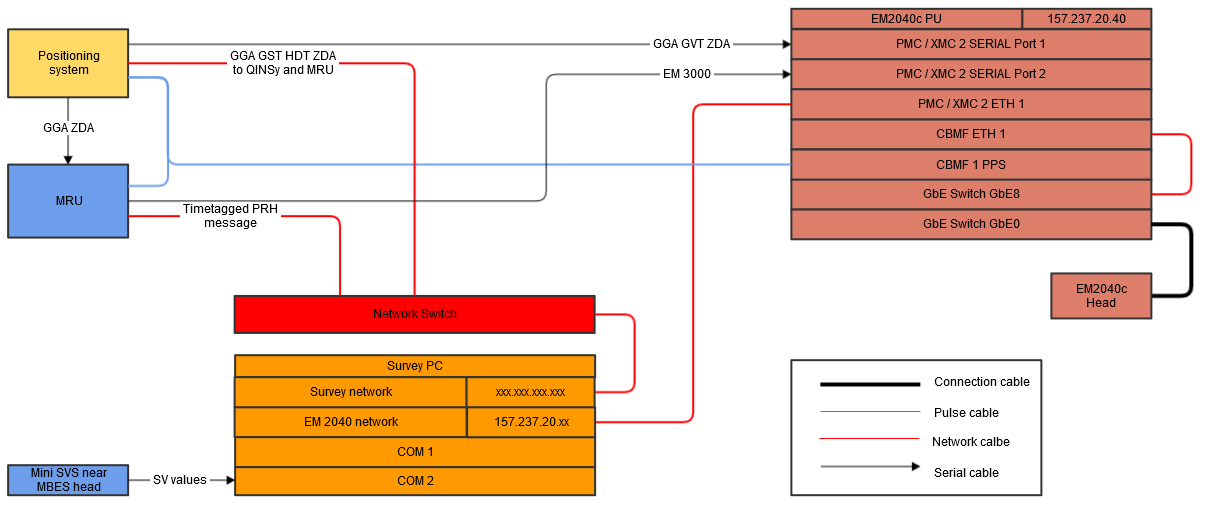
Unknown Attachment
SIS - Qinsy - Single Head
If SIS is used to control the echosounder then the proper output data port and packets should be selected in SIS.
If you use a single head setup, there is no need to use the Data Distribution program Kongsberg has.
Note that there is a fixed port and that you can select in SIS which data needs to be send via that port:
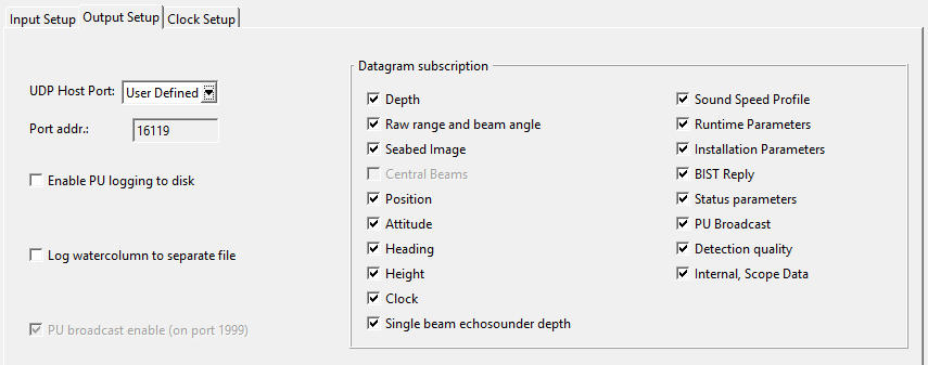
At least the N, Y, C, k datagrams should be selected. The output port number as entered in SIS will have to be entered as the driver network port.
Please add additional dedicated drivers in the Qinsy setup to decode data directly from the systems and not via SIS (as it is sending motion in 1sec bursts):
-
Position
-
Serial:
-
Network:
-
-
Motion
-
Serial
-
Any other format available
-
Network
-
-
Heading
-
Serial
-
Network
-
SIS - Qinsy - Dual Head
This setup if fairly similar to the single head setup except that we need a Kongsberg program called "DataDistribution" to combine the data from the two heads on one dataport.
In case you are running this on the same PC you can set the following items:
-
Source port Head I : 16103 (needs to be double checked)
-
Source port Head II : Unknown
-
Destination port : "Localhost: 2001"
Warning: Package loss
Make sure to only select the messages you need (N, Y, C, k datagrams).
We have seen problems where packets were dropped.
Dual head package loss
A 'Balanced' (default) power plan on the HWS can cause package dropouts from the second head. This can be solved by changing the power plan on the HWS pc from 'Balanced' to 'High Performance' when using a Windows7 pc.
Read more
More information on the transducer offsets can be found in the following Qinsy Knowledge Base document: How-to Kongsberg Multibeam - Reference Position
System Configuration
Preferably a direct cross-over network cable should be used to transfer the data. This will minimize the chances of any dropped packets.
Preferably no programs that re-send the network packets such as Kongsberg DataDistrib are to be used. This is no longer necessary since multiple heads can now be decoded in one Qinsy driver executable.
Dual head package loss
A 'Balanced' (default) power plan on the HWS can cause package dropouts from the second head. This can be solved by changing the power plan on the HWS pc from 'Balanced' to 'High Performance' when using a Windows7 pc.
Auxiliary data
Please note that the driver does not decode auxiliary sensors interfaced into the unit, such as position, motion, heading, etc. These external sensors will have to be interfaced directly to Qinsy as well.
EM2040 Transducer setup
An EM2040 Single Head systems is equipped with one Transmit transducer and one Receive transducer; an EM2040 Dual Head system is equipped with one Transmit transducer and two Receiver transducers.
The RX and TX transducers of the EM2040 can each be oriented normally or reversed. The Heading offset angle should either be around 0° or around 180° when the orientation is reversed. The Receive (RX) transducer is mounted normally (0°) when the connector points to bow and reversed (180°) when it points to stern. For Transmit (TX) transducer this is port (0°) and starboard (180°) respectively. It seems that most EM2040 systems in the field have the RX connector pointing to stern and TX connector pointing to port, so the Multibeamer heading offset should be for the TX 0° and RX 180°. However, all combinations are possible.
Note that for the sake of simplicity of usage in Qinsy it is by far the easiest to mount the transducers with normal, non-reversed, orientation.
Note that for a dual head system with reversed RX transducers (heading offset around 180°) the roll offset should be around -30° for port side and +30° for starboard side, this is exactly opposite to what is common with "normal oriented" systems.
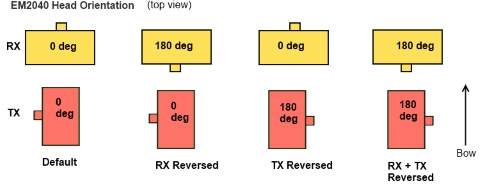
Figure: EM2040 Head Orientation options
The figure above shows the orientation of the EM2040 Transducers and the approximate Multibeam System Heading offset that needs to be entered in Database Setup.
Reversed Sign
If the RX transducer is reversed, the Roll value as determined on the patch test should have a reversed sign (meaning the transfer option can't be used).
Phase Center offsets (PCO) used by Qinsy
The table below represents the PCO applied by Qinsy.
Offsets are in millimeters (stern-bow, port-starboard, up-down). Bow, starboard and up are positive.
|
Device |
Tx PCO |
RX PCO |
Comment |
|---|---|---|---|
|
EM2040C |
40,3.8,6 |
0,-46,6 |
The coordinates are given in the Vessel Coordinate System, where x is forward, y is starboard and z is downward.
|
|
EM2040 |
port: -55,0,12 |
0,11,6 |
|
|
|
center: 13,0,6 |
|
|
|
|
starboard: 55,0,12 |
|
|
|
EM2040M |
port: -104,0,45 |
0,202,62 |
The x,y,z positions for the 3 TX line arrays are relative to the center of the sonar head
|
|
|
center: 0,0,6 |
|
|
|
|
starboard: 104,0,45 |
|
|
|
EM2040P |
port: -104,2,15 |
0,204,32 |
The x,y,z positions for the 3 TX line arrays are relative to the center of the sonar head face.
|
|
|
center: 0,2,6 |
|
|
|
|
starboard: 104,2,15 |
|
|
Acknowledgement: Kongsberg EM Series Multibeam echo sounder EM datagram formats, 850-160692/V July 2016 © Kongsberg Maritime AS
EM2040C Installation Offsets
For the EM 2040C, the TX and RX arrays are integrated into a common sonar head. The transducer arrays are not placed at the center of the sonar head.
The EM 2040C can have one or two sonar heads. For most EM echo sounders separate x,y,z installation parameters are given for the RX and the TX arrays.
For EM 2040C the installation parameters entered by the operator refers to the centre of the face of the sonar head(s).
Acknowledgement: Text by Kongsberg EM Series Multibeam echo sounder EM datagram formats, 850-160692/V July 2016 © Kongsberg Maritime AS
'EM2040C Reference point, the so-called face of the center of the transducer'
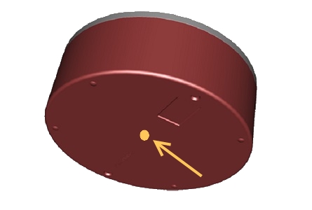
EM2040P Installation Offsets
For the EM 2040P, the TX and RX arrays are integrated into a common sonar head. The transducer arrays are not placed at the center of the sonar head.
For most EM echosounders separate x,y,z installation parameters are given for the RX and the TX arrays.
For EM 2040P the installation parameters entered by the operator refers to a reference point on the face of the sonar head. This point is not marked on the sonar head.
The reference point used is the intersection between two diagonal lines drawn between the bumpers on the sonar head face.
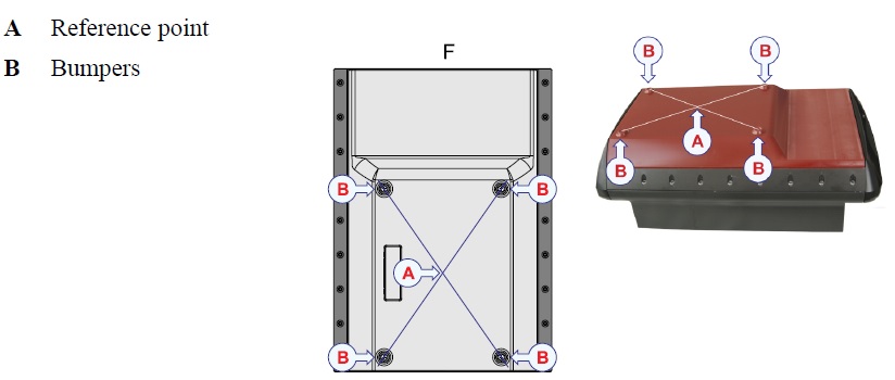
Acknowledgement: Text and Image by Kongsberg EM Series Multibeam echo sounder EM datagram formats, 850-160692/V July 2016 © Kongsberg Maritime AS
Kongsberg Mesotech M3
If you have the M3 sonar head mounted with connector forward, then in Qinsy, the heading offset is 0.
If you have the M3 sonar head mounted with connector aft, then in Qinsy, the heading offset is 180.
What offset you set in the M3 software won’t change the Qinsy offset. So both M3 and Qinsy software have to agree with your physical mounting, AFT, which is backwards, which is 180 offsets on heading.
Qinsy Configuration
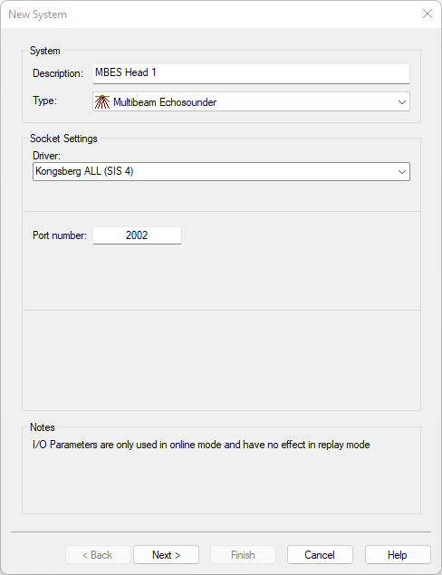
Multibeam System
Main Head
|
Name |
For example: "multibeam head 1" |
|---|---|
|
Type |
Multibeam Echosounder |
|
Driver |
Kongsberg ALL (SIS 4) |
|
Port number |
As setup in the Multibeam PU or SIS |
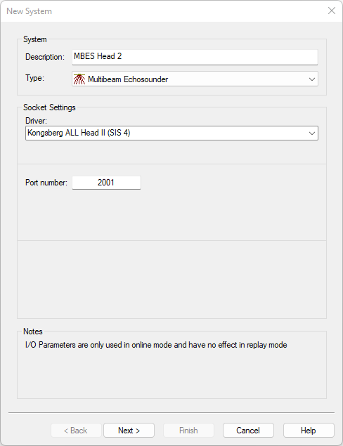
For a dual head EM2040 add a second multibeam system and select driver "Kongsberg EM2040 Head II" in order to decode the second, starboard transducer.
Secondary Head
|
Name |
For example: "multibeam head 2" |
|---|---|
|
Type |
Multibeam Echosounder |
|
Driver |
Kongsberg ALL Head II (SIS 4) |
|
Port number |
As setup in the Multibeam PU or SIS |
Dual Head
Choose the same port number for both drivers. This will make sure that both heads are handled by one driver executable.
-
If SIS is used to control the sounder then select the port number as set in the SIS software.
-
If the Qinsy EM Controller is used then select one of the bathymetry output ports that was set in the Qinsy EM Controller driver user interface, by default 2001 or 2002.
Info
When using SIS for control instead of Qinsy's Kongsberg EM controller, a program called 'DataDistrib MDM400' should be used.
This program comes with SIS. For a dual head the program needs to be used.
Example:
-
From SIS set a user defined output on a UDP port for example: 16103
-
Inside the DataDistrib program you set up as follows:
-
Source port: 16103
-
Destination Port 1: <Qinsy pc IP address>:2001 (for instance, 192.168.101.50:2001)
-
Destination Port 2: <Qinsy pc IP address>:2002 (for instance, 192.168.101.50:2002)
-
-
In Qinsy the EM2040 Head 1 should receive data on port 2001 and Head 2 port 2002
When SIS is running and pinging, in the DataDistrib program you can view the number of packets increasing on source port 16103 meaning data is flowing OK.
For your convenience you may add DataDistrib to the Windows startup processes, so its starts automatically with Windows and cannot be forgotten.
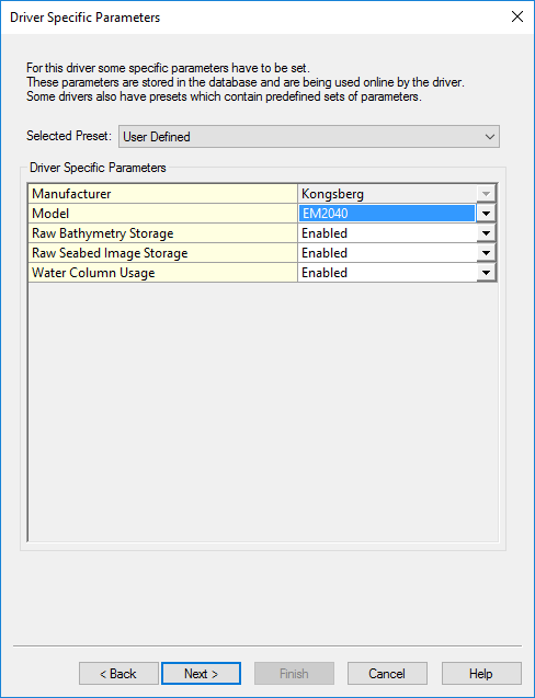
Driver Specific Parameters
|
Selected preset |
Raw Bathymetry Storage |
Raw Seabed Image Storage |
Water Column Usage |
|---|---|---|---|
|
FM Geocoder Toolbox (FMGT) |
|
|
|
|
FM Midwater (FMMW) |
|
|
|
|
FM Geocoder Toolbox (FMGT & FM Midwater (FMMW) |
|
|
|
|
XTF Export |
|
|
|
Info
Please use the Preset so the needed data packages are decoded.
|
Setting |
Option (bold=default) |
Description |
|---|---|---|
|
Manufacturer |
Kongsberg |
|
|
Model |
Other/EM122/EM302/EM710/EM712/EM2040/EM2040C/EM2040M/EM2040P |
For the systems in this list you can now enter the reference point as node. See 'How-to Kongsberg Multibeam - Reference Position' |
|
Raw Bathymetry Storage* |
Disabled/Enabled |
When Enabled the Raw (original) Bathymetry packets (e.g. N) and the Runtime Settings (R) are stored in the database for usage in Fledermaus. |
|
Raw Seabed Image Storage** |
Disabled/Enabled |
When Enabled the Seabed Image (Y) is stored in the database for usage in Fledermaus. |
|
Water Column Usage |
Disabled/Enabled |
When Enabled the Water column data is decoded by the Driver.
|
Multibeam Echosounder Parameters
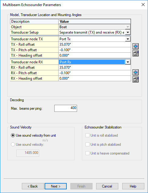
EM2040
For this system the transducers are separate. These should therefore be entered separately.
More info can be found in the "System Configuration" tab.
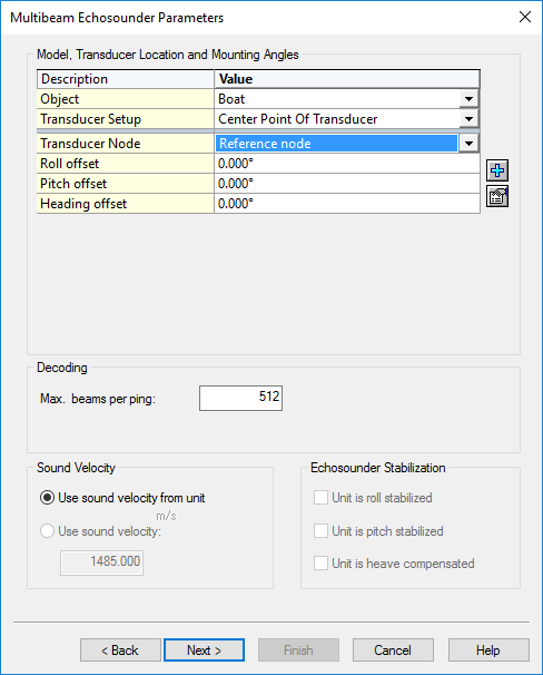
EM2040C / EM2040M / EM2040P
The offset of the transmit and receive transducers are known by Qinsy.
Therefore you only need to enter the Reference node of the Head.
|
Roll/Pitch/Heading offset |
These are the offsets between the reference frame of the Motion sensor (which is usually aligned with the vessel frame) and the reference frame of the multibeam head. (Please also read the System Configuration part of this Drivers Manual for this) |
|---|---|
|
Max. Beams per ping |
This is the maximum amount of points we decode from the multibeam. |
|
Sound Velocity |
We use the sound velocity from the unit (measured near the head). |
|
Echosounder Stabilization |
Not applicable. |
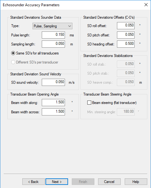
Echosounder Accuracy Parameters
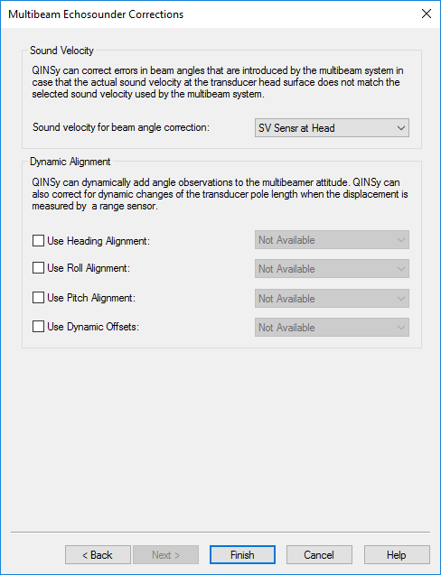
Multibeam Echosounder Corrections
Dual Head
In the Knowledge Base you can find the document 'Kongsberg EM2040 Dual head Calibration'. This explains in more detail how to carry out a calibration.
Miscellaneous System
Some multibeam systems, decoded by this driver, can be controlled from Qinsy using the EMcontroller:
|
EM2040 (single Head) |
|
|---|---|
|
EM2040 (dual Head) |
|
|
EM2040C (single Head) |
|
|
EM2040C (dual Head) |
Output System
To record valid *.all and *.db files (without ping dropouts), we have to start and stop logging via Qinsy, however an output system is required .
Add the XML files in the table below to this location:
C:\Users\Public\Documents\QPS\Qinsy\Drivers\Definitions\Output
|
XML files |
||
|---|---|---|
|
EM-2040 EM-2040M EM-2040P |
||
|
EM-2040C |
||
|
EM-710 |
||
|
EM-712 |
||
|
EM-302 |
||
|
EM-122 |
||
Info
The xml-files above are only visible when logged in to the QPS website, not when viewing the Drivers Manual from the Qinsy Console.
Create an Output system:
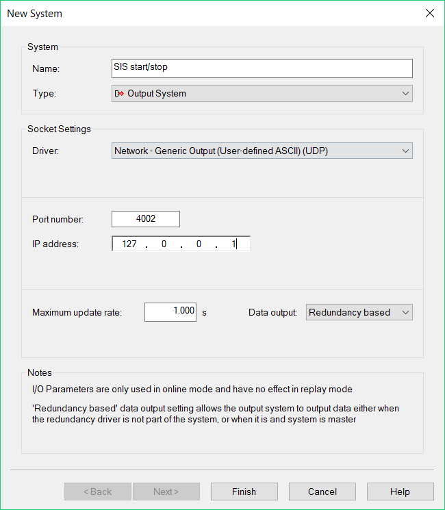
Info
Keep in mind that this has been tested on one pc which ran Qinsy and SIS simultaneously, with IP address 127.0.0.1
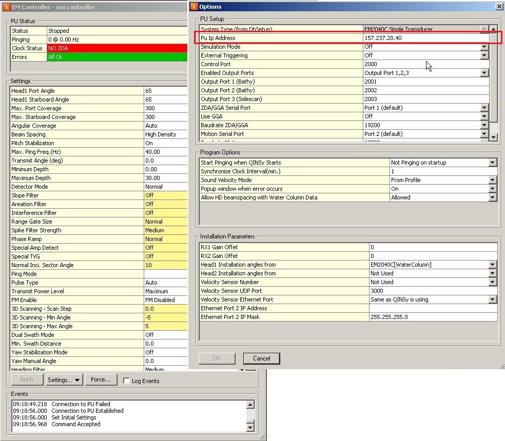
Qinsy Online
Online the EM Controller settings should state the correct PU IP Address for the specific multibeam:
|
Kongsberg Model |
PU IP Address |
|---|---|
|
EM 120 |
157.237.14.60 |
|
EM 122 |
157.237.14.60 |
|
EM 300 |
157.237.14.60 |
|
EM 302 |
157.237.14.60 |
|
EM 710 |
157.237.2.71 |
|
EM 1002 |
157.237.15.60 |
|
EM 2000 |
157.237.2.58 |
|
EM 3000 |
157.237.2.58 |
|
EM 3002 |
157.237.2.61 |
|
EM 2040 |
157.237.20.40 |
|
EM 2040C |
157.237.20.40 |
|
EM 2040M |
157.237.20.40 |
|
EM 2040P |
157.237.20.40 |
This can be set in the Options menu of the EM Controller:
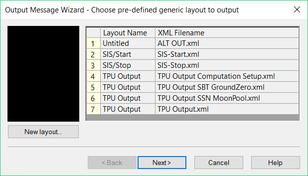
Generic Output
Add the correct *.xml files SIS-Start.xml and SIS-Stop.xml:
Make sure both *.xml files are enabled:
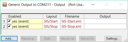
Once Qinsy starts recording the string in the *.xml should be sent out over to the selected port and IP-address, which should result in SIS starting to record simultaneously with Qinsy.
Additional Information
Package loss
Make sure to only select the messages you need (N, Y, C, k datagrams).
We have seen problems where packets were dropped.
Dual head package loss
A 'Balanced' (default) power plan on the HWS can cause package dropouts from the second head. This can be solved by changing the power plan on the HWS pc from 'Balanced' to 'High Performance' when using a Windows7 pc.
Driver is available since Qinsy release version 8.00.04.15.1
Info
As of the December 2011 Qinsy version it is no longer necessary to change anything in the registry, by default the calculated footprints will be fully corrected.
Info
As of March 2013 the Sidescan system support has been removed. The raw seabed data is now part of the multibeam data.
Registry Options
Warning
In previous versions, in order to calculate the beam results properly two registry keys had to be set, as described below:
HKEY_CURRENT_USER\Software\QPS\Qinsy\8.0\Core\MultiBeamer\Settings
First key:
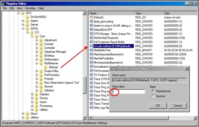
LA calc method [0 OMG(default), 1 QPS, 2 QPS Legacy|0 OMG(default), 1 QPS, 2 QPS Legacy]
This key must be on 1.
Second key:
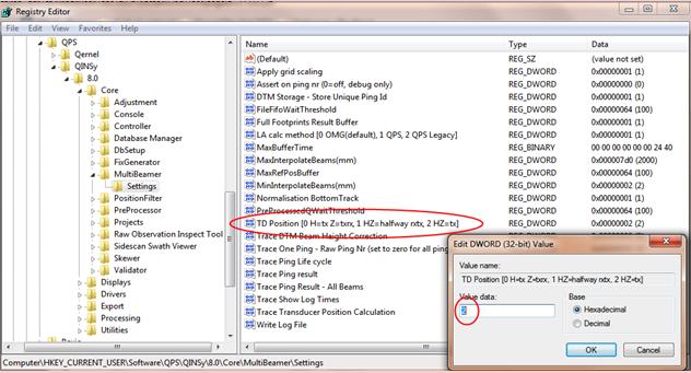
TD Position [0 H=tx Z=txrx, 1 HZ=halfway rxtx, 2 HZ=tx]
This key must be on 2. (default is 0)
Failure to set the keys properly will lead to wrong footprint results.
The port and starboard beams may be reversed then and a height offset may occur.