Description
Driver that decodes bathymetry data, seabed imagery (for raw storage) and water column data from the latest models Kongsberg multibeam echosounders equipped with firmware that supports the new "KMALL" protocol.
For raw data processing the driver can optionally store raw bathymetry and seabed image records in the Qinsy database.
Supported systems, including the MK2 models, that QPS is aware of:
-
EM2040
-
EM2040C
-
EM2040P
-
EM2040M
-
EM2042
-
EM124
-
EM304
-
EM712
Suggestion communication protocol
As of Qinsy 9.7.3 we no longer have a preference for a communication protocol.
-
TCP (preferred by Kongsberg)
-
UDP Multicast
-
UDP
Note that the data is send over multiple ports (multiport, not to be confused with multicast).
Before Qinsy 9.7.3, please use UDP Multicast - Multiport.
Driver Information
|
Driver |
Kongsberg KMALL |
Interface Type |
UDP Multicast/ UDP/ TCP |
Driver Class Type |
|
|---|---|---|---|---|---|
|
Yes |
Input / Output |
Input |
Executable |
DrvQpsFreeBase.exe |
|
|
Related Systems |
|
||||
|
Related Pages |
|||||
Coding Notes
Driver decodes the following datagrams:
Licensing (Kongsberg)
System Setup
This chapter of the documentation talks about the following subjects:
-
Transducer setup and offsets;
-
Kongsberg K-Controller setup;
-
Survey PC/Network setup.
The next chapter explains how to set it up in Qinsy.
Transducer setup and offsets
You can expand the following sections to get more info on some specific sensors that we have.
For the systems that are not mentioned we suggest to measure the Tx and Rx phase center locations.
EM2040
An EM2040 Single Head systems is equipped with one Transmit transducer and one Receive transducer; an EM2040 Dual Head system is equipped with one Transmit transducer and two Receiver transducers.
The RX and TX transducers of the EM2040 can each be oriented normally or reversed. The Heading offset angle should either be around 0° or around 180° when the orientation is reversed.
The Receive (RX) transducer is mounted normally (0°) when the connector points to bow and reversed (180°) when it points to stern. For Transmit (TX) transducer this is port (0°) and starboard (180°) respectively.
It seems that most EM2040 systems in the field have the RX connector pointing to stern and TX connector pointing to port, so the Multibeamer heading offset should be for the TX 0° and RX 180°. However, all combinations are possible.
Note that for the sake of simplicity of usage in Qinsy it is by far the easiest to mount the transducers with normal, non-reversed, orientation.
Note that for a dual head system with reversed RX transducers (heading offset around 180°) the roll offset should be around -30° for port side and +30° for starboard side, this is exactly opposite to what is common with "normal oriented" systems.
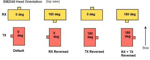
The figure above shows the orientation of the EM2040 Transducers and the approximate Multibeam System Heading offset that needs to be entered in Database Setup.
Reversed Sign
If the RX transducer is reversed, the Roll value as determined in the patch test should have a reversed sign (meaning the transfer option can't be used).
Phase Center offsets (PCO) used by Qinsy are shown below.
|
Device |
Tx PCO (in mm) |
RX PCO (in mm) |
Comment |
|---|---|---|---|
|
EM2040 |
port: -55,0,12 |
0,11,6 |
The 3 TX line array's x,y,z positions are relative to the center of the sonar head face.
Offsets are in millimeters (port-starboard, stern-bow, up-down). Starboard, bow and up are positive. |
|
center: 13,0,6 |
|
||
|
starboard: 55,0,12 |
|
EM2040C
For the EM 2040C, the TX and RX arrays are integrated into a common sonar head. The transducer arrays are not placed at the center of the sonar head.
The EM 2040C can have one or two sonar heads. For most EM echo sounders separate x,y,z installation parameters are given for the RX and the TX arrays.
For EM 2040C the installation parameters entered by the operator refers to the centre of the face of the sonar head(s).
Acknowledgement: Text by Kongsberg EM Series Multibeam echo sounder EM datagram formats, 850-160692/V July 2016 © Kongsberg Maritime AS
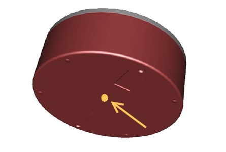
'EM2040C Reference point, the so-called face of the center of the transducer'.
Phase Center offsets (PCO) used by Qinsy are shown below.
|
Device |
Tx PCO (in mm) |
RX PCO (in mm) |
Comment |
|---|---|---|---|
|
EM2040C |
40,3.8,6 |
0,-46,6 |
The coordinates are given in the Vessel Coordinate System, where x is forward, y is starboard and z is downward.
Offsets are in millimeters (port-starboard, stern-bow, up-down). Starboard, bow and up are positive. |
EM2040P
For the EM 2040P, the TX and RX arrays are integrated into a common sonar head. The transducer arrays are not placed at the center of the sonar head.
For most EM echosounders separate x,y,z installation parameters are given for the RX and the TX arrays.
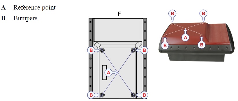
For EM 2040P the installation parameters entered by the operator refer to a reference point on the face of the sonar head. This point is not marked on the sonar head.
The reference point used is the intersection between two diagonal lines drawn between the bumpers on the sonar head face.
Phase Center offsets (PCO) used by Qinsy are shown below.
|
Device |
Tx PCO
|
RX PCO (in mm) |
Comment |
|---|---|---|---|
|
EM2040P |
port:
|
0,204,32 |
The 3 TX line array's x,y,z positions are relative to the center of the sonar head face.
Offsets are in millimeters (port-starboard, stern-bow, up-down). Starboard, bow and up are positive. |
|
|
center:
|
|
|
|
|
starboard:
|
|
Kongsberg K-Controller setup
The following section explains what you need to setup in the Kongsberg K-Controller.
Expand for more info...
The multibeam system can be controlled from Kongsberg's K-Controller utility.
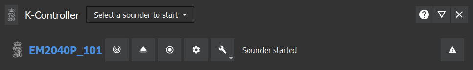
This utility is also used to configure IP addresses and ports used.
UDP vs TCP Setting in SIS
Please note that the following setting within SIS must be set according to the interface type you are using:
Parameter Setup - Logging Control - Use TCP for data from PU. Enabled if 1, disabled if 0
Where if you are working with the UDP or UDP multicast drivers, this value must be set to 0.
UDP Multicast IP
Please note that due to the communication technology used by Kongsberg (UDP multicast), you will need to select an IP address from the multicast range (224.0.0.0 to 239.255.255.255).
Survey PC/Network setup
The following part explains what network/PC settings you might need to check in order to get the MBES data properly into Qinsy.
Expand for more info...
Network cable
Preferably a direct cross-over network cable should be used to transfer the data. This will minimize the chances of any dropped packets.
It is also recommended to have a direct network connection from the Kongsberg PU to a dedicated network card on the survey PC.
Especially when sending a lot of data (water column data for example).
Network switch
In case you don’t have a direct connection of the PU and you are using a switch in combination with the UDP Multicast protocol, we suggest to use a managed network switch.
This ensures that only the systems that request the data, get the information forwarded from the switch.
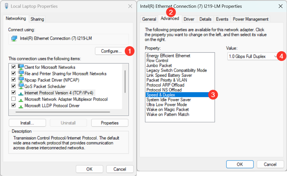
Network card on survey PC
Kongsberg suggests to enable the following setting to ensure that the network card is not automatically changed to a lower setting.
Connection problems or packet loss
In case you are experiencing connection problems, i.e. data not coming into Qinsy, please have a look at the following tips.
Connection loss between K-Controller and Qinsy 9.1.1
Currently Qinsy will only check the network adapter with the highest priority because the communication technology used is UDP multicast.
It is advised to change network priorities when there are multiple network adapters available to ensure that the network adapter connected to the PU has the highest priority.
To change priority of a network adapter use the following steps:
-
Go to the Network Connections view
-
Go to the Properties of the network adapter you want to prioritize
-
Open up the Properties of Internet Protocol Version 4 (TCP/IPv4)
-
Click the Advanced button
-
Uncheck the 'Automatic metric' and assign a priority value for the adapter
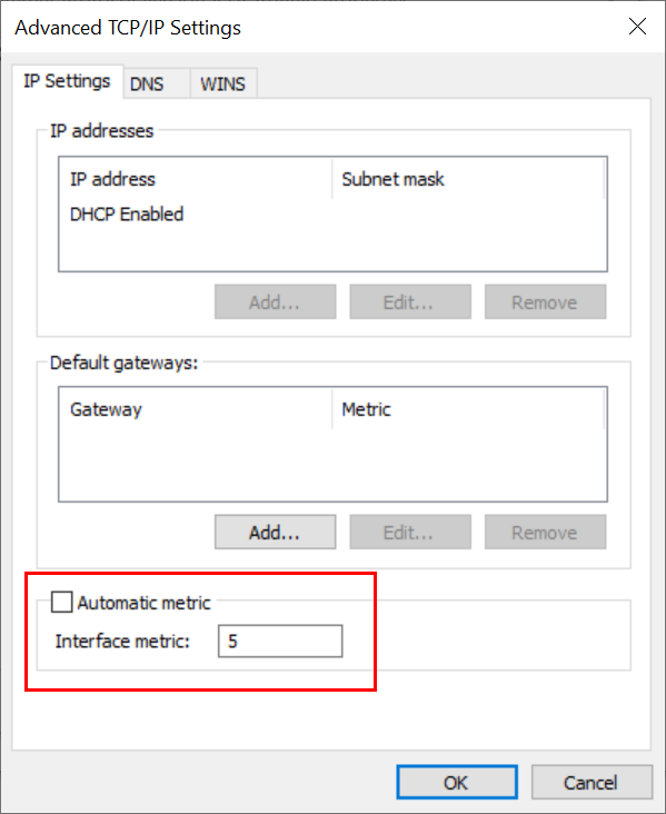
A lower 'Interface metric' number means higher priority.
Packet loss
A 'Balanced' (default) power plan on the PC can cause package dropouts from the second head.
This can be solved by changing the power plan on the PC from 'Balanced' to 'High Performance' when using a Windows 10 or Windows 11 pc.
Qinsy Configuration
Multibeam Ecousounder
Below an example of how to setup the UDP Multicast driver.
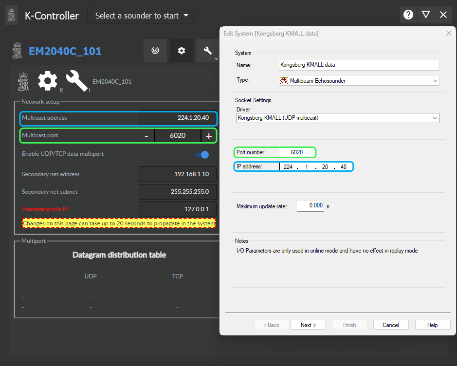
Set the Port number and IP address to same as set in the Kongsberg K-Controller.
Make sure that the port number is the same in Database Setup and in the K-controller/SIS-5.
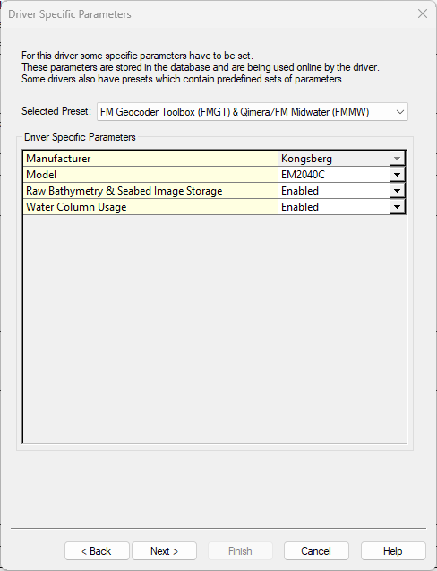
If you disable everything, the Qinsy driver will decode the Bathymetry footprints (Angles and two way travel time) and the Intensity average per beam.
If you would like to process backscatter (Seabed Imagery) or water column later on, you can select the following presets.
|
Selected preset |
Raw Bathymetry Storage |
Raw Seabed Image Storage |
Water Column Usage |
|---|---|---|---|
|
FM Geocoder Toolbox (FMGT) |
|
|
|
|
FM Midwater (FMMW) |
|
|
|
|
FM Geocoder Toolbox (FMGT & FM Midwater (FMMW) |
|
|
|
|
XTF Export |
|
|
|
The model selection only has effect on the next page were you enter the offsets and Patch test values.
More info can be found on the following page:
|
System |
Suggested Transducer setup |
Additional info |
|---|---|---|
|
EM 124 |
Seperate transmit (Tx) and Receive (Rx) elements |
|
|
EM 304 |
Seperate transmit (Tx) and Receive (Rx) elements |
|
|
EM 712 |
Seperate transmit (Tx) and Receive (Rx) elements |
|
|
EM 2040 |
Seperate transmit (Tx) and Receive (Rx) elements |
|
|
EM 2040-C |
Transducer reference point |
|
|
EM 2040-P |
Transducer reference point |
|
|
EM 2040-M |
Transducer reference point |
|
|
EM 2042 |
Seperate transmit (Tx) and Receive (Rx) elements |
Please note that the TX is reversed on both the Kongsberg and Universal Sonar Mount portable mounting frames. As a result, it is necessary to apply a TX transducer yaw offset of 180°. |
|
Other |
Seperate transmit (Tx) and Receive (Rx) elements |
Select this if your model is not part of the list or if you do not want to use the “Transducer reference point”. |
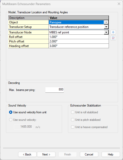
On this page you can select the right node offsets. This is either the reference position or the location for the Rx and Tx element.
|
Roll/Pitch/Heading offset |
Patch Test values.
|
|---|---|
|
Max. Beams per ping |
Set this to the maximum amount of footprints per ping (per head). |
|
Sound Velocity |
We always decode the sound velocity from the unit (measured near the head). |
|
Echosounder Stabilization |
Not applicable. |
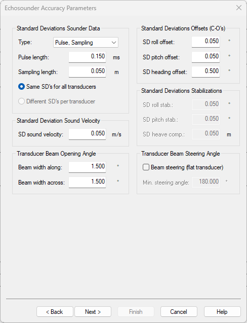
These settings are used for the TPU calculations. For more info, press F1.
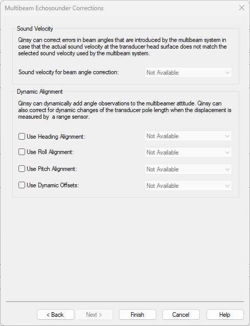
No need to enter anything on this page.
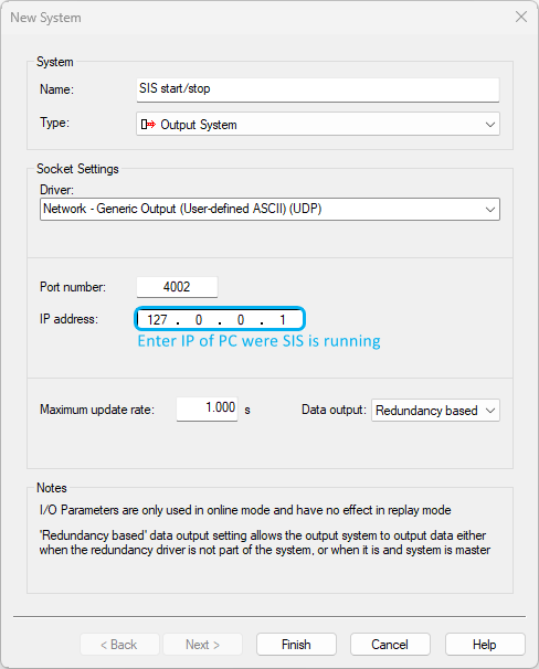
Output System
An output system can be add to let SIS-5 start/stop logging at the same time as Qinsy.
Click here to expand...
Difference SIS5 vs K-Controller
It is important that logging can only be started if SIS5 is running together with the K-Controller:
-
In SIS-5 you can remotely Start/Stop both Pinging and Logging.
-
In the K-Controller you can remotely Start/Stop Pinging only.
Add the XML files in the table below to this location:
-
C:\Users\Public\Documents\QPS\Qinsy\Drivers\Definitions\Output
|
XML files |
||
|---|---|---|
|
System |
Start command |
Stop command |
|
EM2040 |
||
|
EM2040C |
||
|
EM2040P/EM2040M* |
||
|
EM2042 |
||
|
EM712 |
||
|
EM304 |
||
|
EM124 |
||
*Prior to SIS Release 5.10.0, the XML for EM2040P/M was the same as that of the EM2040.
Downloading the XML files
The xml-files above are only visible when logged in to the QPS website, not when viewing the Drivers Manual from the Qinsy Console.
Logging data with Qinsy and SIS on the same PC
QPS advises to run SIS and Qinsy on separate PC's to allow both systems to run on maximum performance.
When logging data with both packages on one PC, this can lead to storage issues due to the large amounts of data.
Additional info
Click here for more info...
Frequently asked question regarding upgrading to us the K-Controller (KMALL format)
Coming from an old setup (either using SIS as controller or using the EM Controller in Qinsy) the following needs to be considered:
-
Changes in cabling: User can rewire the SV sensor to the processing unit directly.
-
Entering geometry in the K-Controller: For a Qinsy setup it is not necessary to enter the full geometry. However, for Kongsberg support purposes it could be useful.
There is the option of logging in KMall format in the K-Controller, and Kongsberg prefers that when supporting with problems. Problem finding is made easier if the offsets are correct. -
How to use the K-Controller: Kongsberg has a reference manual available: 'K-Controller Installation and runtime controller for EM multibeam echo sounders'.
-
It is no longer possible to use the EM-controller in Qinsy with the new format. It is not possible to change settings from Qinsy.
-
Which Kongsberg multibeam models are supported: Beginning 2019 the EM 2040P is supported with EM2040C; EM2040 and EM712 expected later during the year.
-
Qinsy databases will be larger in size. More data is being sent and stored when raw data logging is on.
Compatibility
Please note that, due to a non-backwards compatible change in the protocol, systems that use the 'REV-I' or newer version of the protocol will only work with Qinsy 9.4.3 and later.
You can find out which protocol your system is using by looking at the software release notes as installed with the K-Controller/SIS: