
On this page:
To learn more about the inner workings of the Volume Calculation, please refer to How The Volume Calculation Works in the Help pages.
To learn more about terminology used, refer to Volume Results Terminology.
Visualize Layer Differences

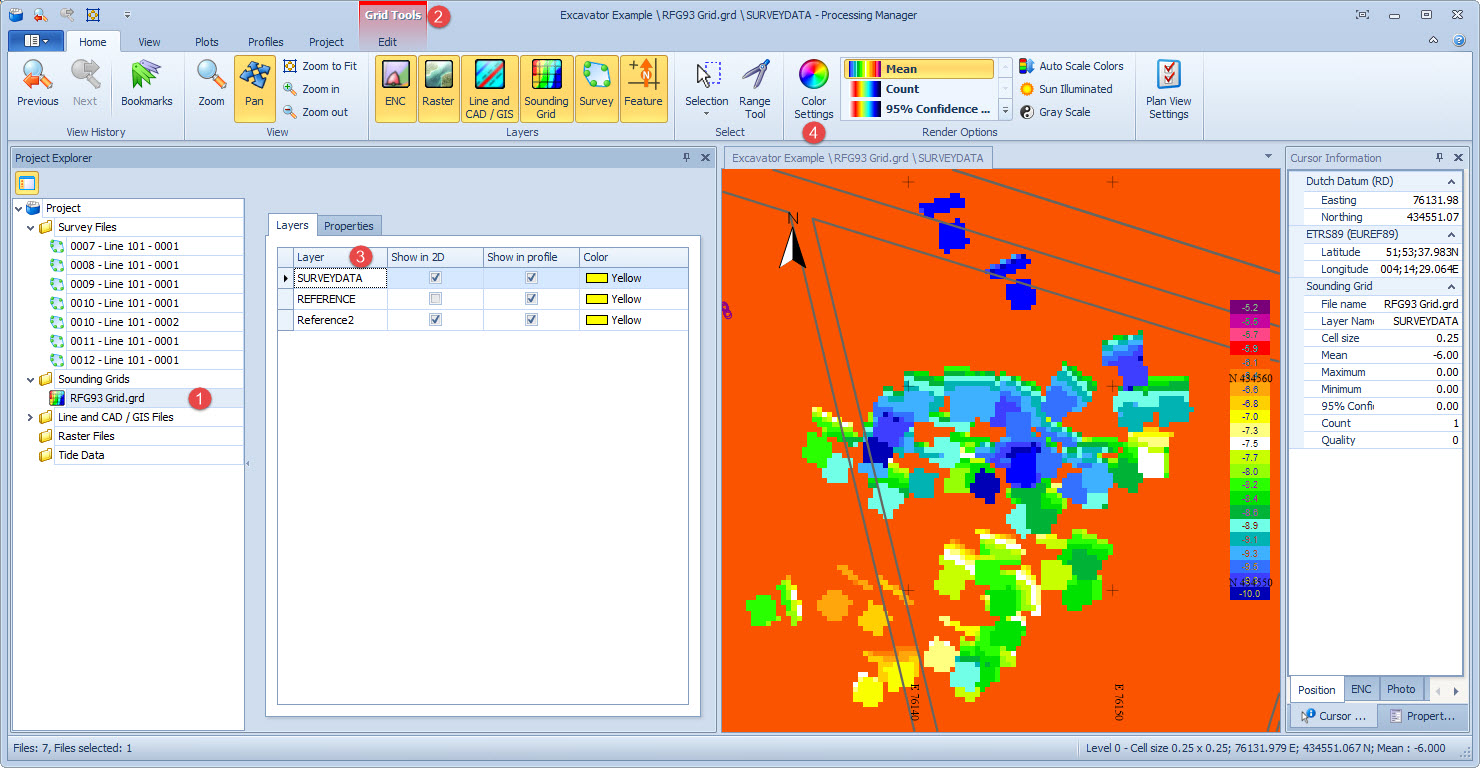


Hiding or showing individual layers is done in the Project Explorer pane by ticking the check boxes in the 2D column (shown in the image above)..


-
To be dredged PAID
-
Total
-
Min
-
Design
-
Max
-
-
To be done
-
-
Dredged NOT paid
This requires you to:
-
Compute volume between the in-survey layer and the design layer.
-
Compute volume between an interim dredged layer and the design layer.
-
Compute volume between the final dredged layer and the design layer.
-
Compute volume between the final dredged layer and the design layer.
-
Compute volumes for all the above but using the upper and lower tolerances.

Usually volumes are computed using the attribute 'Mean'.
|
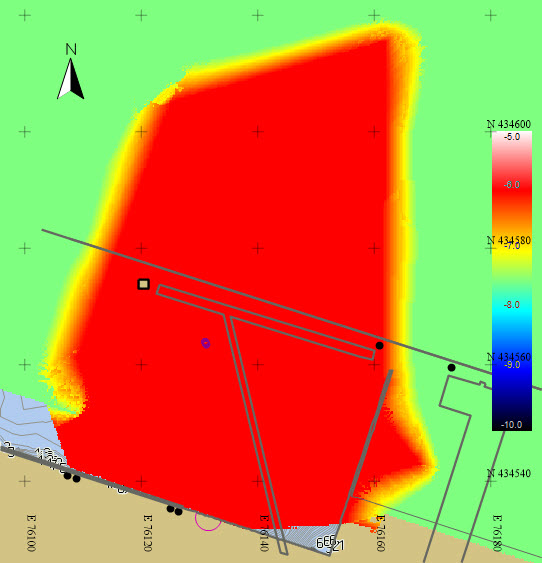
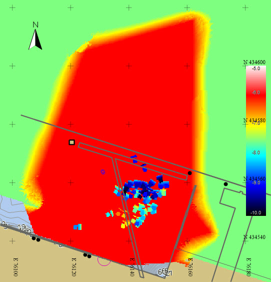
Insurvey bathymetry layer (Max = -5.0, Min = -10.0) |
Design bathymetry layer (Max = -5.0, Min = -10.0) |
|
Dredged bathymetry layer (Max = -5.0, Min = -10.0) |
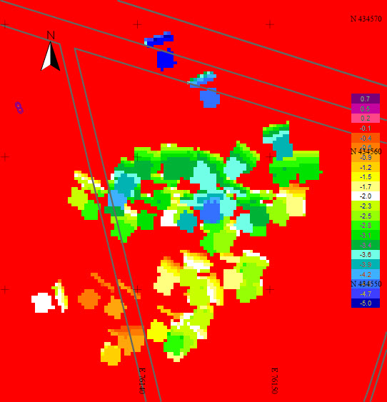
Difference between Insurvey and Dredged bathymetry layers
|
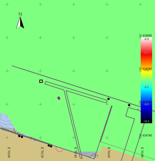
So far only a visualization of the dredging results has been presented. The next step is to produce volumes.
Return to: top of page.
Calculation Procedure

Be patient as it can take quite some time to open!
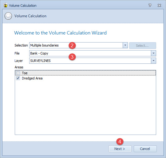
Here select the area(s) to use as boundaries to the volume calculation.

The latter refers to the area defined using the Selection button in the Home ribbon tab.
When set to Current Selection the extents defined using the Selection button are used.
When no selection is made, or when a different selection is needed, click on the 
The Wizard is then hidden until a valid selection is made with the Selection tool.

Then choose the layer and polygon(s) to use. Any checked areas are used for the volume calculation. Use Ctrl+A to select all areas listed.

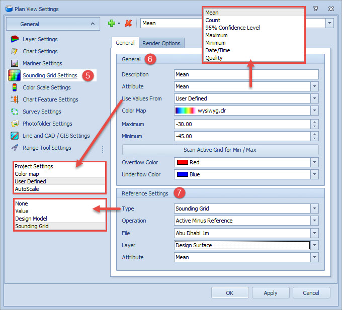
Choose the active and reference layers to use in the volume calculation based on the differences between these two layers.
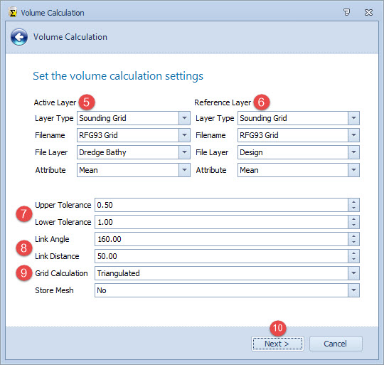
The selection is used for the Active Layer in the volume calculation.
This allows you to specify a single depth to use in the volume calculation.

These are used to optimize the TIN (Triangulated Irregular Network) models used for the Volume Calculation.
Typically a link angle of 160 degrees is used. Link distance depends on spacing of depth points.

Square columns method
|
The square columns method enumerates over all sounding grid cells in the area of interest. For each cell the necessary attribute (mean, deepest or shallowest) is read. At the same location one sample is taken on the reference layer.
In the case that a grid cell is partially in the area of interest, the exact area within the area of interest is calculated and used. The square columns method is a fast and memory friendly approach. |
Triangulated method
|
For the triangulated method, both the active and reference layers are triangulated. The resulting triangulated layers are then compared to calculate the volumes.
For a full explanation, also refer to How the volume calculation works. |

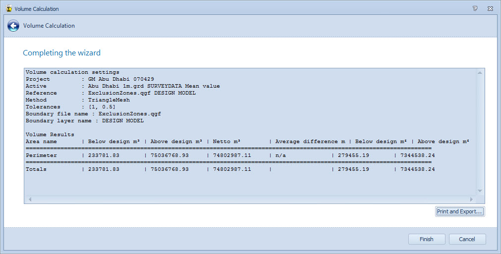
On completion results are displayed in the final page of the wizard.
A summary of the volume calculation is shown below.

Return to: top of page.
Volume Calculation Report
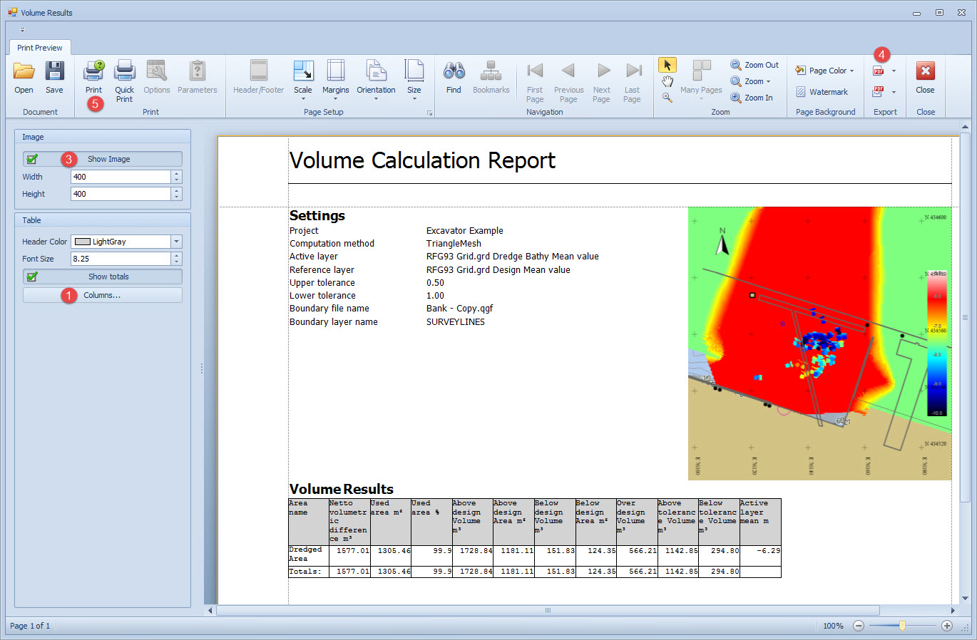
Most of the parameters on the Volume Results page relate to configuring the report and are self-explanatory.
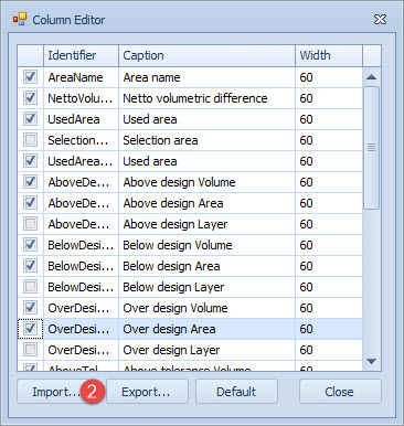
Use the Import button to import an existing configuration file. Files are stored in the \Export folder.
Various formats are available:
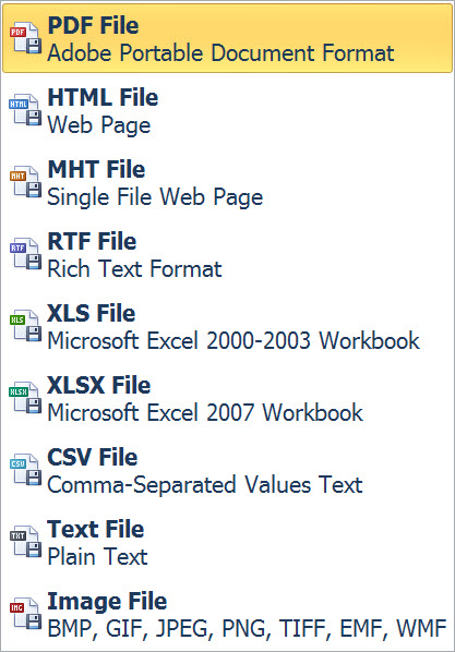
Return to: Quickstart - BHD.