
Session Setup
|
|
|
|
|
Refer to BHD - Session Settings for a more detailed explanation.
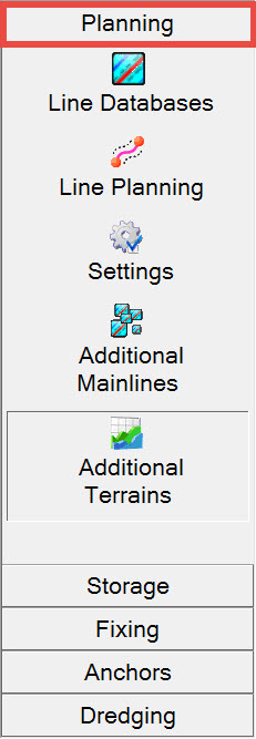
Planning


Add all line files to use as survey lines to be sailed, and also any line files to use in the Navigation Display for visualization/context purposes, e.g. exclusion zones, no go areas.
Within each line database, enable the points, lines and polylines (routes) required to be active.


Return to: top of page.
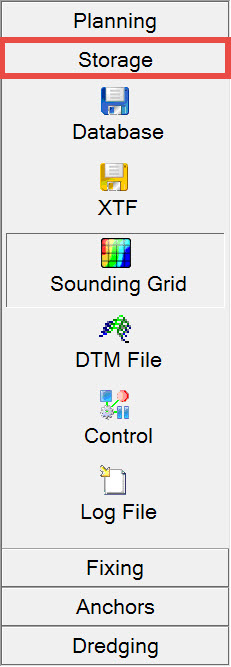
Storage


Allow time for the actual creation process to complete. Also check the task bar for a minimized Create Sounding Grid window.
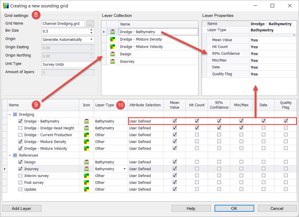

If the minimum cell size is entered as 1x1 m, the following grid levels are automatically generated: 2x2 (level 1), 4x4 (Level 2), 8x8 (Level 3), 16x16 (Level 4) and 64x64 (Level 5) as an overview level.

Note that checked layers are reflected in the Layer Collection pane.

Each predefined Attribute Selection causes certain boxes to be checked. User Defined leaves the decision up to you.
Click OK to complete the creation.

Choose between:
-
Age - When the last update in a cell exceeds a certain age the cell is cleared and filled with newer data.
-
Used for example when a BHD track overlays a previous track. The data is averaged if the data is not older than the threshold age set.
-
Also useful if you want to redo a survey line and only want to overwrite the sounding grid data of the previous attempt.
-
-
Time (older than)- When the data in a cell is older than the Time and Date entered by the user, the cell will be cleared and filled with new data.
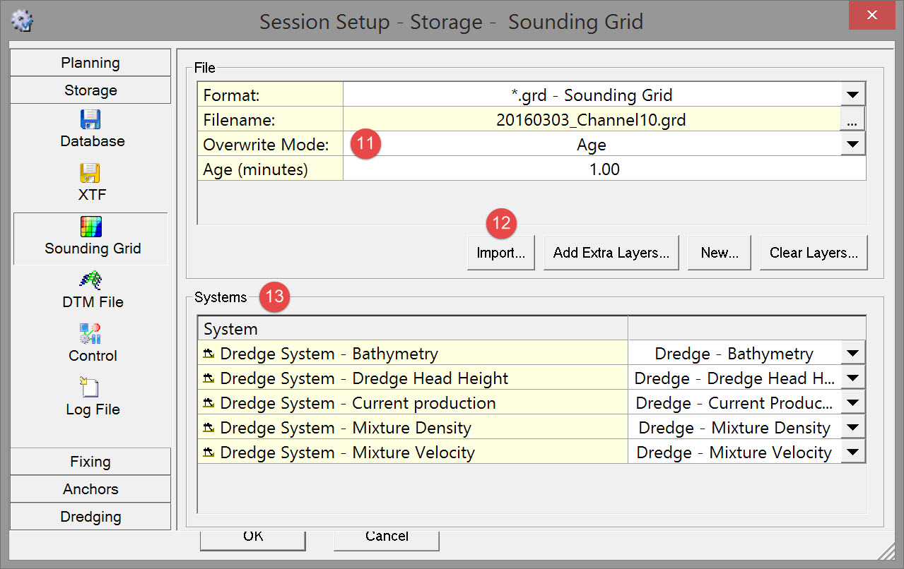

This could be, for example, data for a design surface, in-survey, interim survey, etc..


Choose one of the storage format options:
Choose a file naming mode:

Choose a Flagged FP (footprint) mode:
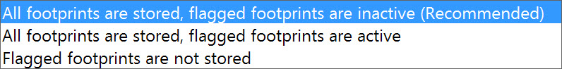
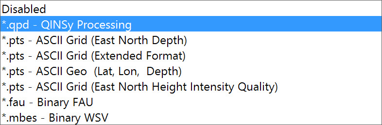
If you chose format *.qpd - QINSy Processing this extra line appears where you can select from three options:
-
All footprints are stored, flagged footprints are inactive (Recommended) - The most commonly used option. Data that did not pass the online filters has been flagged, but not deleted. So during processing the flagged data can be easily restored if needed.
-
All footprints are stored, all footprints are active - Normal, full QPD.
-
Flagged footprints are not stored - Reduced QPD. The file is of the same QPD format as both options above, but does not contain footprints that have been flagged by the online filters. The main benefit is the smaller file size of the *.qpd files.
However, if you need to restore flagged data you will need to completely replay the database and create a new *.qpd file with different online filter settings.
Note: This format is not available when replaying recorded databases in batch in combination with the file Mode set to User-defined name, due to the fact that *.qpd files cannot be appended to.
Control

Choose whether to split Storage Database Files, and, if so, select which option.
Choose whether to use Automatic Line Selection, and, if so, select which option.
Choose whether to use Automatic Recording, and, if so, select which option.

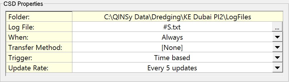
The Output system driver must be Generic Output (User-defined ASCII).
The format of the output file is defined in an XML file made with the Generic Layout Editor.
All logging XML files are listed in the dialog. Check the one(s) to use.
Various logfile properties may be modified in this dialog without actually opening the Generic Layout Editor:
Return to: top of page.
Return to: QS BHD - Session Setup
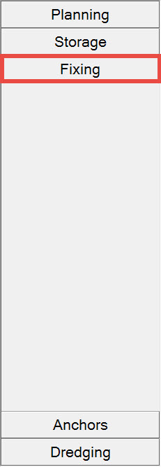
Fixing

Fixes are generated internally based on a number of user-defined properties, or externally through receipt of closures or TTL pulses.
Fixes are stored in the database with the exact time of fix.
Before fixing can be used, a number of parameters need to be set.
First choose the Event (fixing) mode:
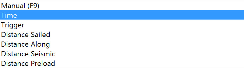
Then enter parameter values that control the fix interval and fix numbering.
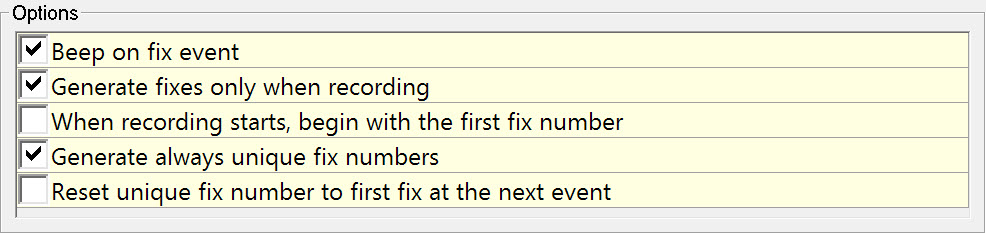
Finally choose fixing options:
Return to: top of page.
Return to QS BHD - Session Setup
Dredging

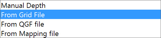
Select the Design Method and specify the source file and layer representing the design DTM when the method is other than Manual Depth:
For design methods From Grid File or From Mapping File enable Use Clipping Depth, if applicable
This option is only available when From Grid File or From Mapping File is selected as Design Method.
This option generates a new target depth for the design. The Clipping Depth that is entered must be an absolute value.
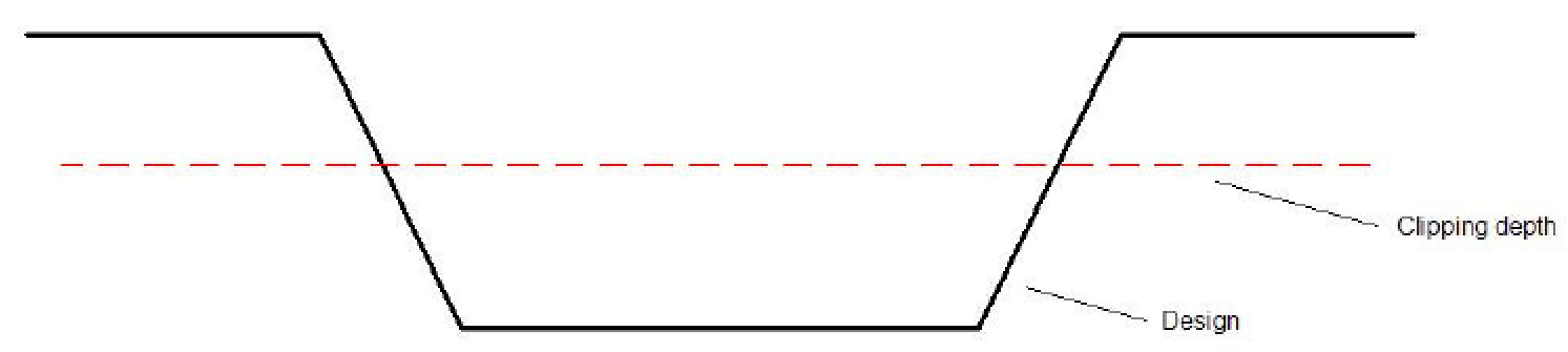
Clipping Depth is used when removal of material is done in layers. The design is clipped to the depth entered and the dredger uses it to control cut depth for that pass. For the next pass the Clipping Depth is set deeper.
Enter Under and Over Dredge Tolerances which are used in volume calculations.

This functionality requires definition of areas ('2D - XY Position' height mode for 2D alarms) and/or three dimensional polylines ('3D - XYZ Position for 3D alarms).
Areas and polylines are created using the line tools in the Processing Manager or the Line Database Manager program.
If the distance between the dredging tool and a 'no go' area becomes less than the Clearance Warning distance, an alarm is raised.
If the distance between the dredging tool and a 'no go' area becomes less than the Clearance Error distance, an Emergency Hoist Alarm is generated and sent to the dredger's PLC.
Note that it is also possible to employ this detection system to protect other dynamic objects in the vicinity of the dredging tool. The hull (areal extent) of an object defined in the template database acts as an avoidance area in much the same way as an avoidance area defined by a polyline, e.g. to prevent a backhoe from hitting a barge/scow.
Select the source file and layer and enter Horizontal and Vertical Clearance distances.

-
Enter a density value for the solids in dry condition. The Density Solid can only be changed under Dumping - Material Type.
-
Enter a density for the water (fresh or salt water). This option is only available when a density table is entered in the template database.
-
Enter a density value for when the solids are settled at the seabed after they have been dumped (this will affect the dump shape that is drawn in the sounding grid). This option is only available when a density table is entered in DbSetup.
-
Enter a production value in cubic meters / second.
-
Count the times that the Poor Mixture Overboard valve is used when the dredge head is in between a tolerance depth and the design depth. The tolerance that needs to be specified lies above the design.
Select the Trip Volume method to use:
-
-
Manual - Total Value - This volume will be used to update the sounding grid when the dumping is done and will overrule the production that was calculated during the dredging operation.
-
Manual - Per Bay - This volume will be used to update the sounding grid when the dumping is done when dump bays are used. Typically this is used for side stone dumpers.
-
Automatic - This will use the production that was calculated during the dredging operation.
-

These influence the dumping process and production values, including updating of the sounding grid to reflect the dump.
For the Material:
-
Choose the Material Type which is discharged. New materials can be added to the drop down list by selecting the New button below the dialog.
-
Drag Along and Drag Across Coefficients are used in determining the dynamic settling location of the dump. Set to 1 if unknown.
-
Absolute In Situ Density and Absolute Solid Density are determined empirically in a laboratory.
For Dumping:
-
-
For the Load Discharge Setup choose By Time or By Rate. Rate must be a known value.
-
Select whether the Current Measurement is done with an instrument such as a DVL (as entered in Database Setup) or entered manually.
-
-
-
For Current Reference select either
-
Relative (Located on Vessel) - the measurement is done on the vessel and corrected for vessel movement.
Absolute (Located Remotely) - the measurement is done in a fixed location.
-
-

This value is subtracted from the dredged depth in the Sounding Grid.
For example: The dredge head is dredging at a depth of 15 meters, but there is a spill of 0.25 meters of material that isn’t removed by the dredger.
The Sounding Grid will store a depth of 14.75 meters.
Proceed to: QS BHD - Primary Displays.
Return to: top of page.
Return to: QS BHD - Online.
Return to: Quickstart - BHD.