
QPS Splitter Box MK 2
This document describes how to use the QPS Splitter Box MK 2.
If you need to transmit Pulse Per Second (PPS) time stamps to various devices at the same time, the Splitter Box can be used.
It has room for one input signal and can output it five times, either converted to QINSy format or directly on coax exits.
Overview of the unit:
Dimensions
|
Height |
2U (4 holes) |
|
Width |
19" (inch) |
|
Depth |
280 mm (housing only) |
Front
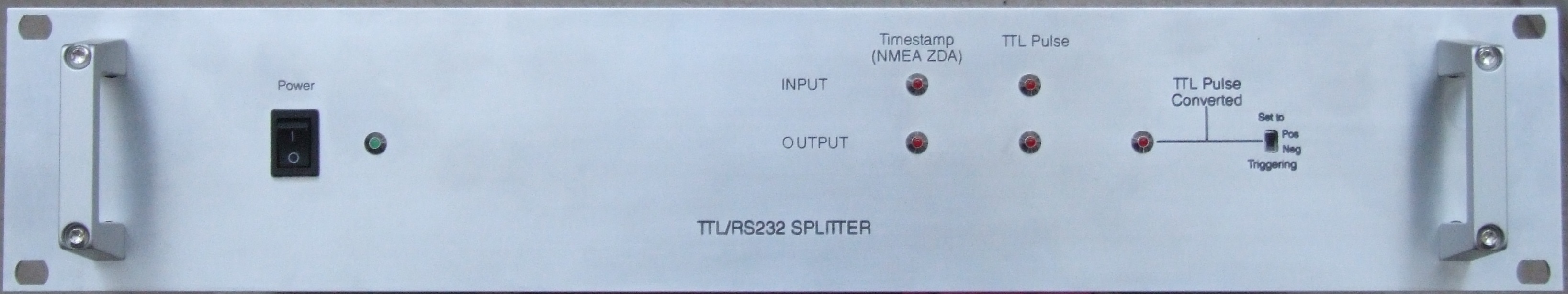
Front panel, from left to right:
Rear
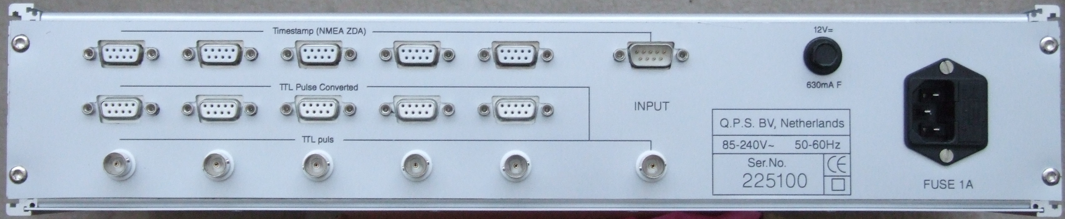
Rear panel, from left to right:
Input
Set of Input Connectors, from top to bottom:
-
Time stamp (NMEA ZDA)
-
TTL Pulse
Output
The output contains 3 sets of output connectors (from top to bottom):
-
Timestamp (NMEA ZDA or Trimble UTC)
-
TTL Pulse Converted (QPS PPS/Fix Adapter) to QINSy
-
TTL Pulse to other devices
Power
-
12VDC Fuse holder
-
Mains Supply with Fuse holder
QPS TTL /RS232 Splitter Device
This unit, which is built as a 19" rack unit, can split RS232 and TLL Data in a fast and safe way.
Data is then available on 5 (galvanically separated) Output ports.
It is powered individually with an internal Power Supply with a Mains Voltage ranging from 85 to 240 Volts AC.
An RS232 signal is transmitted 1-on-1 to the Output ports.
FIX pulses are transmitted 1-on-1 to the 'TTL pulse' Ouputs and to the 'TTL Pulse Converted' Outputs.
De 'TTL Pulse Converted' Outputs are equipped with the same logic as the separately available QPS PPS/Fix Adapter.
Timestamp
The 'Male' D-Sub Input connector is meant for the Time stamp message (NMEA ZDA / Trimble UTC) or any other RS232 signals with a speed of up to 115 kB.
Multiple NMEA messages can be send to the input port i.e.: ZDA + GGA + GST + VTG + UTC, which all will be available on the NMEA output ports.
The signals will be transmitted 1-on-1 and are not inverted.
The 'Timestamp' LEDs on the front panel will indicate activity.
TTL Pulse
The 'BNC' Input connector supplies the incoming signal 1-on-1 to the the 5 other 'BNC' connectors.
The LEDs 'TTL pulse' on the front panel will show this activity.
At the same time the input 'BNC' connector activates the electronics behind the 5 'female' D-Sub connectors, which will output same output as the QPS PPS/Fix Adapter.
This output should be connected with a straight serial cable (Male - Female) to a COM port of a QINSy PC. You will be able to feed up to 5 individual QINSy PC's with a QINSy converted PPS / Fix signal.
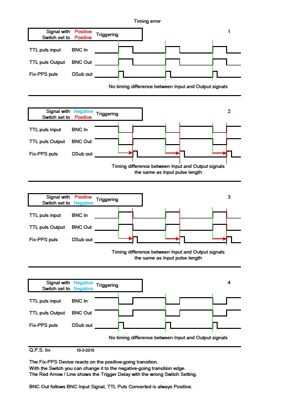
TTL Pulse Converted, Set to Pos Neg Activation
To prevent time delay at negative logics these 5 'Converted' signals are equipped with the possibility to start both on the Positive as well as on the Negative flank.
The entered setting is the same for all 5. The switch 'Set to Pos Neg Triggering' is situated on the front panel.
The LED 'TTL Pulse Converted' shows whether this was set correctly.
It should flash at the same time as the 'TTL Pulse' LED.
Should the 'TTL Pulse Converted' flash after the 'TTL Pulse' LED then it is sufficient to use the switch 'Set to Pos Neg Triggering' to sychronize both signals.
The table below illustrates which timing error will occur when the switch 'Set to Pos Neg Triggering' is set in the wrong position:
Technical Data
Mains Power: 85-240V AC, fuse 1Amp.
Fuse: 12V DC 630mA Fast.
Input signals
-
Male D-Sub conn.: RS232, Timestamp (NMEA ZDA / Trimble UTC)
As from SN 225112 onward PIN 2 (Rx) and PIN 5 (GRD)
Before SN 225112 PIN 3 and 5
-
BNC conn.: TTL signal (Max 6 Volts DC) (Pulse per Second)
Output signals
-
5 Female D-Sub conn.: RS232 out
-
Output on PIN 2 and 5
-
-
5 Female D-Sub conn.: TTL Pulse Converted out
-
Output on PIN 2 and 5
-
-
5 BNC conn.: TTL pulse equals input pulse
Unit must be connected through power cord to Earth or Ground.
Maximum Input & Output cable length: <3mtr or <10’.