
This document aims to explain how to work with Ultra Short BaseLine (USBL) systems within our software and where to find useful related information.
What is a USBL?
The following page gives you additional theoretical information about USBL systems:
How to calibrate a USBL?
Click to expand...
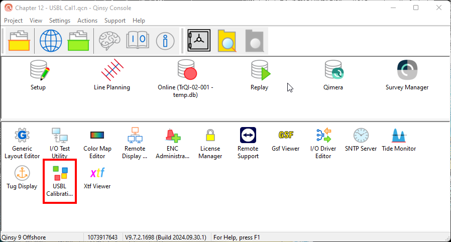
This is usually done in the USBL software and we would normally direct our customers to the manufacturer's documentation. We also have a tool in Qinsy to calibrate a USBL called the USBL Calibration Utility.
The tool can be found in the Qinsy Console:
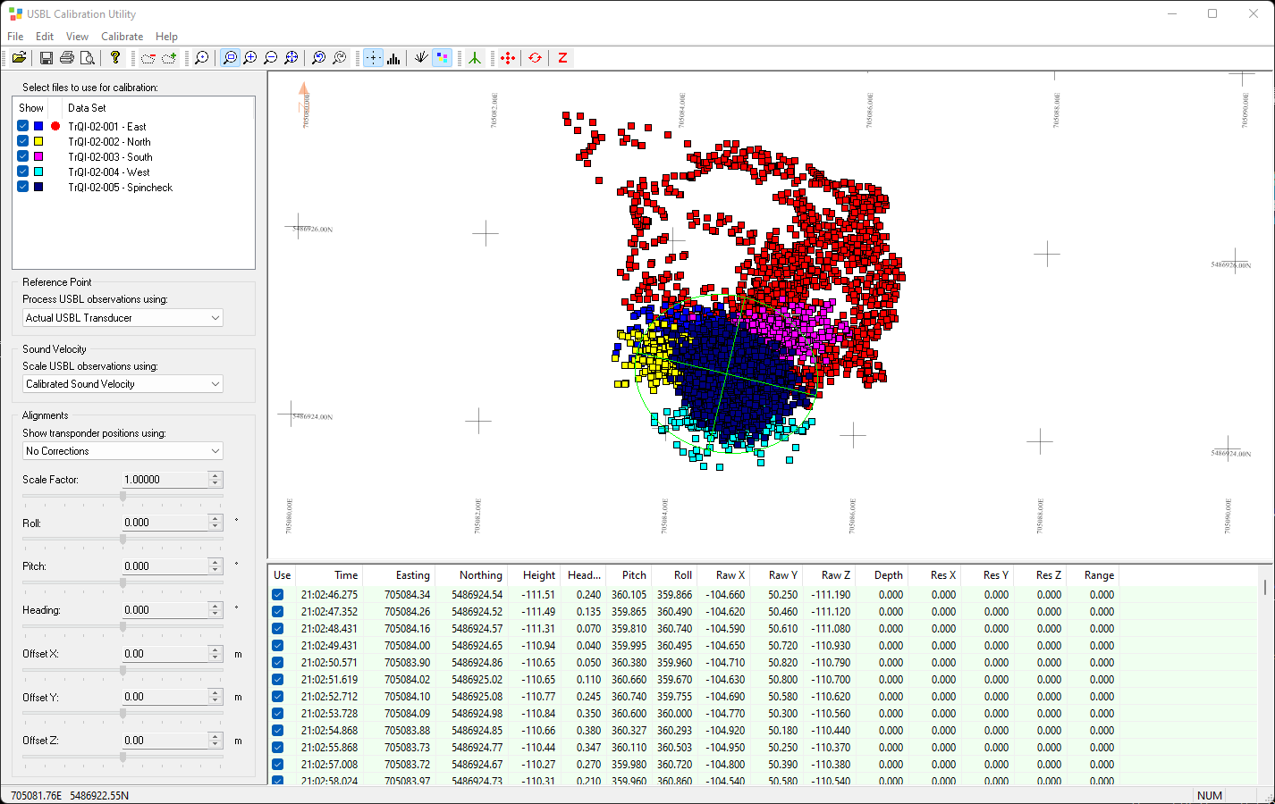
The How-to on how the tool works can be found here:
How to interface a USBL in Qinsy?
Click to expand...
Supported systems
We have created an overview of some of the frequently used systems that are interfaced with Qinsy. Note that we are actively adding manufactures/systems so if you want us to add one, just let us know.
The Equipment Space can be found via the following link:
Your system may not be on this list. However, the format that it outputs (see below) might very well be supported.
Supported formats
Qinsy supports several USBL formats. These can be found on the following page:
In case it is not in that list, you can also create your own driver. This is possible, if it is ASCII and send over Serial or UDP connections. The following How-to explains how this works:
What is decoded?
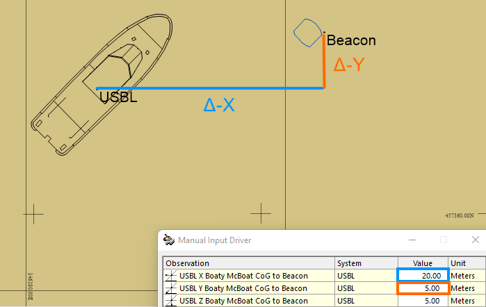
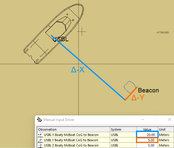
Qinsy decodes a Δ-X, Δ-Y and Δ-Z (Δ= delta).
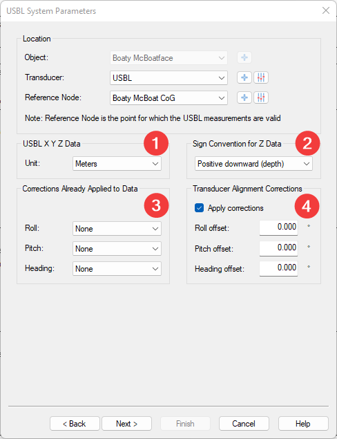
Depending on the system you are using and how it is set up, you will need to tell Qinsy, how to interpret these values. In the setup, there are 4 groups of settings:
Info on this can be found in the Help pages (press F1 when you have this dialog open).
-
Or click this link: DbSetup File System USBLSystem (does not work if you click this on the website).
Item 3 is also explained there, but below is a simple overview of what happens if you set Heading to None.
This means that the USBL is not corrected for an external Heading observation.
So it is then interpreted as Δ Easting, Δ Northing and Δ Height relative to the Transducer location in the World frame (North-up).
You could also set it to Corrected Gyro, meaning USBL is receiving a Vessel Heading and correcting for it.
Then it is interpreted as Δ-X, Δ-Y and Δ-Z relative to the Transducer location in Vessel frame (Bow-up).
Since this is a 3D calculation, you also need to take Pitch and Roll into account. This since Δ-X, Δ-Y and Δ-Z could already be compensated if Pitch & Roll data is interfaced to the USBL. Then you don’t need to apply it again in Qinsy.
Again, for more info, please read the Help page.
What is not decoded?
We do not decode the raw (slant) ranges from the USBL and used Sound Velocity near the head.
So in other words, we do not ray-trace the beacon location, like we do with MBES.
This means you will need to load the Sound Velocity Profile (SVP), into the USBL software as that takes care of ray-tracing.
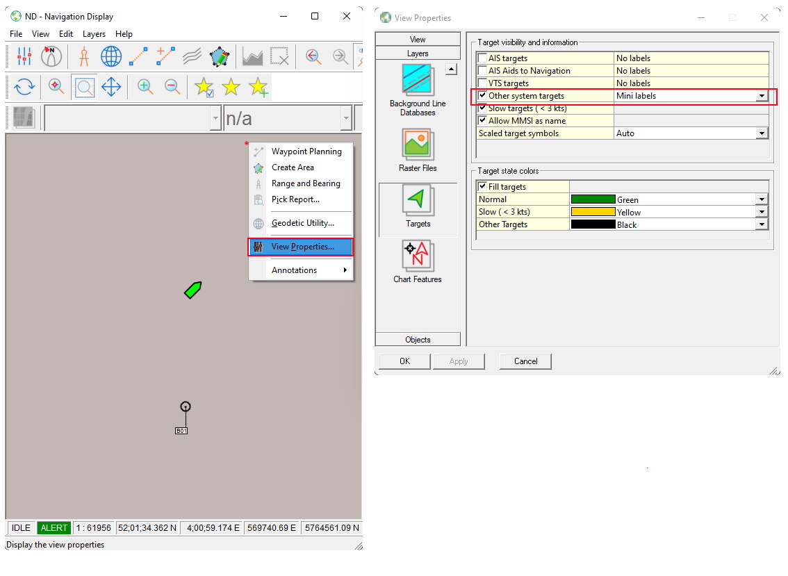
ARPA targets
It is also possible to decode the USBL beacon location as an ARPA target.
This allows you to show a rough location of the beacon in the water, including a label with the beacon ID, in the Navigation Display as a sanity check.
How to use a USBL Online (Computation)?
Click to expand...
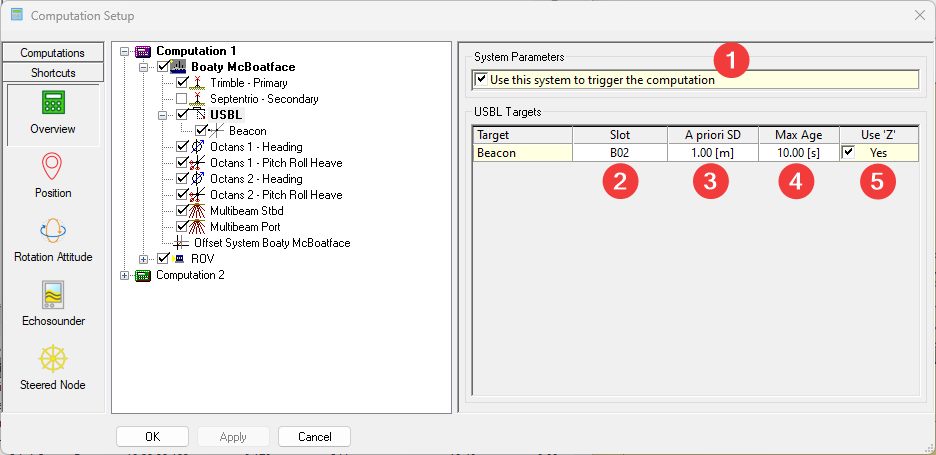
There are several settings in the Computation setup:
-
Trigger;
More info on the can be found here: How-to Computation Trigger. -
Slot;
This is your Beacon ID. This could change if you swap beacons for example. -
A priori SD;
-
This will have effect on how Qinsy calculates the object (ROV) in case there are multiple observations on the ROV (multiple beacons for example). More technical info can be found here:
How-to Computation Setup -
Additionally, it will have effect on the TPU. More info can be found here:
How-to Total Propagated Uncertainty - TPU
-
-
Max Age;
Once this value is exceeded, the USBL observation will no longer be used for computing the object (ROV). -
Use Z.
When enabled, the Z value of the USBL is used. Since this is often not very accurate, especially when the Beacon is far away horizontally, users might want to use a Depth sensor. If you disable Use Z and enable a Depth sensor, the Z of the USBL is ignored and the Depth sensor will be used to determine the height of the ROV.
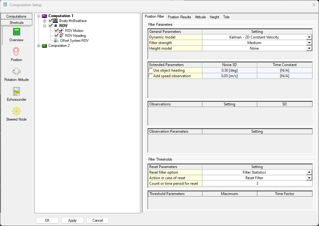
Kalman filter (real-time)
Additionally, it is possible to improve the ROV position further (real-time) by using a Kalman filter on the ROV object position (positioned by USBL).
-
More info can be found in the following document: How-to Smooth Vessel or ROV Track
What can you visualize in Qinsy Online?
Click to expand...
Navigation display
You can show the ARPA targets.
Generic display
This display allows you to display textual information.
The following page shows you what you can display: