Exporting Seismic - SPS (Shell Processing Support) Format
On this page:
Info
Please refer to http://www.seg.org/resources/publications/misc/technical-standards for a description of the SPS Format.
SPS Purpose
Shell Processing Support (SPS) data format was initially defined and used by Shell Internationale Petroleum for transferring of positioning and geophysical support data from 3D field crews to seismic processing centers.
In 1993 SEG Technical standards committee on ancillary data formats adopted SPS as the standard format for exchanging Geophysical positioning data.
Info
Qinsy exports positioning data records only for objects defined in the template database as Gun Arrays.
Both a *.DB and *.RES file are required for successful export.
Qinsy Export Wizard
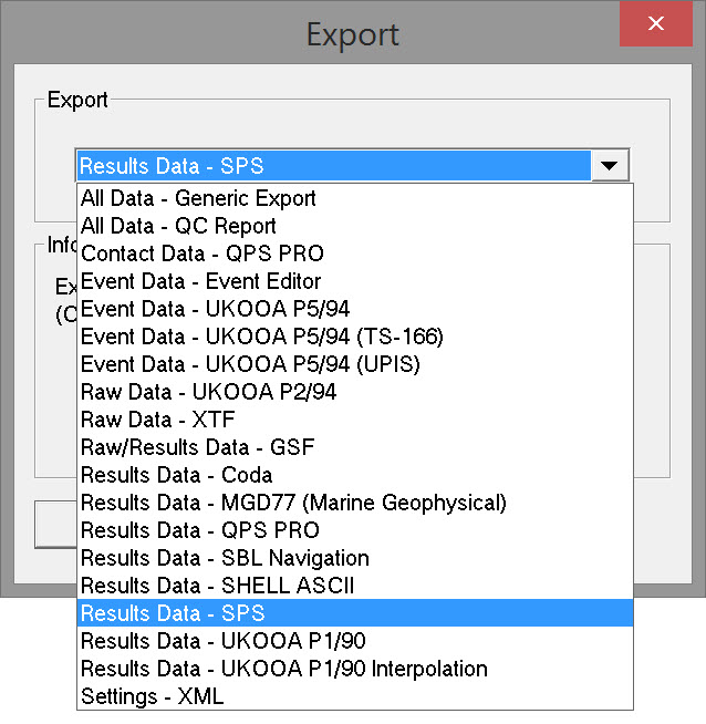
Select 'Results Data - SPS' and click OK to open the export wizard.
Page 1 - Export Results to File
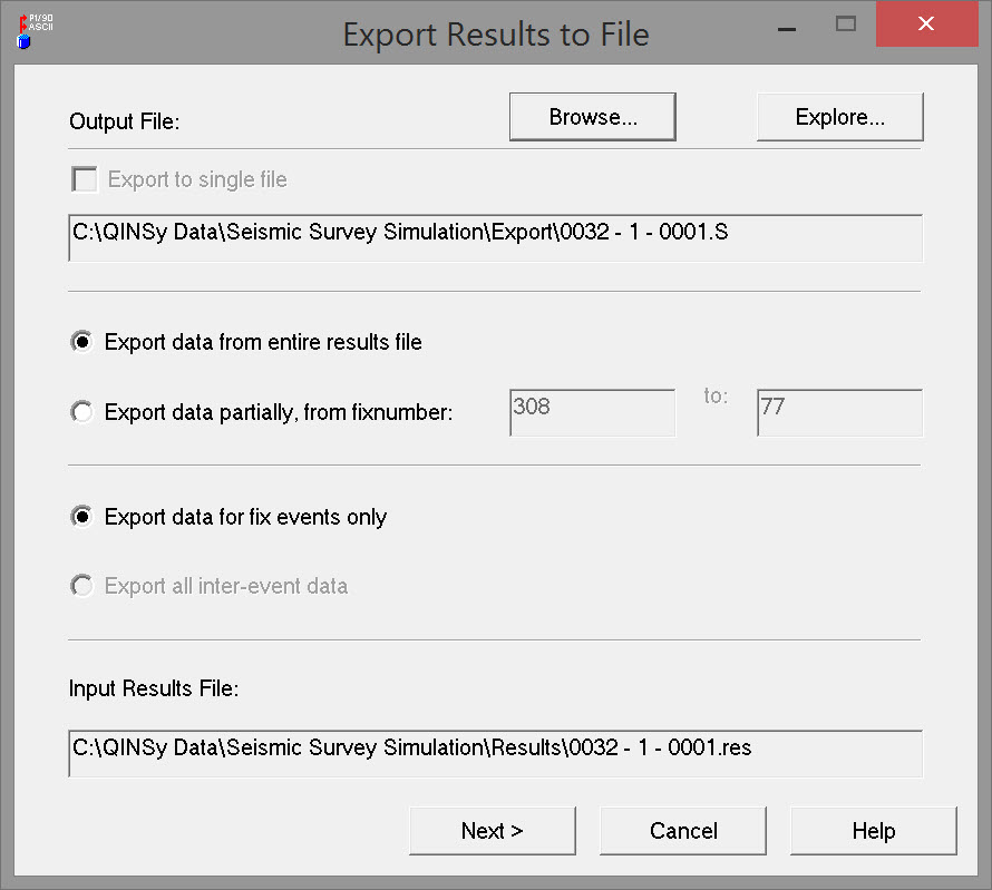
Output File | |
|---|---|
| Export to single file | This is an option to combine the SPS output of multiple files (selected in the Raw Data Manager) into a single file. Selecting this option activates the Browse button which opens the Project Export folder. Give the combined SPS file a name. Clicking on the Explore button also opens the Project Export folder for inspection only. |
| Export data from entire results file | All data is stored in the results file, from the first recorded fix to the last. Exactly what is stored depends on other settings. See below. |
| Export data partially, from fix number | By default the first and last fix recorded in the *RES file are displayed. This option allows the fix range to be modified, which might be the case when fixes on the line run-in and run-out are not required in the SPS file. For example the first fix shown in the picture above is 94, but the fix at SOL was 101. The fix at EOL was 500 but another 25 fixes were recorded to accommodate the run-out. |
| Export data for fix events only | *.DB files contain all the raw data recorded and *.RES files contain all positions calculated. This option restricts Fix data output to the subset of positions computed at the time of each shot-point. |
| Export all inter-event data | *.DB files contain all the raw data recorded and *.RES files contain all positions calculated. This option exports all the positions calculated, the frequency of which is based on the triggering system used for the computation cycle. |
| Input Results File | Lists the *.RES file associated with the *.DB file selected in the Raw Data Manager. |
Page 2 - SPS Node Selection
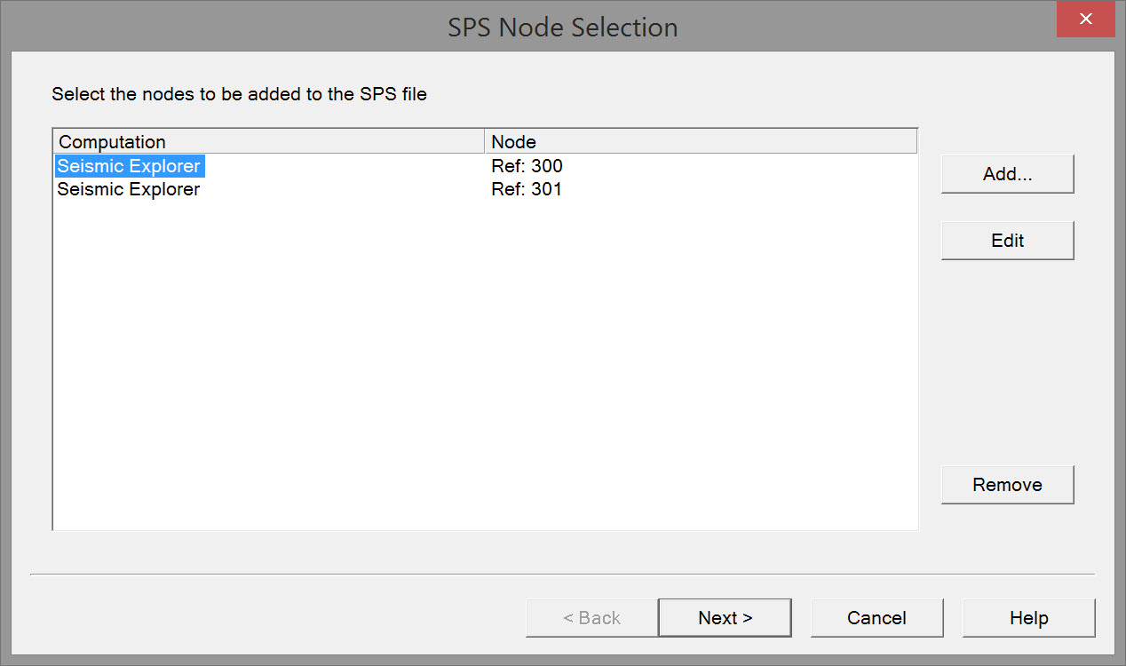
Initially the dialog box is empty. The purpose is to Add all the nodes for which a position is needed in the SPS file.
Add - opens the selection window. Simply choose the Computation and Node on the Gun Array which represents the center of source.
Press OK.
Note that this dialog box is mis-labeled as 'Select P1/90 Node'. However that does not affect the SPS export.
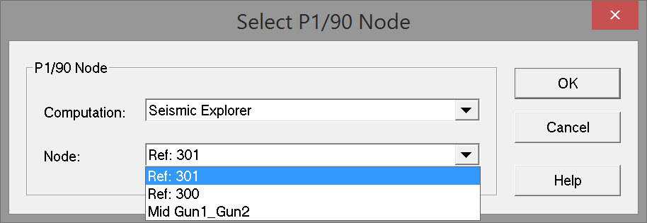
Edit - click on the node to be edited and then click Edit. The same 'Select P1/90 Node' window opens.
Remove - click on the node to be removed and then click Remove.
Page 3 - SPS Setup Nodes
All the nodes selected on the previous page are listed in the order they were selected. The values initially displayed in columns Code, Number and Index will probably not make much sense at all. The task on this page is to assign correct SPS codes and IDs to each node.
QINSy uses a limited set of 'source ' codes - V, E, A, W, and S.
The official SPS format supports these SPS Point codes :
Receiver Codes: "G1".."G9" "H1".."H9", "R1".."R9".
Source Codes: "V1".."V9", "E1".."E9", "A1".."A9", "W1".."W9", "S1".."S9".
Other Codes: "PM" - permanent marker, "KL" - kill or omit point.
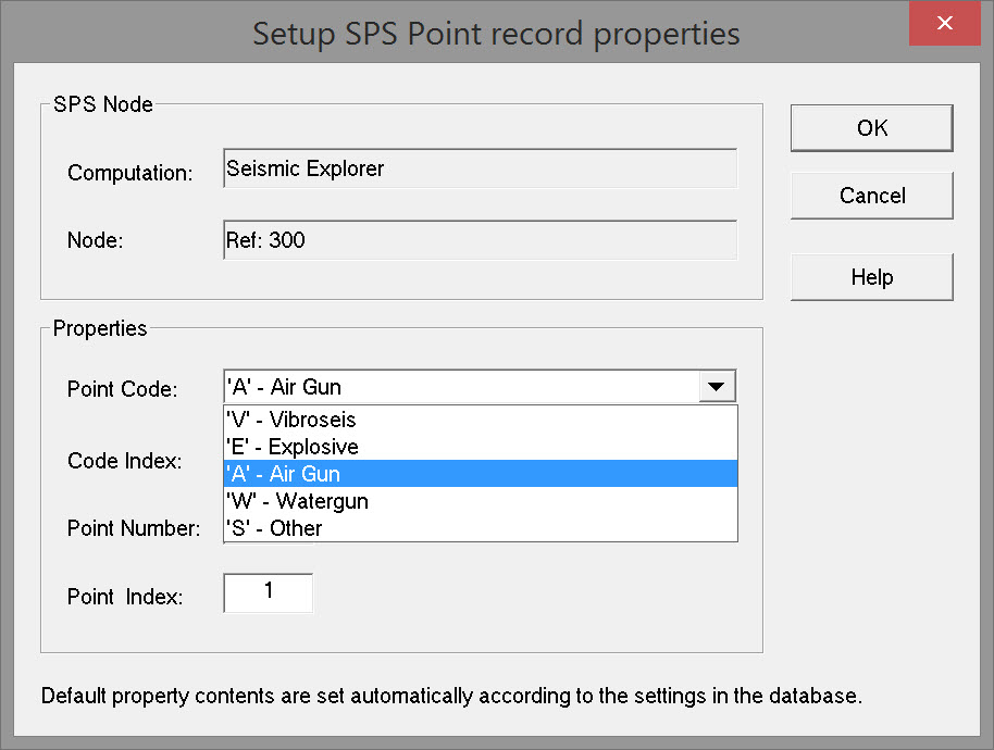
| SPS Node | |
|---|---|
| Computation | Simply shows the computation associated with the node as selected on the previous page of the wizard. |
| Node | Simply shows the node selected. |
| Properties | |
|---|---|
| Point Code | A shotpoint (source) or receiver (hydrophone/geophone) code which is defined in the header by a table that describes the characteristics of the source and receiver:
QINSy supports only source codes. V = Vibroseis |
| Code Index | Enter a number 1....9. For example if two airguns were used one would have code index 1 and the other code index 2. V1..to.V9 for vibroseis |
| Point Number | Identifier for the shotpoint number defined as the center of the source. In QINSy corresponding to the 'fix number'. |
| Point Index | Identifier for the shotpoint or receiver index. The point index for the first shoot of a line would be '1'. If the line is re-shot, the point index increments to '2', and so on. Shotpoint: To be 1 for original shot within the grid cell denoted by fields 2 and 3, and be incremented by 1 for each subsequent shot within the same grid cell. Exceptions: shots to be vertically stacked (unsummed vibroseis). Receiver: To be 1 for the original positioning of a receiver group, and be incremented by 1 every time the receiver group is moved or repositioned, even when put back to any previous position. |
Page 4 - SPS Header Setup
Each SPS file should start with a number of header records which contain information about, and parameters controlling, all of the data records which follow.
Most Header records are automatically populated with information entered into the Template Database. Some remains to be entered.
Initially the dialog box is empty. Click on the header record type (Instrument, Receiver or Source).
Click on on an "H" record number and type in the contents.
Click on "Update Header Record" to fill the Contents field.
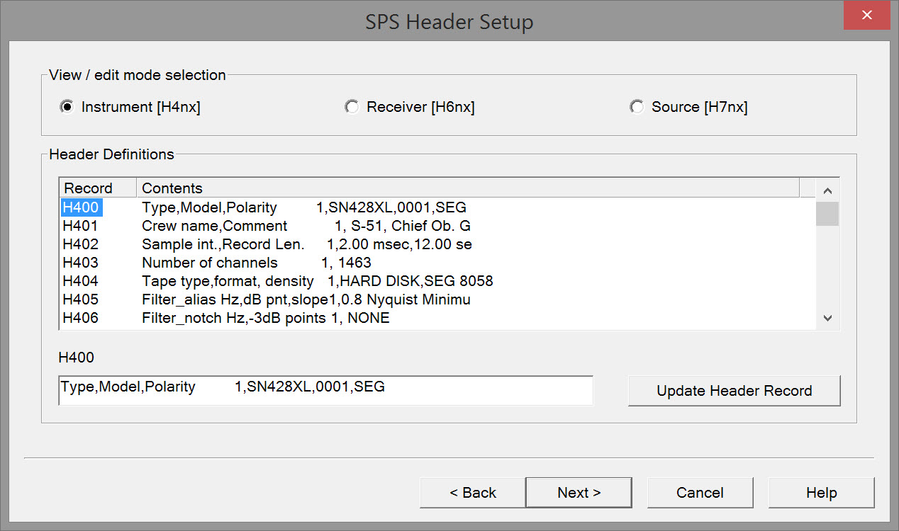
| View/Edit Mode Selection | |
|---|---|
| Instrument | Seismic instrument header records: The user must define the set of code definitions for surveys, areas and vintages. Header record types H400-H419 are to be used to define tables for the first instrument code, and H420-H439 for the second up to H560-H579 for the ninth code. The instrument code is for example '1' to '9'.H400 Type,Model,Polarity The type and model name of seismic recording instrument, the unique model number of the instrument and the polarity defined as SEG or NON SEG. The definition of SEG is "A compression shall be recorded as a negative number on tape and displayed as a downward deflection on monitor records". H401 Crew name,Comment The name of the crew and any other comments. H402 Sample int.,Record Length The recording sample rate and the record length on tape. H403 Number of channels The number of channel per record. H404 Tape type,format,density The type of tape (9track or cartridge), recording format of the data on tape and the recording density. H405 Filter_alias Hz,dB pnt,slope The anti alias or high cut filter setting of the recording instrument or field boxes specified in Hertz, the dB level at the frequency value and the filter slope in dB per octave. H406 Filter_notch Hz,-3dB points The centre frequency of the notch filter setting of the recording instrument or field boxes specified in Hertz and the frequency values at the -3dB points. H407 Filter_low Hz,dB pnt,slope The low cut filter setting of the recording instrument or field boxes specified in Hertz, the dB level at the frequency value and the filter slope in dB per octave. H408 Time delay,FTB-SOD app Y/N The value of any time delay and if the delay between field time break and start of data has been applied to the seismic data recorded on tape. H409 Multi component recording Describes the components being recorded and their recording order on consecutive channels, allowed values are 'X','Y','Z'. H410 Aux. channel 1 contents Describes the contents of a auxiliary channel. H411 Aux. channel 2 contents H412 Aux. channel 3 contents H413 Aux. channel 4 contents H414 Spare | H419 Spare |
| Receiver | Seismic receiver header records: Examples of possible codes: H600 Type,model,polarity The type (land geophone, marsh geophone, hydrophone), model name of seismic detector and the polarity defined as SEG or NON SEG. The definition of SEG is "A compression shall be recorded as a negative number on tape and displayed as a downward deflection on monitor records". Example: G1,SM-4,1234,SEG; H601 Damping coeff,natural freq. H602 Nunits,len(X),width(Y) The number of elements in the receiver group, the in-line and the cross-line dimension of the receiver group pattern. H603 Unit spacing X,Y The distance between each element of the receiver group, in-line (X), and cross-line (Y). H604 Spare | H609 Spare |
| Source | Seismic source header records: Examples of possible codes: H700 Type,model,polarity Source type (explosive,air gun etc), make or model, and the polarity defined as SEG or NON SEG. The definition of SEG is "A compression shall be recorded as a negative number on tape and displayed as a downward deflection on monitor records". H701 Size,vert. stk fold The total charge size, force or air volume of the source pattern, the vertical fold of stack or number of sweeps per VP. H702 Nunits,len(X),width(Y) The number of elements in the source pattern, the in-line and the cross-line dimension of the source pattern. H703 Unit spacing X,Y The distance between each element of the source pattern, in-line (X), and cross-line (Y). Following records are only required if source type = air gun A1..A9 or water gun W1..W9 H717 Air pressure psi The nominal operating air pressure. H718 No. sub arrays,nom depth The number of sub arrays and the nominal towing depth. H719 Spare |
| Record | Header record specification: The general format for a header record shall be: Cols Format a. Record identifier "H" 1 A1 b. Header record type 2-3 I2 c. Header record type modifier 4 I1 d. Parameter description 5-32 7A4 e. Parameter data 33-80 per format description |
| Contents | Includes the 'Parameter Description' and the 'Parameter Data'. Automatically populated from *.DB and *.RES files. Cols Format a. Record identifier "H" 1 A1 b. Header record type 2-3 I2 c. Header record type modifier 4 I1 d. Parameter description 5-32 7A4 e. Parameter data 33-80 per format description |
| Update Header Record | Command to save data entries. |
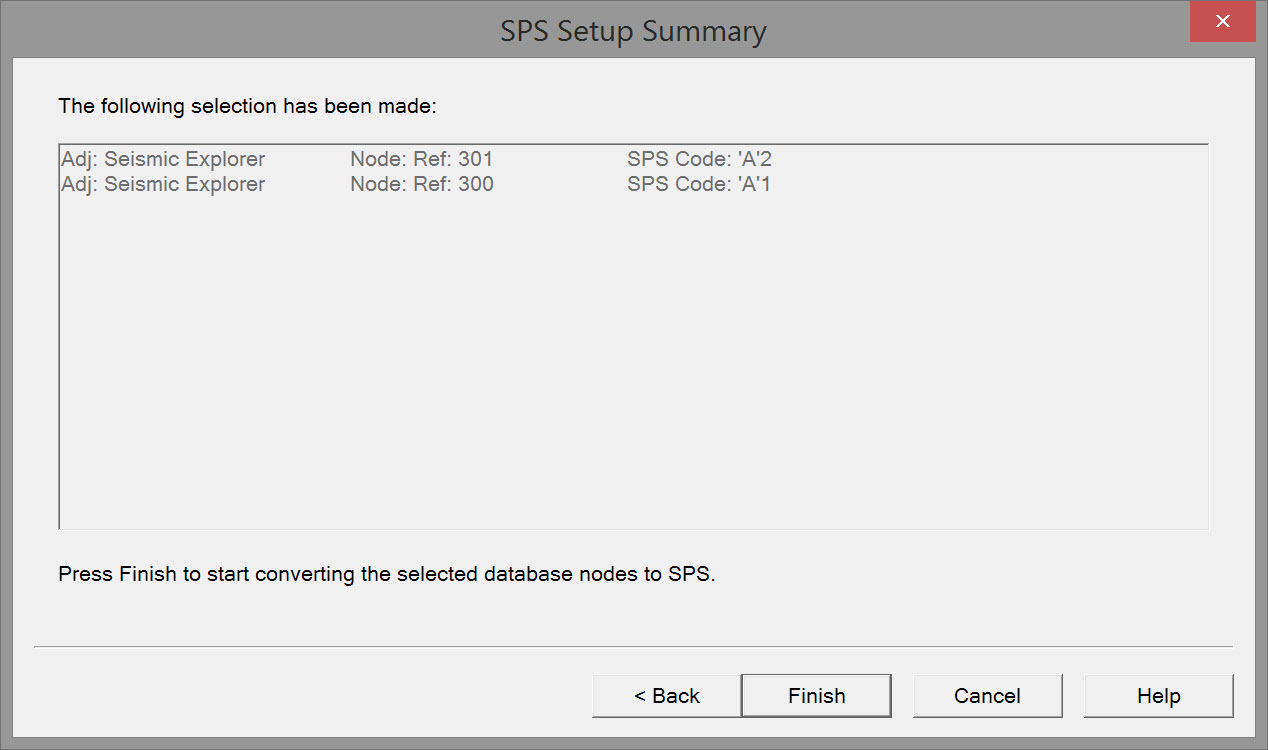
Page 5 - SPS Setup Summary
Check the summary information and press Finish to generate the SPS file(s).
Return to: 43514724.
Return to: Exporting Towed Streamer Seismic Positioning Data .
SPS File Types
Coordinates and elevations of geophysical lines may be determined by interpolation between observed break points in the line. The point files contains coordinates and elevations of all geophysical points (observed and interpolated) and of all permanent markers. The shotpoint and relational files are to be sorted chronologically, and the receiver file is to be sorted in ascending sequence of line, point and point index numbers.
In order to avoid ambiguities each physical position in the field (shotpoint or receiver group) must have a unique name.
SPS format is a set of three files called Receiver file, Source file, Cross reference file and an optional fourth file for comments. In addition to the comment file comments can be entered in each of the three files as part of the header and is indicated by starting with the letter H.
Receiver file (R records)
Receiver file contains the information about the geophones their type, position (Easting, Northing, Elevation) and their ID.
"Point Records" with details of receiver groups or permanent markers.
Receiver Codes:
G1..to.G9 for geophones
H1..to.H9 for hydrophones
R1..to.R9 for multi comp. and other types
Source file (S records)
Source file contains the information about the Seismic source, its position and their ID.
"Point Records" with details of shotpoints (power source).
Source Codes:
V1..to.V9 for vibroseis
E1..to.E9 for explosive
A1..to.A9 for air gun
W1..to.W9 for water gun
S1..to.S9 for other types
Cross reference file (X records)
Cross reference file (also known as relational file) or in short, X file, is basically a relational file relating the source and the receiver when the shot occurred. It contains the details about the Shot ID, Source and receivers associated with that particular shot ID.
"Relation Records" specifying for each shotpoint its record number and the relation between recording channel numbers and receiver groups
Versions
- The first version of SPS adopted by SEG is now referred to as SPS rev0
- The recent version of SPS is SPS rev2.1 (Jan 2006).
SPS Header Records
Each file shall start with a number of header records which contain information about, and parameters controlling, all the data records which follow.
The general format for a header record shall be:
Cols Format
a. Record identifier "H" 1 A1
b. Header record type 2-3 I2
c. Header record type modifier 4 I1
SPS Point Records
Specification
item | definition of field | cols | format | min. to max | default | just. | units |
|---|---|---|---|---|---|---|---|
1 | record identification | 1-1 | A1 | “S” or “R” | none | n/a | |
2 | line name | 2-11 | F10.2 | -999999.99 to 9999999.99 | none | right | |
3 | point number | 12-21 | F10.2 | -999999.99 to 9999999.99 | none | right | |
+ | 22-23 | blank | blank | ||||
4 | point index | 24-24 | I1 | 1 to 9 | 1 | right | |
*5 | point code | 25-26 | A2 | A# | none | Left | |
6 | static correction | 27-30 | I4 | -999 to 999 | blank | right | ms |
7 | point depth | 31-34 | F4.1 | 0 to 99.9 | 0 | right | header defined |
8 | seismic datum | 35-38 | I4 | -999 to 9999 | 0 | right | header defined |
9 | uphole time | 39-40 | I2 | 0 to 99 | blank | right | ms |
10 | water depth | 41-46 | F6.1 | 0 to 9999.9 | blank | right | header defined |
11 | map grid easting | 47-55 | F9.1 | none | none | right | |
12 | map grid northing | 56-65 | F10.1 | none | none | right | |
13 | surface elevation | 66-71 | F6.1 | -999.9 to 9999.9 | none | right | header defined |
14 | day of year | 72-74 | I3 | 1 to 999 | none | right | |
15 | time “hhmmss” | 75-80 | 3I2 | 000000 to 235959 | none | n/a |
* Example Point codes :
"PM" - permanent marker, "KL" - kill or omit point
"G1".."G9" "H1".."H9", "R1".."R9" - receiver codes
"V1".."V9" "E1".."E9", "A1".."A9","W1".."W9",
"S1".."S9". - source codes
Description
| Item | Description |
|---|---|
| 2 | Line name: Identifier for the shotpoint or receiver line. It is a numeric number with the format of F10.2. If no decimal point is provided it should be taken as implied. It can be composed of a block or strip number and a line number. The internal format of this field must be defined in the header. |
| 3 | Point number: Identifier for the shotpoint or receiver group number defined as the centre of the source or receiver array as staked out in the field. The value should be read as a numeric F10.2 and be right justified. |
| 4 | Point index: Identifier for the shotpoint or receiver index. Shotpoint: To be 1 for original shot within the grid cell denoted by fields 2 and 3, and be incremented by 1 for each subsequent shot within the same grid cell. Exceptions: shots to be vertically stacked (unsummed vibroseis). Receiver: To be 1 for the original positioning of a receiver group, and be incremented by 1 every time the receiver group is moved or repositioned, even when put back to any previous position. |
| 5 | Point code: A shotpoint or receiver code which is defined in the header by a table that describes the characteristics of the source or receiver group used at the point. |
| 6 | Static correction: The shotpoint or receiver static correction defined as a static time shift in Msec. that has been computed in the field to correct any seismic recording for the effects of elevation, weathering thickness, or weathering velocity at the point. The correction should be with reference to the seismic datum as defined by field 8 of this record. If no static was computed leave 'blank'. |
| 7 | Point Depth: The depth of the shotpoint source or receiver group. Header defined units with respect to the surface down to the top of the charge or vertical receiver array. When the surface elevation can vary with time (eg. a tidal water surface), then for shotpoints the value should be at the time of recording, and for receivers at the time of recording of the first shotpoint into that receiver. (see figures 3 and 4) |
| 8 | Seismic datum: Header defined units as an offset to the datum defined in header record H17. It is +ve when above datum , -ve when below datum or zero when at datum. If the seismic datum is equal to H17, enter zero. (see figures 3 and 4) |
| 9 | Uphole Time: Defined for a shotpoint as the vertical travel time to surface, recorded in msec and is always positive or zero. If no uphole was recorded leave 'blank' Not defined for receiver leave 'blank', unless a reverse uphole is taken then the shotpoint definition applies. |
| 10 | Water depth: Header defined units of the measured (or reliably determined) height of water surface above the sea bed or water bottom. In case the water depth varies in time by more than one meter (eg. tidal areas) then for shotpoints the value should be at the time of recording and for receivers at the time of recording of the first shotpoint into that receiver. The water depth value is always positive. (see figures 3 and 4) |
| 11 | Map grid easting: The easting for the point, in the coordinate system defined by header record H13. |
| 12 | Map grid northing: The northing for the point, in the coordinate system defined by header record H13. To accommodate large TM northing values for surveys straddling the equator, this field format has one more digit than UKOOA P1/90. |
| 13 | Surface elevation: The topographical surface with respect to the vertical datum defined by header record H17. The surface elevation is +ve when above datum , -ve when below datum or zero when at datum. When the surface elevation with respect to the datum can vary with time (eg. a tidal water surface) Then for shotpoints the value should be at the time of recording, and for receivers at the time of recording of the first shotpoint into that receiver. (see figures 3 and 4) |
| 14 | Day of year: The Julian day. For shotpoints the value should be the day of recording, and for receivers the day of recording of the first shotpoint into that receiver. When the survey continues into the next year, the day should keep increasing and not be reset to zero - 1st January would then be 366 or 367. |
| 15 | Time hhmmss: The time taken from the clock of the master seismic recording instrument. For shotpoints the value should be the time of recording, and for receivers the time of recording of the first shotpoint into that receiver. |
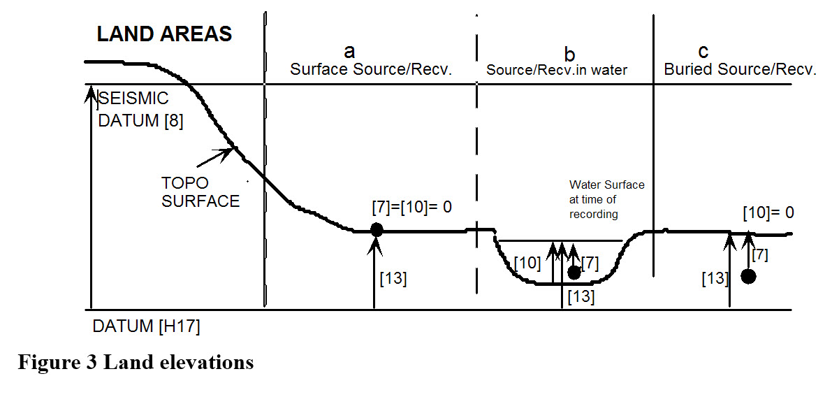
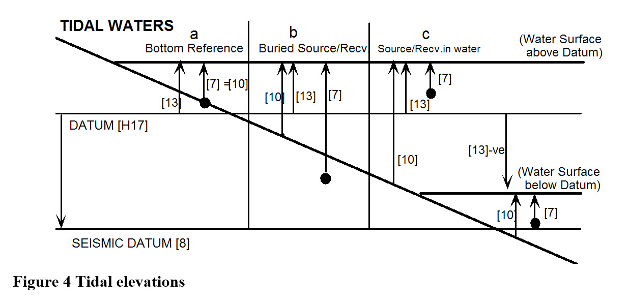
[7] = POINT DEPTH
[10] = WATER DEPTH at time of recording
[13] = SURFACE ELEVATION w.r.t. DATUM [H17]
[x] = Item number in POINT RECORD
Return to: 43514724
Return to: Exporting Towed Streamer Seismic Positioning Data
