
On this page:
General
MGD77 is an exchange format for marine geophysical data (bathymetry, magnetics, and gravity).
It is intended to be used for the transmission of data to and from a data center and may be useful for the exchange of data to and from a data center and may be useful for the exchange of data between marine institutions.
Each data record may include time, navigation, bathymetry, magnetic s, gravity, and seismic line information.
Info
The format description can be found here: http://www.ngdc.noaa.gov/mgg/dat/geodas/docs/mgd77.txt and lower on this page.
Qinsy Export Wizard
In the Raw Data Manager highlight the files for export and select 'Actions - Export', or click on the icon 
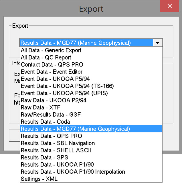
Select 'Results Data - MGD77 (Marine Geophysical)' and click OK to open the export wizard.
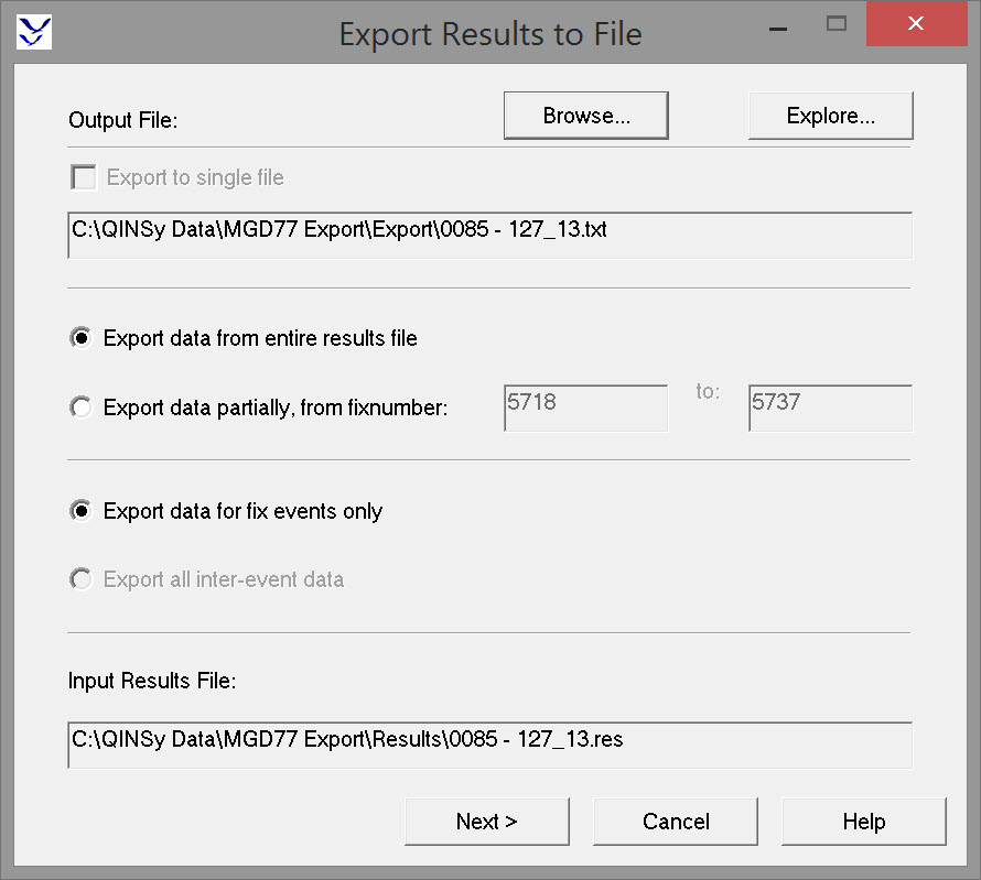
Page 1 - Export Results to File
|
Output File |
|
|---|---|
|
Export to single file |
This is an option to combine the MGD77 output of multiple files (selected in the Raw Data Manager) into a single file.
Selecting this option activates the Browse button which opens the Project Export folder. Give the combined MGD77 file a name. Clicking on the Explore button also opens the Project Export folder for inspection only. |
|
Export data from entire results file |
All data is stored in the results file, from the first recorded fix to the last. Exactly what is stored depends on other settings. See below. |
|
Export data partially, from fix number |
By default the first and last fix recorded in the *RES file are displayed. This option allows the fix range to be modified, which might be the case when fixes on the line run-in and run-out are not required in the MGD77 file. |
|
Export data for fix events only |
*.DB files contain all the raw data recorded and *.RES files contain all positions calculated. This option restricts data output to the subset of positions computed at the time of each fix. |
|
Export all inter-event data |
*.DB files contain all the raw data recorded and *.RES files contain all positions calculated. This option exports all the positions calculated, the frequency of which is based on the triggering system used for the computation cycle. |
|
Input Results File |
Lists the *.RES file associated with the *.DB file selected in the Raw Data Manager.
|
Click Next
Page 2 - MGD77 Format Selection
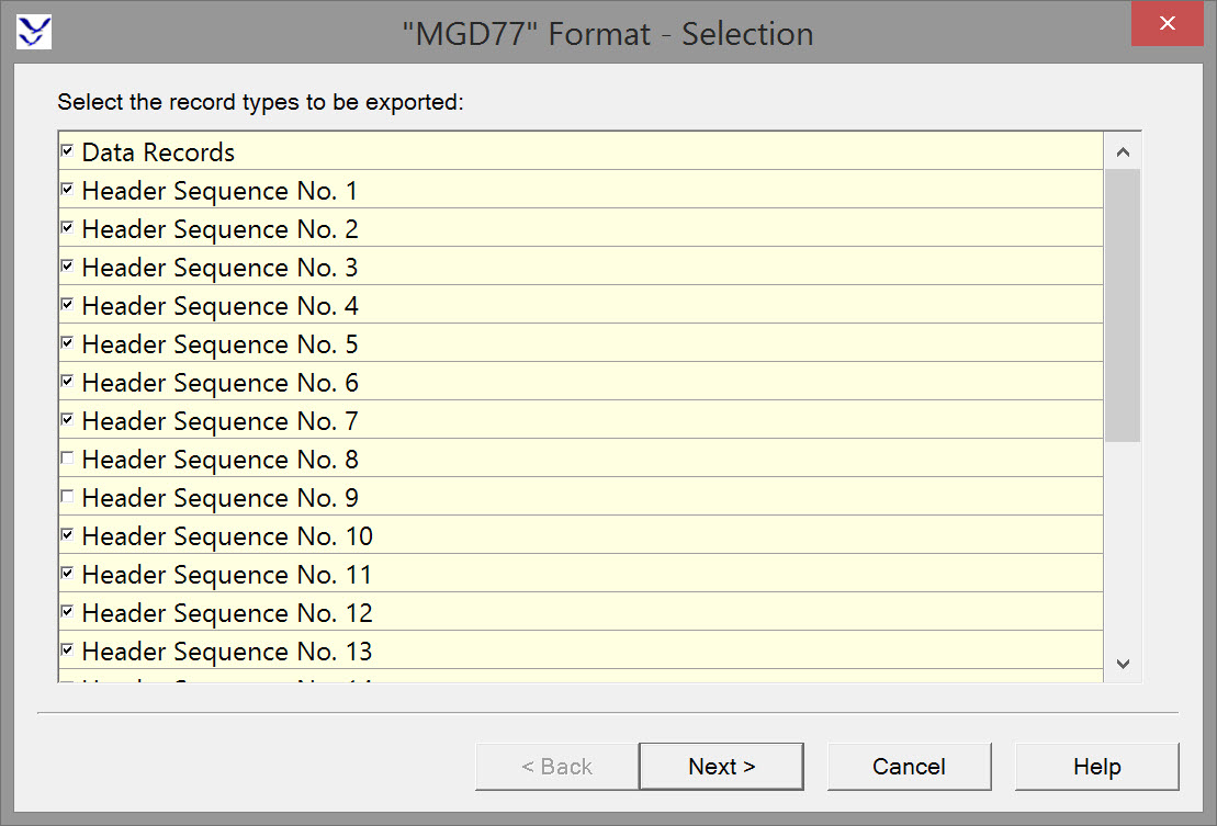
On this page decide whether or not to to export Data Records.
On this page decide whether or not to to export Header Records and which ones (Sequence 1-24).
Data Record
The Data Record presents underway marine geophysical data in a correlative manner. Geophysical data (bathymetry, magnetics, and gravity) and seismic identification (shot-point identification) are presented with a corresponding time and position.
Header Record
The purpose of the Header Record is to document both the content and structure of the geophysical data contained within subsequent data records. In general, documentation that is constant throughout the survey will be in the Header Record, while documentation that is variable will be in the Data Records.
The following table provides an indication of what data is contained in each record type. Please refer to the full MGD77 Format description for further details/explanations.
|
Format Selection |
|
|---|---|
|
Data Records |
The data record presents underway marine geophysical data in a correlative manner. Geophysical data (bathymetry, magnetics, and gravity) and seismic identification (shot-point identification) are presented with a corresponding time and position. |
|
Header Sequence 1 |
RECORD TYPE - Set to "4"
|
|
Header Sequence 2 |
COUNTRY
|
|
Header Sequence 3 |
PROJECT (e.g., "SURVOPS 6-69", "INDOPAC, Leg3")
|
|
Header Sequence 4 |
SURVEY DEPARTURE DATE (YYMMDD)
|
|
Header Sequence 5 |
NAVIGATION INSTRUMENTATION (e.g. "SAT/LORAN A/SEXTANT")
|
|
Header Sequence 6 |
BATHYMETRY INSTRUMENTATION
|
|
Header Sequence 7 |
MAGNETICS INSTRUMENTATION (e.g., "PROTON PRECESSION MAG-GEOMETRICS G-801")
|
|
Header Sequence 8 |
GRAVITY INSTRUMENTATION (e.g., "L and R S-26")
|
|
Header Sequence 9 |
SEISMIC INSTRUMENTATION
|
|
Header Sequence 10 |
FORMAT TYPE
|
|
Header Sequence 11 |
FORMAT DESCRIPTION Continued
|
|
Header Sequence 12 |
GENERAL DIGITIZING RATE OF BATHYMETRY
|
|
Header Sequence 13 |
GENERAL DIGITIZING RATE OF MAGNETICS
|
|
Header Sequence 14 |
GENERAL DIGITIZING RATE OF GRAVITY
|
|
Header Sequence 15 |
DEPARTURE BASE STATION GRAVITY
|
|
Header Sequence 16 |
NUMBER OF 10-DEGREE IDENTIFIERS **
|
|
Header Sequence 17 |
10-DEGREE IDENTIFIERS (Continued)
|
|
Header Sequence 18-24 |
ADDITIONAL DOCUMENTATION
|
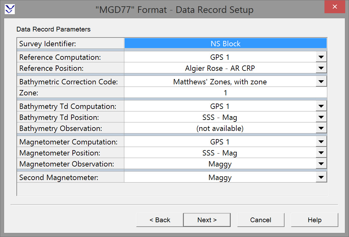
Page 3 - Data Record Setup
|
Data Record Parameters |
|
|---|---|
|
Survey Identifier |
Defaults to the identifier defined in DbSetup. If nothing was entered in DbSetup, enter up to 8 characters.
|
|
Reference Computation |
Choose the computation to be used for output of positions. Computation listed are those defined under Controller - Settings - Computation Settings. |
|
Reference Position |
Choose which node to use as the reference position for output of positions. Nodes listed are those defined in DbSetup. |
|
Bathymetric Correction Code |
This code details the procedure use for determining the sound velocity correction to depth. Various formulas based on theoretical and empirical methods have been proposed since the 1920s. Please refer to A Brief History of Sound Velocity Corrections.
Unspecified - there is no knowledge of what depth correction method was used for the survey. Matthews' Zones, with zone - based on velocities obtained theoretically, D. J. Matthews divided the world’s oceans into discrete areas linking regions with common sound velocity profiles, and constructed a table for each area with the depth corrections to be applied at various depths down the water column. These tables were prepared for the UK Hydrographic Office by Matthews in 1927 and a second edition, extensively revised by the same author, appeared in 1939. The second edition became known as Matthews’ Tables and at the 5th International Hydrographic Conference in 1947, the tables were adopted as the standard for use in all hydrographic offices. Matthews' Zones, no zone - Matthews’ corrections were used to correct depths but the zone number is unspecified in the data record. S. Kuwahara Formula - In 1939 Kuwahara also produced correction tables based on velocities obtained theoretically. Wilson Formula - Formula based on laboratory measurements proposed by Wilson 1960. Del Grosso Formula - Formula based on laboratory measurements proposed by Del Grosso 1973. Carter's Tables - In 1980 a third edition of Echo-Sounding Tables was published by the UK Hydrographic Office to replace Matthews’ Tables. The tables were extensively revised to incorporate the large number of temperature and salinity measurements obtained since 1939. They also used an improved formula for the dependence of sound velocity on temperature and salinity. Computations for the revised tables were carried out by D. J. T. Carter of the Institute of Oceanograhic Sciences, Wormley, UK, using oceanographic station data provided by the U.S. National Oceanographic Data Center, Washington DC. The revised tables, together with a detailed description of their preparation, may be found in Echo-Sounding Correction Tables (1980 3rd Edition), Publication NP139 of the UK Hydrographic Office. In 1982, the 15th International Hydrographic Conference at Monaco decided to adopt the third edition in place of Matthews’ Tables. These tables are applicable for use throughout the world in depths greater than 200 meters. The boundaries of each of the 85 areas lie along exact degrees of latitude and longitude. The tables are expressed in meters and assume an echo-sounder velocity of 1500 m s-1.The tables were computerized by Carter and offer standard velocity-depth corrections for 85 different regions covering the globe. The database consists of algorithms for determining correction zones by latitude-longitude, and interpolation tables for each zone. A digital version of the Echo-Sounding Correction Tables (3rd. Edition) is available to download https://www.bodc.ac.uk/products/software_products/carters_tables/. Other - Any other method as described in header sections. |
|
Zone |
Field only shown when 'Matthews' Zones, with zone' is selected.
|
|
Bathymetry Td. Computation |
Choose the computation to be used for output of echosounder transducer positions. Computation listed are those defined under Controller - Settings - Computation Settings. |
|
Bathymetry Td. Position |
Choose which node to use as the transducer for output of positions. Nodes listed are those defined in DbSetup. |
|
Bathymetry Observation |
Choose the depth observation to output. Observations listed are those defined in DbSetup. |
|
Magnetometer Computation |
Choose the computation to be used for output of the magnetometer positions. Computation listed are those defined under Controller - Settings - Computation Settings. |
|
Magnetometer Position |
Choose which node to use as the magnetometer for output of positions. Nodes listed are those defined in DbSetup. |
|
Magnetometer Observation |
Choose the magnetometer observation to output. Observations listed are those defined in DbSetup. |
|
Second Magnetometer |
Select another magnetometer if employed during the survey. Observations listed are those defined in DbSetup. |
Page 4 - Header Setup
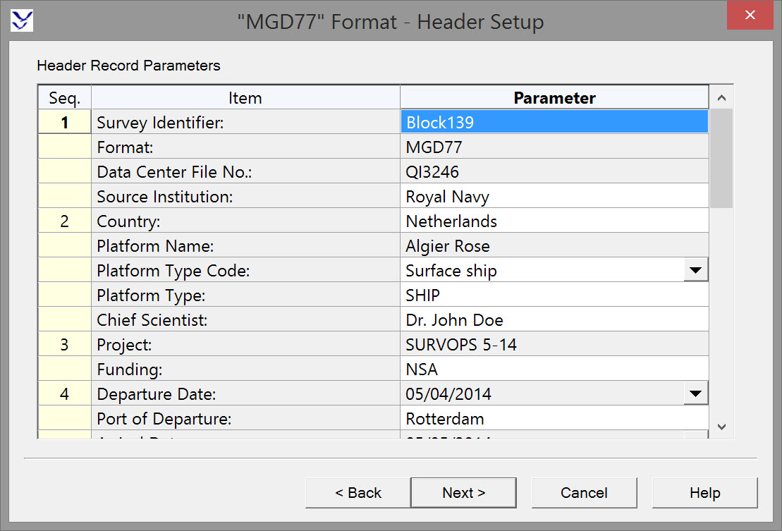
Please be aware that some of the units specified in the QINSy dialog box do not correspond exactly with those specified in the official MGD77 format description. The user should input all values as specified in the dialog box - the export will automatically convert the unit to the official MGTD77 units during the export. In other words the user should always use the unit as seen in the QINSy u/i.
|
Sequence |
Item |
Parameter |
|---|---|---|
|
1 |
Survey identifier: |
Defaults to the identifier defined in DbSetup. If nothing was entered in DbSetup, or a different identifier is wanted, enter up to 8 characters.
|
|
|
Format: |
Read from the Format Name entered in DbSetup - General - Media & Format Specification. Typically this would be set to"MGD77".
|
|
|
Data Center File No.: |
Read from the Project Name entered in DbSetup - General - Project Information.
|
|
|
Source Institution: |
Read from the Project Name entered in DbSetup - General - Company Information.
|
|
2 |
Country: |
Enter name of country (up to 18 characters). |
|
|
Platform Name: |
Name of towing vessel copied from template database. Changeable (up to 21 characters). |
|
|
Platform Type Code: |
Select one of the following from the drop down list:
|
|
|
Platform Type: |
Enter name (e.g., "SHIP","PLANE", "SUB", etc.). Up to 6 characters. |
|
|
Chief Scientist(s): |
Enter name (up to 32 characters). |
|
3 |
Project: |
Read from the Survey Type/Location entered in DbSetup - General - Project Information.
|
|
|
Funding: |
Enter name of funding source (up to 20 characters). |
|
4 |
Departure Date: |
Read from the Start Date entered in DbSetup - General - Project Information.
|
|
|
Port of Departure: |
Enter up to 32 characters. |
|
|
Arrival date: |
Read from the End Date entered in DbSetup - General - Project Information.
|
|
|
Port of Arrival: |
Enter up to 30 characters. |
|
5 |
Navigation Instrument: |
Entry is copied from the Reference Computation field in the Data Record, as selected on the previous page of the wizard.
|
|
|
Geodetic Datum: |
Defaults to name of Survey Datum defined in the DbSetup template database. Changeable (up to 38 characters). |
|
6 |
Bathymetry Instrument: |
Entry is copied from the Bathy Observation field in the Data Record, as selected on the previous page of the wizard.
|
|
|
Add. Forms of Bathy Data: |
Enter any additional forms in which the bathy data is stored (e.g., "Microfilm","Analog Records").
|
|
7 |
Magnetics Instrument: |
Entry is copied from the Magnetometer Observation field in the Data Record, as selected on the previous page of the wizard.
|
|
|
Add. Forms of Magnetics Data: |
Enter any additional forms in which the Magnetics data is stored (e.g. "Analog Records").
|
|
12 |
Bathy Digitizing Rate (second): |
Output rate of digital data in seconds as read from Event Interval entered in Controller - Settings - Session Setup - Fixing when Event Mode is set to Time. |
|
|
Bathy Sampling Rate: |
Describe the digital data output rate. Enter up to 12 characters e.g. "1/second". |
|
|
Sound Velocity m/sec: |
Read from Propagation Velocity Used field as defined in DbSetup - Echosounder System.
|
|
|
Bathy Datum: |
Select which datum was used for the survey: 00 - No correction applied
|
|
|
Interpolation Scheme: |
This field allows for a description of the interpolation scheme used, should some of the data records contain interpolated values (e.g., "5-MINUTE INTERVALS AND PEAKS AND TROUGHS").
|
|
13 |
Magnetics Digitizing Rate (second): |
Output rate of digital data in seconds as read from Event Interval entered in Controller - Settings - Session Setup - Fixing when Event Mode is set to Time. |
|
|
Magnetics Sampling Rate: |
Describe the digital data output rate.
|
|
|
Sensor Tow Distance (meters): |
Enter the nominal distance from the navigation reference to the leading sensor.
|
|
|
Estimated Sensor Depth (meters): |
Enter the nominal depth of the leading magnetic sensor.
|
|
|
Horizontal Sensor Separation (meters): |
Enter the nominal separation distance between the two sensors (if a second sensor is used).
|
|
|
Reference Field Code: |
This is the reference field used to determine the residual magnetics. The primary goal in the reduction of magnetic survey data is the accurate determination of the residual (or anomalous) magnetic field associated with the geological structures or ferrous artifacts being investigated.
Various models to simulate the patterns of the earth's geomagnetic field have been proposed. Because the Earth's magnetic field is constantly changing, models are periodically updated.
00 - Unused
|
|
|
Reference Field: |
The selection made for 'Reference Field Code' is repeated here. |
|
|
Applying Residual Field Method: |
The procedure used in applying this reduction to the data.
|
|
18 |
Additional Documentation: |
Information concerning the survey not contained in header fields. |
|
19 |
Additional Documentation: |
Information concerning the survey not contained in header fields. |
|
20 |
Additional Documentation: |
Information concerning the survey not contained in header fields. |
|
21 |
Additional Documentation: |
Information concerning the survey not contained in header fields. |
|
22 |
Additional Documentation: |
Information concerning the survey not contained in header fields. |
|
23 |
Additional Documentation: |
Information concerning the survey not contained in header fields. |
|
24 |
Additional Documentation: |
Information concerning the survey not contained in header fields. |
Page 5 - Setup Summary
Press Finish to generate the MGD77 file.
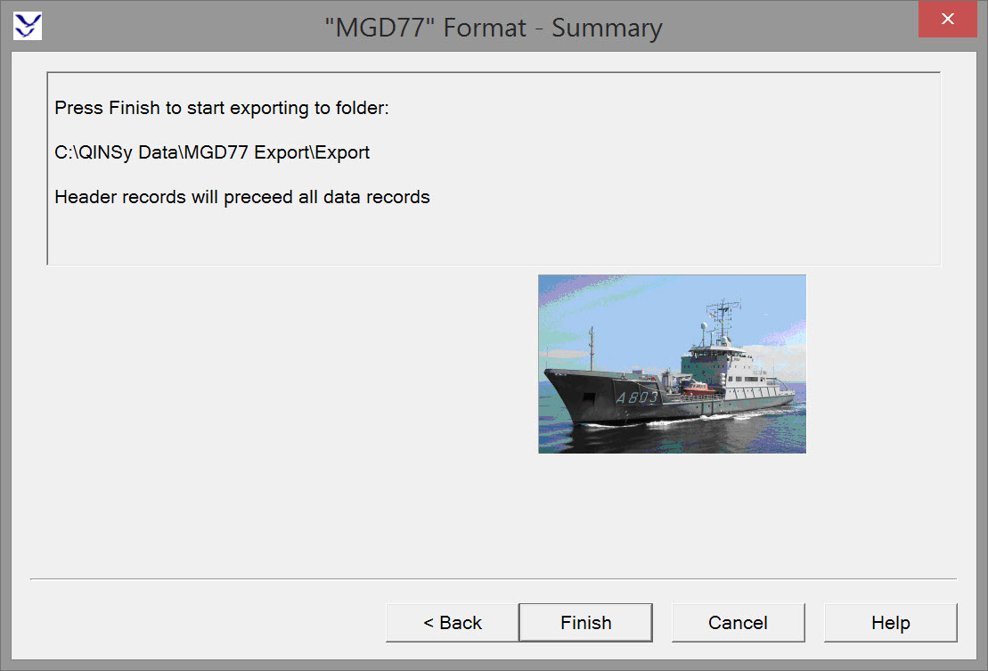
An illustration, containing all relevant settings
Return to: top of page.
Return to: Exporting Towed Streamer Seismic Positioning Data.
MGD77 Format Description
Introduction
In January of 1977, a group of 24 geophysical data managers from academia, government, industry and foreign countries participated in a workshop at the National Geophysical Data Center (NGDC) in Boulder, Colorado. The "Workshop for Marine Geophysical Data Formats" established the basic outline of a new format for the exchange of digital underway geophysics data. A six member task force was formed to work with NGDC in implementing the decisions of the workshop into the new format. By the end of 1977 the "MGD77" format was being disseminated by NGDC as its standard exchange format.
The "MGD77" format has experienced much success over the past 20 years. It has been sanctioned by the Intergovernmental Oceanographic Commission (IOC) as an accepted standard for international data exchange, and it has been translated into French, Japanese, and Russian. Most contributors of data to NGDC now send transfer data over the internet in the "MGD77" format.
This newest revision makes the MGD77 format "Year 2000 Compliant", ensuring it's use into 21st Century.
General Description
The digital format presented, and referred to as "MGD77", is an exchange format for marine geophysical data (bathymetry, magnetics, gravity and seismic navigation) It is intended to be used for the transmission of data to and from a data center and may be useful for the exchange of data between marine institutions. Data is to be exchanged in files, generally a header (documentation) file and a data file for each survey operation. Generally each survey operation is a port-to-port operation of a survey vessel, but in some cases several port-to-port operations of the same vessel are combined into a single survey operation, especially if this is the manner of organizing the data at the contributing institution. Data may be exchanged via the Internet or on various mass storage devices such as 8mm or 9 track tapes, removable disks. The National Geophysical Data Center uses CD-ROM disks as its chief method of distribution of these data.
Data Exchange
1. For exchange of MGD77 data via mass storage files on magnetic or disk media participants shall establish type and format of the media to be exchanged.
2. Each survey operation shall be contained in one file with Header and Data Records, or in 2 files, one Header file and one Data Record file. If the media is too small to contain one survey the data may be continued on a second media.
3. Each survey operation shall have one MGD77 Header consisting of 24 80-character logical records.
4. The MGD77 data records are sequentially and chronologically organized until the end of the file. The data records are 120 logical characters.
5. A survey is defined as all observations that conveniently constitute a survey operation (e.g., a port-to-port survey or in some cases several surveys). A survey file(s) ideally should not span two media.
6. For sequential files, the MGD77 Header shall consist of 24 sequential records of 80 logical characters each separated by an end-of-record character(s) and, if the data records are in the same file, the Header shall be at the beginning of the file. The MGD77 Data Records shall be 120 logical characters each.
7. 9 Track tapes should be recorded as ASCI 1600 or 6250 BPI. The tape structure consists of physical records of 1920 characters each, a header followed by data records, separated by inter-record gaps (IRG) and organized into files. The files are separated by end-of-file (EOF) marks (sometimes called tape marks).
THE HEADER RECORD
The purpose of the Header Record is to document both the content and structure of the geophysical data contained within subsequent data records. In general, documentation that is constant throughout the survey will be in the Header Record, while documentation that is variable will be in the Data Records.
For sequential files, the MGD77 Header consists of 24 80-character sequential records. For 9 track magnetic tapes the MGD77 Header is a physical record (block) consisting of 1,920 characters. In both cases the data records follow immediately with no intervening end-of-file marks.
The Header Record contains fields which are both fixed and freely formatted. All field lengths within the Header that have not been coded with information should be blank filled, and all plain language statements should be left justified. The Header consists of a "sequence" of twenty four 80-character images. The field lengths within the Header Records are designed to allow one to read the information (from magnetic tapes) as a series of 120 character logical records -- the same logical record length as the data records.
To help the marine geophysical community prepare this documentation, a coding pad is available free of charge from the National Geophysical Data Center.
*** CHANGES SINCE LAST REVISION ***
Several changes in the MGD77 Format were required in order to make the format "Year 2000 Compliant" (Y2K Compliant):
|
SEQ. |
DESCRIPTOR |
CHANGE |
|---|---|---|
|
01 |
RECORD TYPE |
Change from "1" to "4" |
|
01 |
FILE CREATION DATE |
Change to include century
|
|
01 |
SOURCE INSTITUTION |
Change from 41 chars (col 38-78) to 39 chars (col 40-78) |
|
04 |
SURVEY DEPARTURE DATE |
Change to include century
|
|
04 |
PORT OF DEPARTURE |
Change from 34 chars (col 7-40) to 32 chars (col 9-40) |
|
04 |
SURVEY ARRIVAL DATE |
Change to include century
|
|
04 |
PORT OF ARRIVAL |
Change from 32 chars (col 47-78) to 30 chars (col 49-78) |
Format Conventions for the Header Record:
1. All decimal points are implied.
2. Leading zeros and blanks are equivalent.
3. Unknown or unused fields are to be blank filled.
4. All "corrections", such as time zone, diurnal magnetics, and Eotvos, are understood to be added (e.g., time-zone correction is the number of hours which must be added to the recorded time to determine GMT).
The following is a detailed description of the Header Record. Fields can be of type integer, real or character. Fields that represent whole numbers are integers Fields that contain a decimal component are real, and fields that are alphanumeric are character.
Header Sequence 1
|
Character Nos. |
Length of Field |
Type |
Description |
|---|---|---|---|
|
1 |
1 |
int |
RECORD TYPE - Set to "4" |
|
2-9 |
8 |
char |
SURVEY IDENTIFIER
|
|
10-14 |
5 |
char |
FORMAT ACRONYM - Set to"MGD77" |
|
15-22 |
8 |
char |
DATA CENTER FILE NUMBER
|
|
27-31 |
5 |
int |
PARAMETERS SURVEYED CODE
Col. Parameter Surveyed
|
|
32-39 |
8 |
int |
FILE CREATION DATE (YYYYMMDD)
|
|
40-78 |
39 |
char |
SOURCE INSTITUTION
|
|
79-80 |
2 |
int |
SEQUENCE NUMBER - Set to "01" |
Header Sequence 2
|
Character Nos. |
Length of Field |
Type |
Description |
|---|---|---|---|
|
1-18 |
18 |
char |
COUNTRY |
|
19-39 |
21 |
char |
PLATFORM NAME |
|
40 |
1 |
int |
PLATFORM TYPE CODE
|
|
41-46 |
6 |
char |
PLATFORM TYPE (e.g., "SHIP","PLANE", "SUB", etc.) |
|
47-78 |
32 |
char |
CHIEF SCIENTIST(S) |
|
79-80 |
2 |
int |
SEQUENCE NUMBER - Set to "02" |
Header Sequence 3
|
Character Nos. |
Length of Field |
Type |
Description |
|---|---|---|---|
|
1-58 |
58 |
char |
PROJECT (e.g., "SURVOPS 6-69", "INDOPAC, Leg3") |
|
59-78 |
20 |
char |
FUNDING (i.e. agency or institution) |
|
79-80 |
2 |
int |
SEQUENCE NUMBER - Set to "03" |
Header Sequence 4
|
Character Nos. |
Length of Field |
Type |
Description |
|---|---|---|---|
|
1-8 |
8 |
int |
SURVEY DEPARTURE DATE (YYMMDD) |
|
9-40 |
32 |
char |
PORT OF DEPARTURE (i.e. city, country) |
|
41-48 |
8 |
int |
SURVEY ARRIVAL DATE (YYMMDD) |
|
49-78 |
30 |
char |
PORT OF ARRIVAL (i.e. city, country) |
|
79-80 |
2 |
int |
SEQUENCE NUMBER - Set to "04" |
Header Sequence 5
|
Character Nos. |
Length of Field |
Type |
Description |
|---|---|---|---|
|
1-40 |
40 |
char |
NAVIGATION INSTRUMENTATION (e.g. "SAT/LORAN A/SEXTANT") |
|
41-78 |
38 |
char |
GEODETIC DATUM/POSITION DETERMINATION METHOD (e.g. "WGS84/PRIM - SATELLITE, SEC-LORAN A") |
|
79-80 |
2 |
int |
SEQUENCE NUMBER - Set to "05" |
Header Sequence 6
|
Character Nos. |
Length of Field |
Type |
Description |
|---|---|---|---|
|
1-40 |
40 |
char |
BATHYMETRY INSTRUMENTATION
|
|
41-78 |
38 |
char |
ADDITIONAL FORMS OF BATHYMETRIC DATA (e.g., "MICROFILM","ANALOG RECORDS") |
|
79-80 |
2 |
int |
SEQUENCE NUMBER - Set to "06" |
Header Sequence 7
|
Character Nos. |
Length of Field |
Type |
Description |
|---|---|---|---|
|
1-40 |
40 |
char |
MAGNETICS INSTRUMENTATION (e.g., "PROTON PRECESSION MAG-GEOMETRICS G-801") |
|
41-78 |
38 |
char |
ADDITIONAL FORMS OF MAGNETICS DATA (e.g., "PUNCH TAPE","ANALOG RECORDS") |
|
79-80 |
2 |
int |
SEQUENCE NUMBER - Set to "07" |
Header Sequence 8
|
Character Nos. |
Length of Field |
Type |
Description |
|---|---|---|---|
|
1-40 |
40 |
char |
GRAVITY INSTRUMENTATION (e.g., "L and R S-26") |
|
41-78 |
38 |
char |
ADDITIONAL FORMS OF GRAVITY DATA (e.g., "MICROFILM", "ANALOG RECORDS") |
|
79-80 |
2 |
int |
SEQUENCE NUMBER - Set to "08" |
Header Sequence 9
|
Character Nos. |
Length of Field |
Type |
Description |
|---|---|---|---|
|
1-40 |
40 |
char |
SEISMIC INSTRUMENTATION
|
|
41-78 |
38 |
char |
FORMATS OF SEISMIC DATA (e.g., "DIGITAL", "MICROFILM", "NEGATIVES", etc.) |
|
79-80 |
2 |
int |
SEQUENCE NUMBER - Set to "09" |
Header Sequence 10
|
Character Nos. |
Length of Field |
Type |
Description |
|---|---|---|---|
|
1 |
1 |
char |
FORMAT TYPE
|
|
2-76 |
38 |
char |
FORMAT DESCRIPTION
|
|
79-80 |
2 |
int |
SEQUENCE NUMBER - Set to "10" |
Header Sequence 11
|
Character Nos. |
Length of Field |
Type |
Description |
|---|---|---|---|
|
1-19 |
19 |
char |
FORMAT DESCRIPTION Continued
|
|
41-43 |
3 |
int |
TOPMOST LATITUDE OF SURVEY **
|
|
44-46 |
3 |
int |
BOTTOMMOST LATITUDE |
|
47-50 |
4 |
int |
RIGHTMOST LONGITUDE |
|
51-54 |
4 |
int |
LEFTMOST LONGITUDE |
|
70-80 |
2 |
int |
SEQUENCE NUMBER - Set to "11" |
Header Sequence 12
|
Character Nos. |
Length of Field |
Type |
Description |
|---|---|---|---|
|
1-3 |
3 |
real |
GENERAL DIGITIZING RATE OF BATHYMETRY
|
|
4-15 |
12 |
char |
GENERAL SAMPLING RATE OF BATHYMETRY
|
|
16-20 |
5 |
real |
ASSUMED SOUND VELOCITY
|
|
21-22 |
2 |
int |
BATHYMETRIC DATUM CODE
|
|
23-78 |
56 |
char |
INTERPOLATION SCHEME
|
|
79-80 |
2 |
int |
SEQUENCE NUMBER - Set to "12" |
Header Sequence 13
|
Character Nos. |
Length of Field |
Type |
Description |
|---|---|---|---|
|
1-3 |
3 |
real |
GENERAL DIGITIZING RATE OF MAGNETICS
|
|
4-5 |
2 |
int |
GENERAL SAMPLING RATE OF MAGNETICS In seconds.
|
|
6-9 |
4 |
int |
MAGNETIC SENSOR TOW DISTANCE
|
|
10-14 |
5 |
real |
SENSOR DEPTH
|
|
15-17 |
3 |
int |
HORIZONTAL SENSOR SEPARATION
|
|
18-19 |
2 |
int |
REFERENCE FIELD CODE
|
|
20-31 |
12 |
char |
REFERENCE FIELD
|
|
32-78 |
47 |
char |
METHOD OF APPLYING RESIDUAL FIELD
|
|
79-80 |
2 |
int |
SEQUENCE NUMBER - Set to "13" |
Header Sequence 14QI
|
Character Nos. |
Length of Field |
Type |
Description |
|---|---|---|---|
|
1-3 |
3 |
real |
GENERAL DIGITIZING RATE OF GRAVITY
|
|
4-5 |
2 |
int |
GENERAL SAMPLING RATE OF GRAVITY
|
|
6 |
1 |
int |
THEORETICAL GRAVITY FORMULA CODE
|
|
7-23 |
17 |
char |
THEORETICAL GRAVITY FORMULA
|
|
24 |
1 |
int |
REFERENCE SYSTEM CODE
|
|
25-40 |
16 |
char |
REFERENCE SYSTEM
|
|
41-78 |
38 |
char |
CORRECTIONS APPLIED
|
|
79-80 |
2 |
int |
SEQUENCE NUMBER - Set to "14" |
Header Sequence 15
|
Character Nos. |
Length of Field |
Type |
Description |
|---|---|---|---|
|
1-7 |
7 |
real |
DEPARTURE BASE STATION GRAVITY
|
|
8-40 |
33 |
char |
DEPARTURE BASE STATION DESCRIPTION
|
|
41-47 |
7 |
real |
ARRIVAL BASE STATION GRAVITY
|
|
48-78 |
31 |
char |
ARRIVAL BASE STATION DESCRIPTION
|
|
79-80 |
2 |
int |
SEQUENCE NUMBER - Set to "15" |
Header Sequence 16
|
Character Nos. |
Length of Field |
Type |
Description |
|---|---|---|---|
|
1-2 |
2 |
int |
NUMBER OF 10-DEGREE IDENTIFIERS **
|
|
4-78 |
75 |
int |
10-DEGREE IDENTIFIERS
|
|
79-80 |
2 |
int |
SEQUENCE NUMBER - Set to "16" |
Header Sequence 17
|
Character Nos. |
Length of Field |
Type |
Description |
|---|---|---|---|
|
1-75 |
75 |
int |
10-DEGREE IDENTIFIERS
|
|
79-80 |
2 |
int |
SEQUENCE NUMBER - Set to "17" |
Header Sequence 18-24
|
Character Nos. |
Length of Field |
Type |
Description |
|---|---|---|---|
|
1-78 |
75 |
int |
ADDITIONAL DOCUMENTATION
|
|
79-80 |
2 |
int |
SEQUENCE NUMBER - Set to "18 thru 24" |
** Fields 41-54 in sequence Number 11 and Fields 1-78 in sequence numbers 16 and 17 may be blank filled by the contributing institution. The data center can determine these numbers by a computer search of the latitudes and longitudes within the MGD77 file.
THE DATA RECORD
The data record presents underway marine geophysical data in a correlative manner. Geophysical data (bathymetry, magnetics, and gravity) and seismic identification (shot-point identification) are presented with a corresponding time and position. Documentation that is variable throughout the survey also is included within each data record. If primary navigation exists at a juncture where no geophysical data are present, this record should be included with the data parameter fields left unused (9s filled).
The logical record length is 120 characters a. For 9 track tapes the blocking factor is 16 logical records per physical record (i.e., 1,920 characters)
*** CHANGES SINCE LAST REVISION ***
Several changes in the MGD77 Data Record were required in order to make the format "Year 2000 Compliant" (Y2K Compliant):
|
DESCRIPTOR |
CHANGE |
|---|---|
|
DATA-RECORD TYPE |
Change from "3" to "5" (col 1) |
|
TIME ZONE CORRECTION |
Change from hundredths of hours to hours
|
|
YEAR |
Change to include century
|
Format Conventions for the Data Record:
1. All decimal points are implied.
2. Leading zeros and blanks are equivalent.
3. Unknown or unused fields are to be 9’s filled.
4. All "corrections", such as time zone, diurnal magnetics, and Eotvos, are understood to be added (e.g., time-zone correction is the number of hours which must be added to the recorded time to determine GMT).
The following is a detailed description of the Data Record. Fields can be of type integer, real or character. Fields that represent whole numbers are integers Fields that contain a decimal component are real, and fields that are alphanumeric are character.
|
Character Nos. |
Length of Field |
Type |
Description |
|---|---|---|---|
|
1 |
1 |
int |
DATA RECORD TYPE:
|
|
2-9 |
8 |
char |
SURVEY IDENTIFIER:
|
|
10-12 |
3 |
int |
TIME-ZONE CORRECTION:
|
|
13-16 |
4 |
int |
YEAR:
|
|
17-18 |
2 |
int |
MONTH:
|
|
19-20 |
2 |
int |
Day:
|
|
21-22 |
2 |
int |
HOUR:
|
|
23-27 |
5 |
real |
MINUTES x 1000 |
|
28-35 |
8 |
real |
LATITUDE x 100000
|
|
36-44 |
9 |
real |
LONGITUDE x 100000
|
|
45 |
1 |
int |
POSITION TYPE CODE:
|
|
46-51 |
6 |
real |
BATHYMETRY, 2-WAY TRAVEL TIME:
|
|
52-57 |
6 |
real |
BATHYMETRY, CORRECTED DEPTH:
|
|
58-59 |
2 |
int |
BATHYMETRIC CORRECTION CODE:
|
|
60 |
1 |
int |
BATHYMETRIC TYPE CODE:
|
|
61-66 |
6 |
real |
MAGNETICS TOTAL FIELD, 1ST SENSOR: In tenths of nanoteslas (gammas).
|
|
67-72 |
6 |
real |
MAGNETICS TOTAL FIELD, 2ND SENSOR: In tenths of nanoteslas (gammas).
|
|
73-78 |
6 |
real |
MAGNETICS RESIDUAL FIELD:
|
|
79 |
1 |
int |
SENSOR FOR RESIDUAL FIELD:
|
|
80-84 |
5 |
real |
MAGNETICS DIURNAL CORRECTION:
|
|
85-90 |
6 |
int |
DEPTH/ALTITUDE OF MAGNETICS SENSOR: In meters.
|
|
91-97 |
7 |
real |
OBSERVED GRAVITY:
|
|
98-103 |
6 |
real |
EOTVOS CORRECTION:
|
|
104-108 |
5 |
real |
FREE-AIR ANOMALY:
|
|
109-113 |
5 |
char |
SEISMIC LINE NUMBER:
|
|
114-119 |
6 |
char |
SEISMIC SHOT-POINT NUMBER: |
|
120 |
1 |
int |
QUALITY CODE FOR NAVIGATION:
|
APPENDIX A 10-DEGREE-SQUARE IDENTIFIER CODE
A 10-degree-square area can be easily identified by constructing a four-digit number. The components of this number, in order of their construction are described as follows:
Quadrant - A one-digit number identifies the quadrant of the world with the following significance to each digit:
1st digit = Quadrant number
|
Qc Code |
Latitude |
Longitude |
|---|---|---|
|
1 |
North |
East |
|
3 |
South |
East |
|
5 |
South |
West |
|
7 |
North |
West |
10-Degree Square - The next three digits identify a unique 10-degree square; thus the significant digits consist of:
2nd digit = Tens digit of degrees latitude
3rd digit = Hundreds digit of degrees longitude
4th digit = Tens digit of degrees longitude
10-DEGREE SQ IDENT. CODE
|
Example |
Quad |
Lat |
Long |
Long |
|---|---|---|---|---|
|
37 deg 48'S, 4 deg 13'E |
3 |
3 |
0 |
0 |
|
21.6 deg S, 14.3 deg W |
5 |
2 |
0 |
1 |
|
34 deg 28'N, 143 deg 27'W |
7 |
3 |
1 |
4 |
|
75 deg N, 43 deg E |
1 |
7 |
0 |
4 |
Return to top of page.
Brief History of Sound Velocity Corrections
Before WWII sound velocimeters could not be developed because the status of laboratory electronics was not sufficiently advanced. This is why, from 1920 to 1940, scientists computed the speed of sound in water from its physical properties.
To produce correction tables for hydrography the world’s oceans were divided into discrete areas linking regions with common sound velocity profiles, and tables constructed for each area with the depth corrections to be applied at various depths down the water column. Since 1924 (Heck and Service) there have been several tables and formulas prepared by careful evaluation of the sound velocity in seawater as functions of temperature, salinity and pressure. Matthews 1939 and Kurahara 1939 tables are based on theoretical values. Matthews' tables proved especially convenient since in addition to tables enabling calculation of in situ velocities he divided the oceans into oceanographically similar areas and published tables listing sounder corrections.
Formulas based on laboratory measurements were proposed by Wilson 1960, Frye & Pugh 1971, Del Grosso & Mader 1972, DelGrosso 1973, Chen & millero (1977).
Matthews tables were adopted by the UK Hydrographic Office in 1927 and a second edition, extensively revised by the same author, appeared in 1939. The second edition of tables produced by Matthews became known as “Matthews’ Tables” and at the 5th International Hydrographic Conference in 1947, the tables were adopted as the standard for use in all hydrographic offices. They were based on velocities obtained theoretically.
As technology advanced during the 1950 's direct measurement of sound velocity in sea water became possible. By 1952 it had been shown that the near surface velocities given by Matthews and similar tables were about 3 m/s too low. In 1960 Wilson published the first measurements which included the variation with pressure to the values reached in the ocean depths. His formulas were widely adopted by oceanographers, replacing the earlier computation schemes. It is worth noting that in spite of the 3 m/s increase in near-surface velocity from earlier values the Wilson results agree with the tables for pressures corresponding to depths of 2000 meters.
Over the next decade there arose some questions about values from the Wilson equation. Part of this arose from the fact that the observations used by Wilson in developing his equation included combinations of temperature, salinity and. pressure not found in nature. In addition it appeared that his atmospheric pressure values were high, perhaps as a result of inadequate abolition or correction of systematic errors. There was of course no guarantee that additional systematic errors were not introduced at high pressures.
A new program of determining sound velocities over range of temperature, salinity and pressure matching conditions throughout the oceans was engaged in by Del Grosso and Mader of the Naval Research Laboratory, Washington. Their results have been fitted to a new equation by Del Grosso which is also valid for fresh water. Recalculation of velocities for a meridional section of oceanographic stations in deep water gives velocities near the surface 0.2 m/s less than Wilson with the discrepancy at greater depths increasing, until the Del Grosso formula gives velocities 0.5 to 0.6 m/s less than the Wilson Formula. Medwin published a much simpler formula than Del Grosso's which for depths less than 1000 metres gives values in good agreement with those from the more complete formula.
In 1980 a third edition of Echo-Sounding Tables was published by the UK Hydrographic Office to replace Matthews’ Tables. The tables were extensively revised to incorporate the large number of temperature and salinity measurements obtained since 1939. They also used an improved formula for the dependence of sound velocity on temperature and salinity. Computations for the revised tables were carried out by D. J. T. Carter of the Institute of Oceanograhic Sciences, Wormley, UK, using oceanographic station data provided by the U.S. National Oceanographic Data Center, Washington DC. The revised tables, together with a detailed description of their preparation, may be found in Echo-Sounding Correction Tables (1980 3rd Edition), Publication NP139 of the UK Hydrographic Office.
In 1982, the 15th International Hydrographic Conference at Monaco decided to adopt the third edition in place of Matthews’ Tables. These tables are applicable for use throughout the world in depths greater than 200 meters. The boundaries of each of the 85 areas lie along exact degrees of latitude and longitude. The tables are expressed in meters and assume an echo-sounder velocity of 1500 m s-1.
A digital version of the Echo-Sounding Correction Tables (3rd. Edition) is available to download https://www.bodc.ac.uk/products/software_products/carters_tables/ .
Return to: top of page
Return to: Exporting Towed Streamer Seismic Positioning Data