
Plotting in the Processing Manager requires a Plot Template.
This template can be used in any project.
The template itself is a layout of a specific paper size and can contain any number of plan views, profile views, frames, images and text elements.
Plot Template
Making a Plot Template

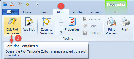

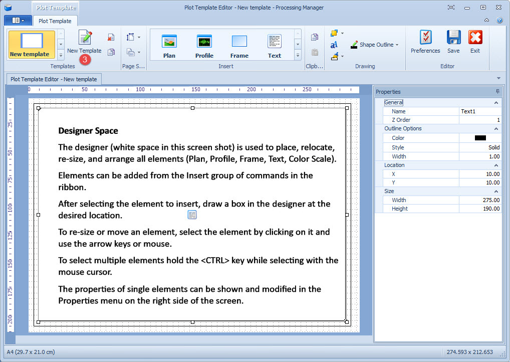

The available command groups in the Plot Template Editor program are:
|
Group |
Commands |
|---|---|
|
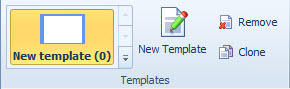
Create a new Template or edit an existing one as listed on the left in the gallery.
|
|
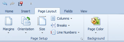
Set the Paper Size and Orientation of the Plot Template.
|
|
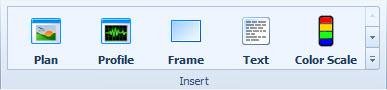
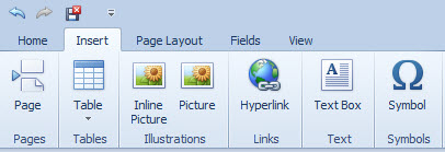
All elements available to insert into the plot are found in the Insert group.
|

|
Items inside the template can be copied and pasted to make ensure they get the same dimensions. |
|
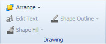
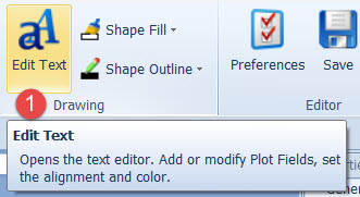
Change the drawing order, color and style of the selected objects in the Drawing group or Edit Text, change the fonts or adjust the text size. |
|
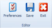
Use the Editor group to set up how the designed space should look and behave. Save or Exit the Plot Template Editor. |
A Plot Template can also be made from the File ribbon tab. Click on New and then on Plot Template.
Return to: top of page.
Edit Plot Layout Settings
If Custom, set the Conversion Factor which is always shown relative to meters.
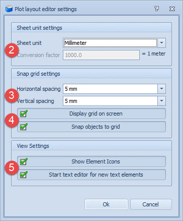
Set a value for the interval between the horizontal and vertical grid lines.

Display the grid and use the grid spacing for accurate grid snapping.

These are displayed in the center of frames to show which type of element they are.
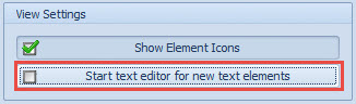
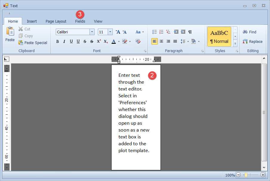
Tick Start Text Editor for New Text Elements to automatically start the Text Editor when a new text box is added to the template.
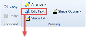
If not ticked, text can be added to the box later using the Edit Text button in the ribbon.
Return to: top of page.
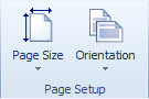
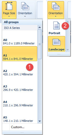
Page Setup
The Page Setup group is used to set the Paper Size and Orientation for the Plot Template Editor.
The size and orientation can still be changed during the creation of the Plot Template.
Select one of the predefined sizes or select a Custom paper size from the drop down menu.
Return to: top of page..
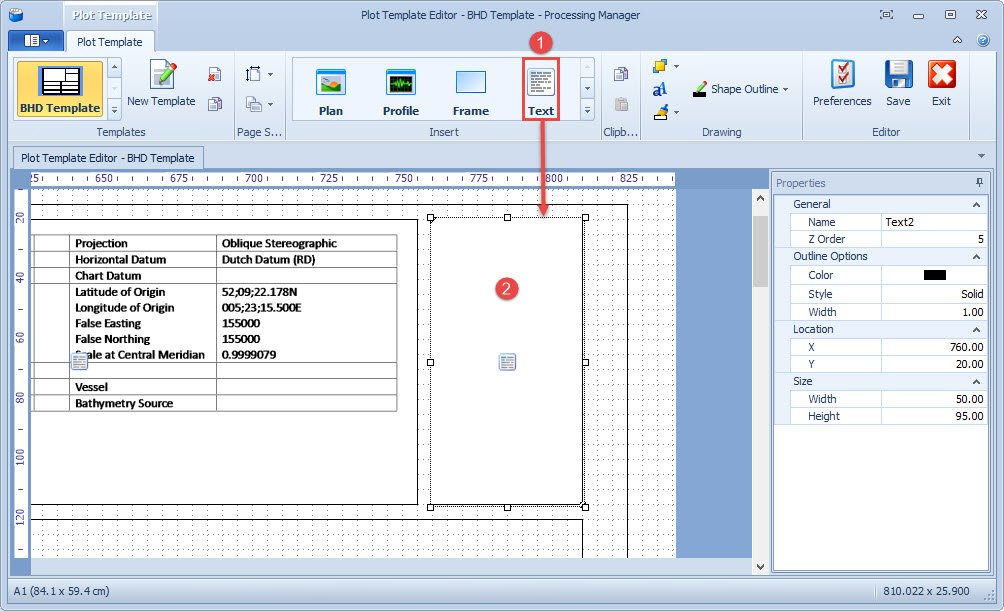
Insert Plot Elements
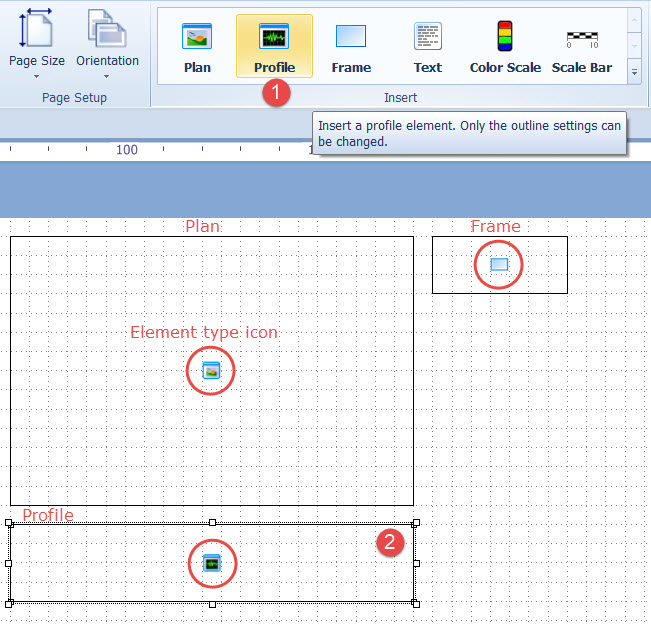
All available elements to insert into the plot are found in the Insert group
Each element has a tool tip : a short description of its function. Use these tool tips to decide which elements to insert into the template.
The icon centered on the plotted frame indicates the type of element.
Size and location of any element can be changed by dragging the handles.
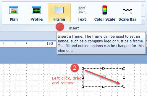
Frame
Frame boxes can be used to outline the entire plot sheet, legends, and other elements.
The fill and outline settings can be changed for this element.
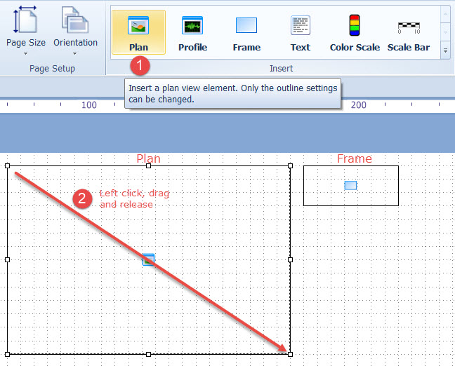
Plan Element
The Plan box contains the top view of the data, i.e. displays a 2D plan view of all or part of the PM Project Window.
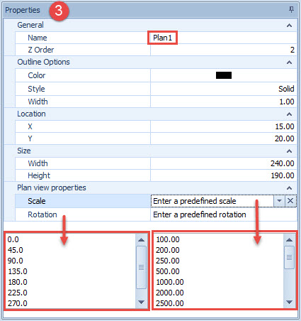
When the predefined Scale and Rotation are set, all plots made with this template will always use the same scale and orientation.
To set a Predefined Scale and/or Rotation select one from the pull down menu, or start typing.
To reset to automatic, empty the value or click on the small delete button in the edit box.
Selecting a frame with the mouse pointer and right-clicking leads to the shortcut menu.
Here the frame settings can be changed, including the frame type, i.e. convert a Plan frame to a Text or Profile frame.
When a frame type has been changed, the name needs to be adjusted in the Properties box on the right side of the screen.
Return to: top of page.
Profile Element
Draw a frame which will contain the Profile of the selected line.
Only the outline settings can be changed.
The actual profile to be drawn can be selected in the Add Plot menu.
The frame will contain the profile of the selected line. Only the outline settings can be changed.
The actual profile to be drawn can be selected in the Add Plot menu.
Text Element
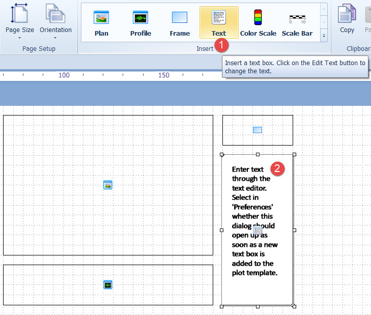
Click on the Edit Text button to change the text or to add Plot Fields.
Color Scale and Scale Bar
From the Insert group add: 

Clipboard
Click on a frame and press Copy in order to Paste another frame exactly like it in another location.
Return to: top of page.
Edit Text
The Text Editor employs rich text as source and can be used to add formatted text, images, tables and fields.
The Editor always shows a document which has the same size as the selected text element.
Text Editor
When adding a new text element, the Text Editor can be started in one of two ways:
-
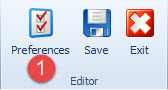
In the Plot Template Editor, click on the Preferences

-
When the Start Text Editor for New Text Elements check box is NOT enabled, open the Text Editor by clicking on the Edit Text

The Text Editor uses rich text as source and can be used to add formatted text, images, tables and fields.
The Editor always shows a document which has the same size as the selected text element.
....use the Edit Text button to add and edit text to the text box.
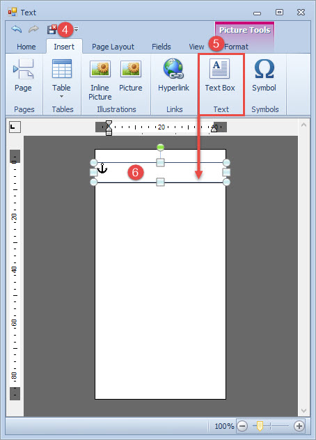
Use the tools in the Text ribbon to design the content and layout of the text box.
Return to: top of page.
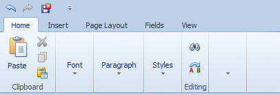
Edit Text Ribbon
|
Tab |
Ribbon |
Description |
|---|---|---|
|
Home |
|
Has all options for changing fonts and text alignments. |
|
Insert |
|
New tables, illustrations and text can be added to the document. When a picture or tab is selected in the document, additional design tabs become available. |
|
Page Layout |
|
Mainly used to quickly change the margins or number of columns in the text element. |
|
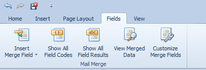
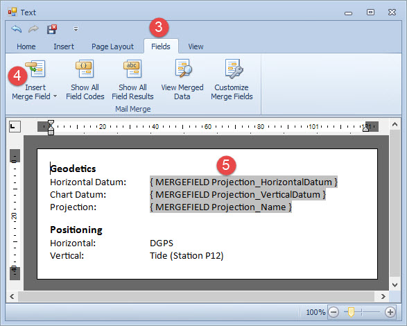
Fields |
|
Used to add merge fields to the document. Merge fields are used as placeholders for real data values, such as a date or project name. A preview of the real data, instead of the place holders can be shown by clicking the View Merged Data button. |
|
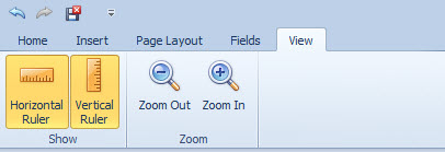
View |
|
The rulers can be enabled. Enlarge the text editing area for better visibility while editing, which can also be done from the status bar or by using <Ctrl> + mouse-wheel. |
Return to: top of page.
Insert Merge Field
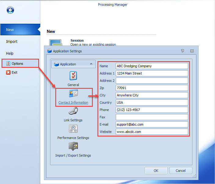
Many text fields can be automatically filled by drawing values from parameters defined in the template database and from the Company Information entered under the File tab.
When the parameter does not exist there are 20 custom fields to use.
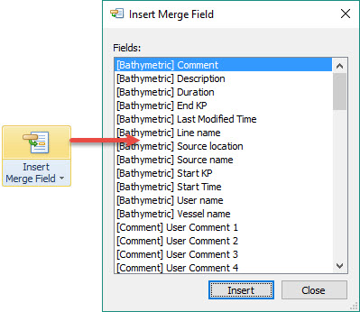
This is used to add Merge Fields to the document. Merge fields are used as placeholders for real data values, such as a date, project name, datums, etc..
|
Clicking on the icon opens the Insert Merge Field dialog in which all the fields available are listed. |
|
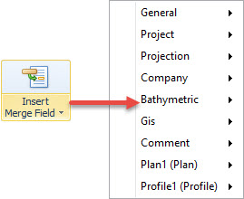
Clicking on the text opens the a list of categorized merge fields. |
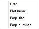
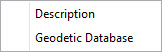
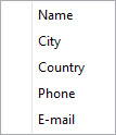
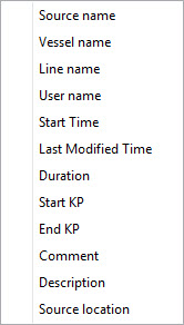
These are the categorized merge fields:
|
General |
Project |
Projection |
Company |
Bathymetric |
|---|---|---|---|---|
|
|
|
|
|
|
GIS |
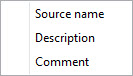
Comment |
Plan |
Profile (Part I) |
Profile (Part II) |
|
|
|
|
|
Return to: top of page.
Customize Merge Fields
The field names and available fields can be modified using the Customize Merge Fields dialog. (See screen capture below.)
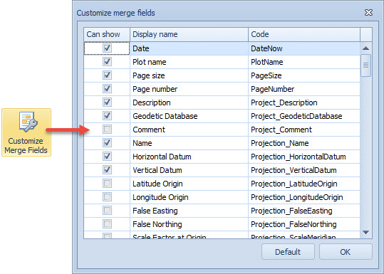
Some merge fields, such as date and time, can be formatted in various ways. See Advanced Field Formatting for more information.
Most fields are automatically filled in, except for the Company related fields. These fields can be modified in the File tab's Contact Information.
Example:
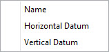
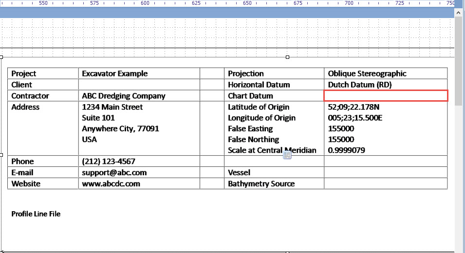
Here a number of Merge Fields have been added in a table. All parameter values are drawn from the Geodetics section of the template database.
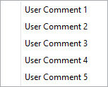
However we want to substitute a different name for the Vertical Datum. A User Comment is employed.
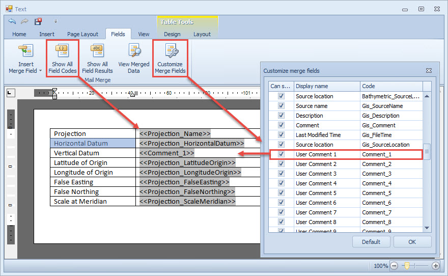
View Merged Data shows the values extracted from the template database. Vertical Datum has no value yet assigned to Comment 1.
Save and Exit.
This field is blank in the Plot Template Editor. Values for Fields that require input are filled in under Plot Data Preferences.
Return to: top of page.
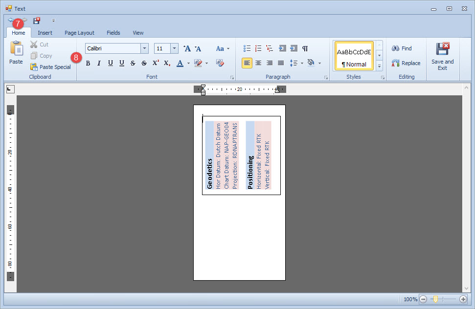
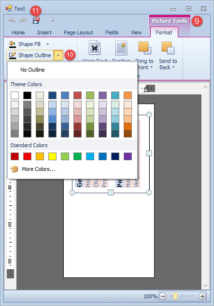
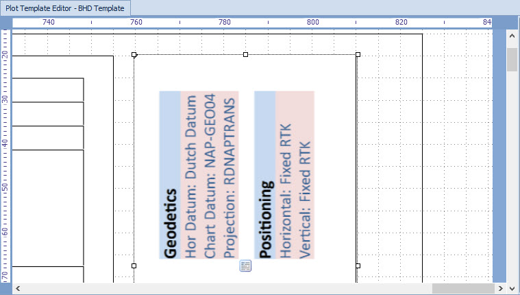
Rotate Text
If you prefer a vertical legend there is a way to rotate a text box. For example in the image below you prefer to have the Geodetics and Positioning information reading vertically rather than horizontally.

Rotate the new text box using the green rotation handle.


Return to: top of page.
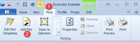
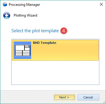
Setting up the Plot
Adding a Plan Box to the Plot
Use this option to add a previously created Plot Template to the Plots gallery for plotting purposes.
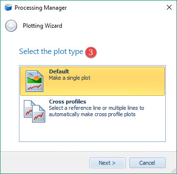
|
Plot type |
|
|---|---|
|
Default |
Creates an empty sheet in which the user can add his own elements to plot. |
|
Cross profiles |
Generates a plot for multiple cross profiles.
|
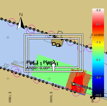
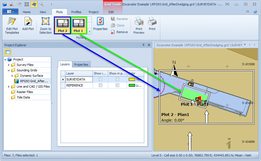
This action puts a plot box in the Project Window with a best-fit scale.
In the example below, there are two plot boxes added because the Plot Template includes two plan boxes.
The X:Y ratio is the same as that established for the Plot element in the Plot Template Editor.
Make sure that the Sounding Grid layers which are to be presented in the plot Plan box are switched on under the Project Explorer's Layers tab.
Return to: top of page.
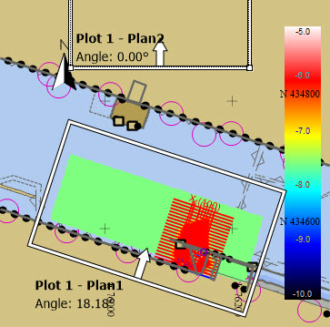
Adjusting The Plot Plan View Graphically.
Click on the edge of the plot and drag the dotted frame to the correct place; click on the handles in the corners to change the shape.
The plot can be rotated by placing the mouse cursor over the green rotation handle, holding the left mouse button and dragging the frame.
Plot Data Preferences
Use this dialog to enter a number of settings before you start plotting.
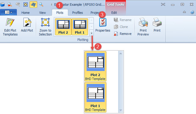
By switching on multiple plots, they will appear together in the Properties dialog. This way they can be reviewed and edited in one session instead of opening a Properties dialog for each one separately.
Plan View Element Settings
|
The gallery shows all available plots in the active project.
|

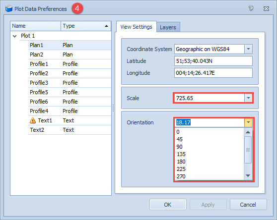
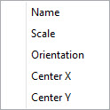
Choose either a geographical or grid graticule and modify Scale and Orientation, choosing from the predefined values in the drop down lists or entering your own values.
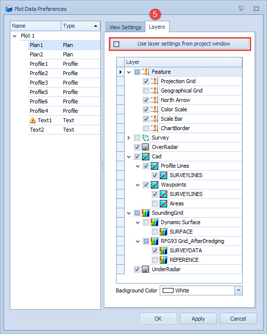
Either select the layers you want presented in the Plan box here in the Data Preferences dialog, or tick the Use Layer Settings from Project Window check box. In the latter case make sure the correct layers are active.
Press Apply to implement new settings without leaving the dialog box.
Return to: top of page.
Profile View Element Settings
Click on each Profile line separately to be able to edit the settings.
Make sure that the Sounding Grid layers which are to be presented in the plot Profile boxes are switched on under the Project Explorer's Layers tab.
When applicable: By selecting all profiles at the same time, the same settings will be applied to all of them. This will result in the Line Selection tab not appearing.
Line Selection
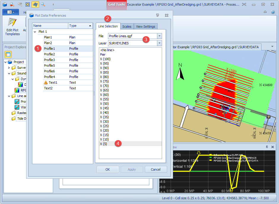
Repeat for the other Profile boxes.
When applicable: By selecting all profiles at the same time, the same settings are applied to all of them.
This results in the Line Selection tab not appearing.
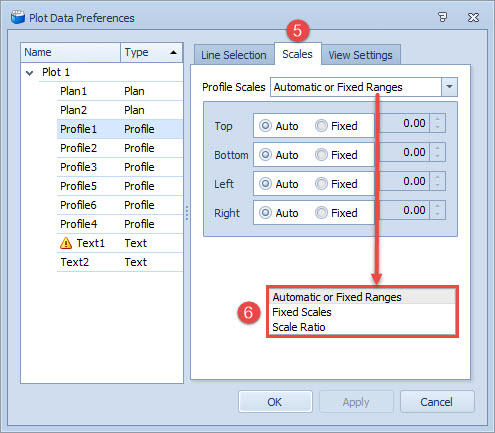
Scales
|
Scales
|
|
|---|---|
|
Automatic or Fixed Ranges |
Automatic - Automatically selects the highest and lowest values in the profile and makes the scales fit.
|
|
Fixed Scales |
Horizontal and Vertical scales can be entered manually. |
|
Scale Ratio |
Enter the Horizontal scale and the Ratio for the vertical scale.
|
After each new setting Apply can be pressed to save the changes.
View Settings
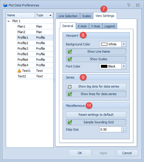
Also choose whether profile data points should come from a sounding grid and, if so, what the sampling Step Size should be.
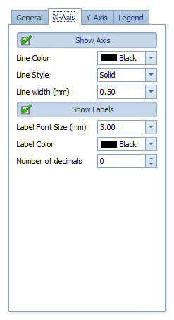
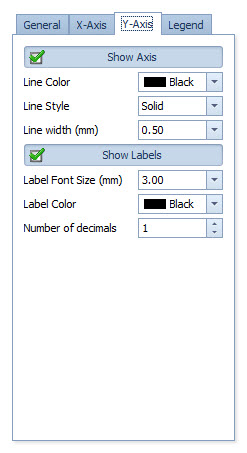
|
X Axis |
Y Axis |
Legend |
|---|---|---|
|
|
|
|
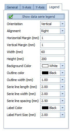
Legend |
|
|---|---|
|
Show data series legend |
Show a small legend box inside the Profile plot. |
|
Orientation |
Draw the lines of the legend in a vertical row or in a horizontal row. (The horizontal box will need adjusting to show all lines.) |
|
Alignment |
Select a position for the legend. |
|
Horizontal Margin |
Set the distance which the legend should stay away from the side of the Profile plot window. |
|
Vertical Margin |
Set the distance which the legend should stay away from the top of the Profile plot window. |
|
Width |
Set the width of the legend. |
|
Height |
Set the height of the legend. |
|
Background Color |
Set the background color for the legend. Select a color from the menu. |
|
Outline color |
Set the color for the outline of the legend. Select a color from the menu. |
|
Outline width |
Set the width of the legend outline. |
|
Series line length |
Set the length of the legend lines. These are the colored lines in front of the survey line names. |
|
Series line width |
Set the width of the legend lines. |
|
Series line spacing |
Set the line spacing for the lines inside the legend. |
|
Label Color |
Select a color for the text in the legend. |
|
Label Font Size |
Set a size with the scroll buttons or enter one manually. |
Return to: top of page.
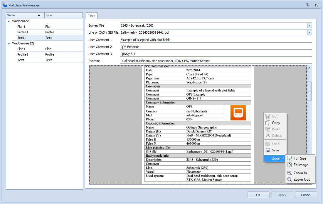
Text View Element Settings
Highlight a text box on the left side to see an overview of the text element to be plotted.
To zoom in click with the right mouse button in the Preview and select the Zoom action.
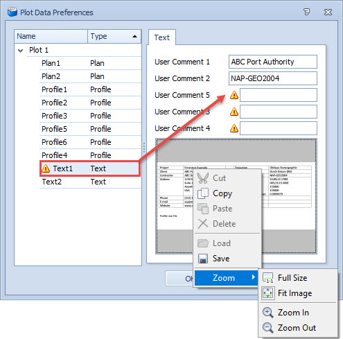
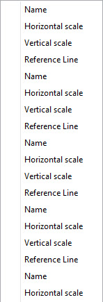
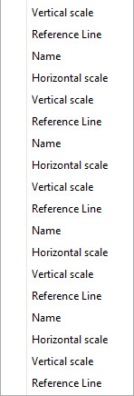
In the image above you can see that User Comments 1-2 are filled in with 3-5 still showing the need values entered ( 
These values are used in the final plot, as shown in the Print Preview window below.
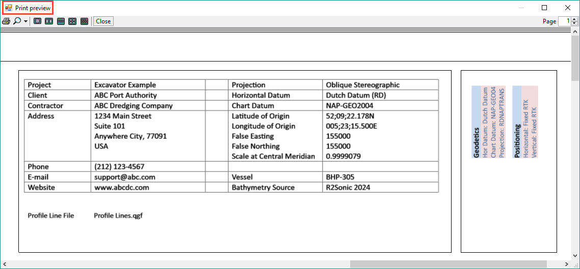
In the next example six fields require data selection or entry:
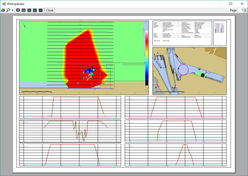
Printing
Use Print Preview button to review how the plot will look in final form.
Use the Print button to send the plot to a printer.
Return to: top of page.
Return to: BHD - Plotting.
Return to: BHD - Dredging Results.