
Below, you will find for each supported format more info
ASCII
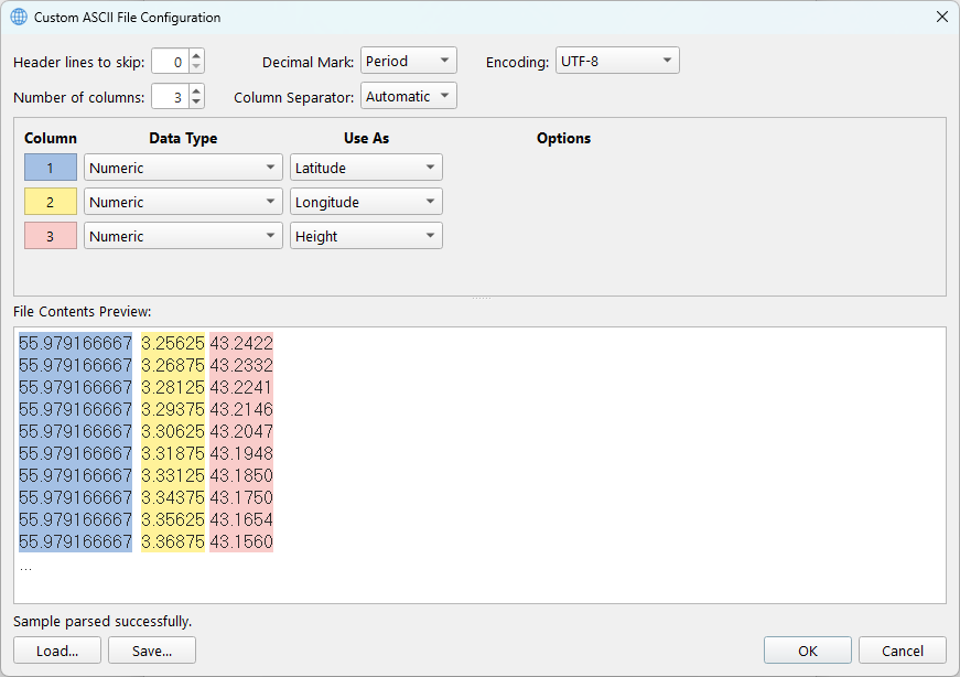
The ASCII file format is a versatile file format that accommodates a broad range of file structures.
Coordinates may be represented in either latitude and longitude or in easting and northing.
Each row must include a coordinate and a height.
For detailed information about the dialog, see the ASCII file configuration dialog.
All coordinates must maintain a consistent spacing; otherwise, a message will indicate that conversion is not possible.
ARC ASCII
The ARC ASCII file format is an Esri grid, a raster GIS file format developed by Esri. This format is also referred to as the Arc/Info ASCII grid.
It features a header structure that specifies the grid's reference, followed by the values presented in the order they appear (left to right and top to bottom).
ncols 4
nrows 6
xllcorner 0.0
yllcorner 0.0
cellsize 50.0
nodata_value -9999
-9999 -9999 5 2
-9999 20 100 36
3 8 35 10
32 42 50 6
88 75 27 9
13 5 1 -9999
Where:
-
ncols is the number of columns (represented as integers)
-
nrows is the number of rows (represented as integers)
-
The lower-left corner refers to a cell corner, not to a data point
-
xllcorner and yllcorner are the western (left) X coordinate and southern (bottom) Y coordinates (represented as real numbers with an optional decimal point). An alternative is the use of xllcenter and yllcenter.
-
cellsize is the length of one side of a square cell in degrees. Alternatively, it could contain xdim and ydim.
-
xdim is the length along the horizontal side of a cell in degrees.
-
ydim is the length along the vertical side of a cell in degrees.
-
nodata_value is the value that is regarded as "missing" or "not applicable."
The remainder of the file lists the raster Z values for each cell, starting at the upper-left corner cell. The Z values are always reported for the center of each grid cell. These real numbers (with an optional decimal point, if needed) are delimited using a single space character.
Based on the header values, if the resulting minimum and maximum X and Y coordinates remain within the latitude and longitude boundaries, the file is considered geographical; otherwise, it will be regarded as projected.
ISG
The International Service for the Geoid has developed a format for providing models. This design adheres to format version 2.0 and extracts all necessary information from the file header. Below is an example for detailed information: https://www.isgeoid.polimi.it/Geoid/format_specs.html
begin_of_head ================================================
model name : EXAMPLE
model year : 2020
model type : gravimetric
data type : geoid
data units : meters
data format : grid
data ordering : N-to-S, W-to-E
ref ellipsoid : GRS80
ref frame : ITRF2014
height datum : ---
tide system : mean-tide
coord type : geodetic
coord units : dms
map projection : ---
EPSG code : 7912
lat min = 39°50'00"
lat max = 41°10'00"
lon min = 119°50'00"
lon max = 121°50'00"
delta lat = 0°20'00"
delta lon = 0°20'00"
nrows = 4
ncols = 6
nodata = -9999.0000
creation date = 31/05/2020
ISG format = 2.0
end_of_head ==================================================
 30.1234 31.2222 32.3456 33.4444 34.5678 36.6666
 41.1111 42.2345 43.3333 44.4567 45.5555 46.6789
 51.4321 52.9753 53.6543 54.8642 -9999.0000 -9999.0000
 61.9999 62.8888 63.7777 64.6666 -9999.0000 -9999.0000
Trimble GGF
The GGF format is specific to Trimble software and is proprietary. Due to the complexity of height storage in the file and the lack of diverse example files, a warning message will appear if the loaded file contains an untested flag. In such cases, we recommend additional manual validation of the converted model.