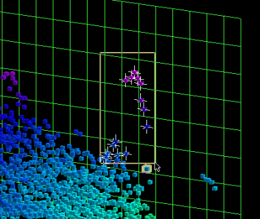
3DEditor Main Visualization Window
The Main Visualization Window of the 3DEditor displays the soundings from the PFM file that are being edited. The unedited soundings will be displayed as a set of small cubes that are colored by height. To navigate around the display, the same widget-based interface as Fledermaus is used.
Outside of the soundings shown in the Main Visualization Window is a green, 3-dimensional grid that represents the bounds of the loaded data. In UTM, the Eastings and Northings are displayed along the bottom of the data and in Geographic coordinates, the longitude and latitude are shown. The grid spacing along the bottom of the grid indicates the cell spacing of the file. Determining which soundings contribute to which cell can be examined by looking straight down (plan view). The different height values are shown in meters along the vertical axis.
When the mouse is moved, the sounding located closest to the mouse cursor becomes highlighted and information pertaining to it is displayed at the top of the window. The displayed information includes the record, sub-record, line, file, UTM coordinate, and Geographic coordinate. As well, the number of selected soundings is displayed at the top left of the interface. To prevent the sounding information from being constantly updated as the mouse is moving, double-click the left mouse button to lock the currently highlighted sounding. Double-clicking a second time will unlock the sounding.
The 3DEditor contains five modes: Explore, Select, Area Select, Record Select, and Measure. Each one of these modes can be activated from the Control Bar. Switching into Select or Area Select mode, and then clicking the left mouse button selects points. Once selected, a white cross will appear over a sounding to indicate that it has been selected. Note that the title bar displays the total number of points being viewed, and the box at the top left of the screen displays the number of selected soundings. Record Select mode allows selecting and deselecting whole records at a time (i.e. one entire ping). To deselect a set of points, hold down the Shift key while clicking or dragging with the left mouse button. The Mouse Buttons in the 3D Editor table describes the usage of the three mouse buttons in the available modes. The Explore mode is set as the default. The figure Selecting Soundings using Select Mode shows a selected set of soundings after dragging in Select mode.
To measure the distance between two soundings, switch into Measure mode and click the left mouse button on the first sounding to measure from. Moving the mouse to another sounding in the display will cause a line to be drawn between the soundings in the Main Visualization Area and the distance in meters will be displayed in the upper left corner of the interface. The compass angle and the angle of declination between the soundings will also be displayed in the upper left corner. Click the left mouse button again to start another measurement.
Table - Mouse Buttons in the 3D Editor
Mouse Buttons | ||||
Left | Shift + Left | Middle | Right | |
Modes | ||||
Explore | Pick and drag surface to rotate about either horizontal or vertical axis. | Animated move to selected position, and zoom in if mouse moved up, or zoom out if mouse moved down. | Show right-click menu | |
Select | Single click to select the highlighted point; drag to select a box shaped area. | Single click to deselect the highlighted point; drag to deselect a box shaped area. | Same as Explore | Same as Explore |
Area Select | Single click to select the highlighted point; drag to select an irregular area. | Single click to deselect the highlighted point; drag to deselect an irregular area. | Same as Explore | Same as Explore |
Record Select | Single click to select the record (swath) that the highlighted point is a part of; drag to select all records that contain a point in the box. | Single click to deselect the record (swath) that the highlighted point is a part of; drag to deselect all records that contain a point in the box. | Same as Explore | Same as Explore |
Measure | Single click to start measurement. Single click again to stop measurement. | Same as Explore | Same as Explore |

Selecting Soundings using Select Mode
Depending upon the flags set for a sounding, it will appear as a different symbol in the Main Visualization Window. How the different soundings appear can be controlled using the Soundings Panel in the Editor Panels or the Control Bar. The Types of soundings in the 3D editor table lists all sounding classes in order of priority and lists the default display attributes. See the Soundings Panel for more information about changing the sounding display.
Table - Types of soundings in the 3D editor
Sounding Type | Default Display Attributes |
Deleted | Red Diamond |
Feature | White Cylinder |
Plotted | Outlined box colored by depth |
Suspect | Yellow Diamond |
Normal | Box colored by depth |
Note that some formats now support NBR (i.e. no bottom return) soundings. These soundings have an X and Y position, but no depth. If the PFM contains a custom flag named "NBR", soundings with that flag set will be drawn as an outline shape (usually an outline red diamond) at the base of the 3DEditor.
