

Fledermaus Scene Toolbar
Fledermaus Scene Toolbar
The scene toolbar in Fledermaus deals with Scene data interaction modes, zoom buttons, selection modes, profiles, measuring and scene component modes
Data Interaction Modes
2D View
While in 2D View, Plan View, simply Left-Click and drag to pan the scene. Moving the mouse-wheel will zoom in or out of the scene. You can also pan by using the right and lower scroll widget. Use the left scroll widget to zoom.
3D Turntable View
While in 3D Turntable View, simply Left-Click and drag in the horizontal direction to rotate the scene around the current center point. Left-Click and drag in the vertical direction to tilt the scene. Center-Click on a point in the scene to change the current point of rotation. You can also use right scroll bar to move the scene up or down, the bottom scroll bar to move the scene left or right, and the left scroll bar to zoom in and out of the scene. While in this mode, you can also interact with the Navigation Widget to navigation in the scene.
3D Flight View
While in 3D Flight View you can use the keyboard and/or a supplemental navigation device such as the Patriot Bat, a SpaceNavigator, or a VIVE controller to explore the 3D world. The AWSD keys move you left, forward, backward, and right respectively from your current view point. The Q and E keys move your camera up and down in the z-axis. If you left click and drag the mouse you can control the viewpoint while applying other key combinations. When using a supplemental flight device enter flight mode by holding the trigger button and translate and rotate to control the camera velocities when moving through the scene.
Zoom Buttons
Zoom to Scene
Clicking on the Zoom to Scene button returns to the default camera position. The default camera view is normally looking down at the data at about 45 degrees; however, this can be changed in the General Preferences if an alternate view is desired. If the data objects are lost from view in the 3D scene simply click this button to return to the default viewpoint.
Zoom to Object
Zoom to object (Z-key) button will move the camera so that you are viewing the currently active data object.
Zoom to KP
Zoom to the KP found in either the last selected route from a project or from the selected route object. The Route object must have KP values generated. See the Route page for more information
Cursor Mode Buttons
 Explore.
This is the primary navigation mode of the 4D scene. If you are in any other cursor mode, simply hold down the Shift key to allow standard explore mode navigation behavior. When in explore mode, status information about the objects under the cursor will be displayed in the Status Bar. If you are in Plan View, use a Left-Click-Drag to pan around the scene. Use the mouse wheel to zoom in and out of the scene. Alternatively, you can Center-Click-Drag to zoom in and out of the scene. If you are in Turntable View, a Left-Click-Drag horizontally will spin the scene about a central point as if the scene was on, you guessed it, a turntable. If you drag vertically, it will tilt the table toward or away from your viewpoint. To change the center of rotation, Center-Click a different location in the scene. This also works when in Plan View.
 Rectangular Selection
This mode allows for rectangular area selections within the scene on a surface. This area can be used to enter the 3D Editor. Once the rectangle has been drawn on the surface, it can be rotated or reshaped using the drag handles that appear on all sides and corners of the widget. If you Left-Click and drag one of the corner handles, it will resize the rectangle width and height. Left-Click and drag on one of the side handles, it will resize the rectangle in the associated axis. Left-Click and drag on the center handle rotates the selection rectangle. Left-Click and drag inside the rectangle but not over one of the handles allows you to move the rectangle over a surface. An example of this selection mode while Slice Editing is shown below.
To easily move the Rectangular Selection, use the W and S keys to move forward and backwards along the direction of the arrow. Use the A and D keys to move left and right, perpendicular to the arrow. Use the Q and E keys to rotate the selection +/- 15 degrees.
 Polygonal Selection
Left-Click a series of points on a series to define a selection polygon. You must select on the initial point to close the polygon.
Hitting the ESC key at any point during polygon selection will remove the last polygon point created.
 Free Hand Selection
Left-Click and drag a shape to define a selection area. When you release the left mouse button, the selection area will be closed automatically.
 Clear Selection
Clicking this Icon will unselect any current selection area.
 Profile Tool
Left-Click a series of line segments on a surface to see the depth profile in the Profile Window. Right-Click to end the profile.
Alternatively, you can Ctrl+Left-Click and drag to make a quick, single segment profile without having to activate the profile tool first.
An example of a multi-segment profile with a cross profile is shown below.
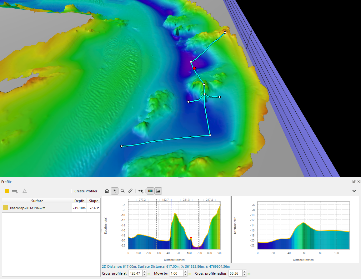
Profile Tool
Once created, the profile can be edited in the scene. The mouse cursor will change to one of the following cursors to indicate which action will take place when left-clicking:
 Picking (Cross cursor)
This cursor appears when defining the profile line as described above, or when the mouse is away from the profile line. While this cursor is displayed, the mouse is used to pick the control points of the profile line. Left-clicking on a surface picks the clicked location as a control point. If the line is already defined, left-clicking will prompt you to delete the current line and start a new line. Right-click is used to finish the line.
 Line Translation (Hand cursor)
This cursor appears when the mouse is near or on top of the profile line, but not on top of a control point. While this cursor is displayed, left-clicking and dragging will move the entire profile line around the scene.
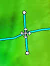
 Point Translation (Four arrow cursor)
This mode is activated when the mouse is on top of a control point. While this cursor is displayed, left-clicking and dragging will move the control point under the mouse around the scene.
When cross profiling is turned on in the profile panel, some additional controls become available on the profile tool in the scene. Note that while the basic profile tool is available in Fledermaus Viewer, the cross profiling capabilities are not.
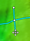
Cross-profile position
Left-clicking and dragging the control point at the center of the cross-profile line where it intersects the main profile line allows you to move the cross-profile line along the main profile line. This can also be done by changing the "Cross-profile at” value in the profile panel.
Cross-profile radius
Left-clicking and dragging either of the control points at the ends of the cross-profile line will allow you to adjust the radius, or distance from the main line, of the cross-profile. This can also be done by changing the “Cross-profile radius” value in the profile panel.
If you left click when not on a control point where the normal cross hair cursor is shown you can start a new profile. A dialog will appear asking you to confirm that you meant to start a new profile and one can proceed or not. If you are editing a profile path that comes from a profiler object the ability to create a new profile is disabled.
Additional operations can be accessed via context menu by Right-clicking after the profile has been completed (after right-clicking to stop adding points to the line). These operations include:
-
Create Line From Profile: Creates a new Lines object from the profile path.
.png?cb=08adaaa66aa01b8f5ba15ed032ca03c7) Measuring Tool
Measuring Tool
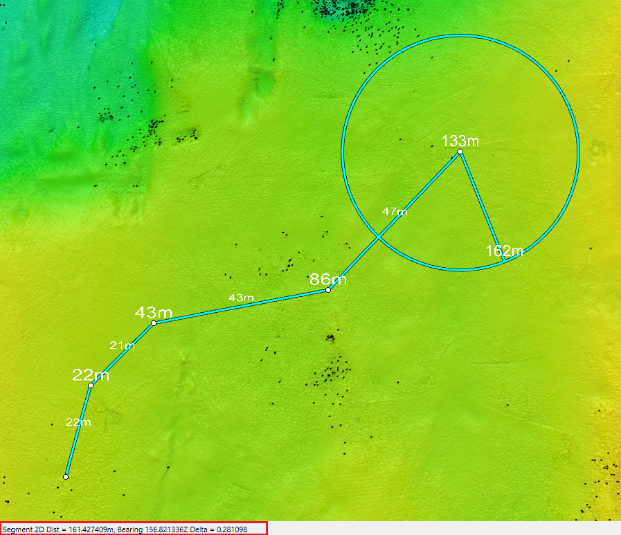
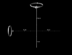
Left-Click a series of line segments on a surface to see total distance, line segment distance and line segment bearing. You will see the last segment 2D distance, Bearing, and Z Delta displayed in the Status Bar. As you move to a new location, a range circle will be drawn so that you can see all parts of the survey within the particular range. An example of a completed multi-segment measurement is shown below.
Hitting the ESC key at any point during line segment creation will return you to the Explore mode.
Measuring Mode
Note that the measure tool will attempt to show the distance with at least two significant digits, if possible, from the last point created. See the following examples:
(a) 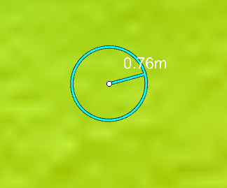
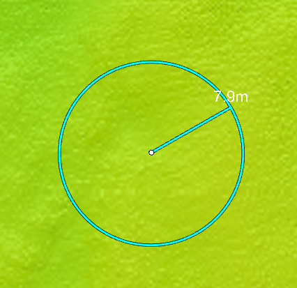
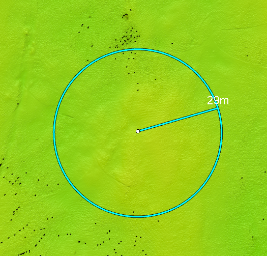
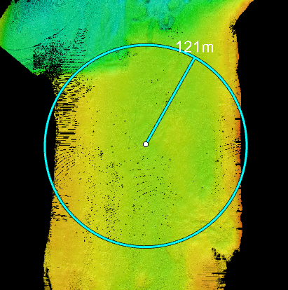
Measuring Mode Precision: Showing minimum of two digits in (a) centimeters (b) tens of centimeters (c) meters
You can increase or decrease the size of the text on the measuring tool using Shift+= and Shift+- respectively. These keyboard shortcuts can be changed in the Configure Shortcuts menu by rebinding the Increase Tool Text Scale and Decrease Tool Text Scale actions.
Route Planning Tool
Left-Click to create line segments, when a corner is formed the tool will automatically create a curve in its place. Right-Click to end the route.
An example of a finished route is shown below.
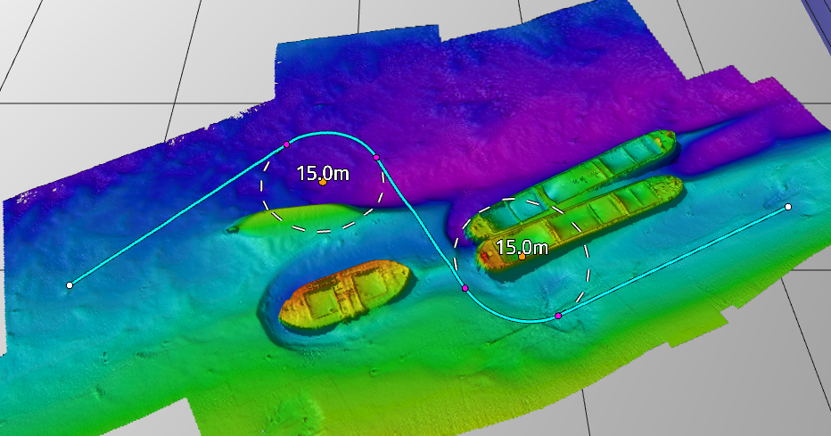
Route Planning Tool in use
Once created, there are a few ways to modify the route.
-
Start/End points: The white points at the start and end of the route can be moved by Left-clicking and dragging them around. Curves tangential to the dragged point will automatically adjust themselves as these points are moved.
-
Tangent points: The magenta points which mark the start and end of each curved segment can also be moved by Left-clicking and dragging them. Moving either of the two tangent points on a curve will move the entire curve segment without changing its radius. Again, adjacent curves will be adjusted automatically as you move the point.
-
Center points: The orange point at the center of a curve is used to adjust the radius of the curve. Left-clicking and dragging on the point will not move it, instead the radius will increase if the mouse is moved up or to the right, or decrease if the mouse is moved down or to the left.
Note that you may not always be able to drag a point. The tool prevents you from dragging points into a position which would result in an invalid route. If you want to drag a point somewhere and cannot, try adjusting nearby curves or the start and end points first.
Curves created while defining the line will try to set the radius to the default value, which can be changed in the preferences under the General tab. If a curve cannot use the default radius without invalidating the route (for example, because the angle of the turn is too sharp) then it will automatically reduce the radius to the largest value that will fit.
Additional operations can be accessed via context menu by Right-clicking after the route has been completed (after right-clicking to stop adding points to the route). These operations include:
-
Create pipe from route: Creates a new Dynamic Pipe object from the route. Before creating you can choose the sample interval and pipe radius to change the resolution and size of the cable/pipe.
-
Export to ASCII: Samples points at the sample interval from the start of the route to the end, and saves the XYZ (or just XY if selected) coordinates to a new plain text file.
-
Export to Lines: Creates a new Lines object from the route. This is equivalent to exporting the route to ASCII and then importing that text file as lines.
-
Export to PLF: Saves the route parameters to a PLF formatted text file which can be used to rebuild the profile in supporting software.

Add Space-Time Notes
Left click to add Space-Time Notes. This mode will stay active until another mode is selected or by clicking on this mode button again to return to explore mode. Press and hold one of the shift keys to explore while in this mode.
Scene Component Buttons
 Color Map
Show/Hide the color map overlay for the selected surface.
Render Bounding Box
The Bounding Coords button will show or hide the Root Node's bounding box and associated coordinate labels. Note that coordinate labels only appear after data has been loaded.
Render Widgets
Navigation Widget
Return to Fledermaus Toolbars.