XSens Motion Tracker MTi (Heading) (Active) - 05
Description
The MTi is a miniature, gyro-enhanced Attitude and Heading Reference System (AHRS), manufactured by XSens Technologies B.V..
Its internal low-power signal processor provides drift-free 3D orientation as well as calibrated 3D acceleration, 3D rate of turn (rate gyro) and 3D earth-magnetic field data.
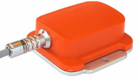
The driver decodes heading and/or motion (pitch, roll, no heave!) from the binary messages. Two versions of the driver are available: an active version and a passive one. The active driver sends certain commands to the sensor, in order to set the required output mode and output settings. The passive one only receives data, and the MTi sensor should therefore be programmed in such a way that it outputs the data in the required output mode and output settings. See Decoding Notes below for the correct settings.
Driver Information
Driver | XSens Motion Tracker MTi | Interface Type | Serial | Driver Class Type | Counted |
|---|---|---|---|---|---|
No | Input / Output | Input | Executable | DrvQPSCounted.exe | |
Related Systems |
| ||||
Related Pages | |||||
Decoding Notes
It is recommended to use the active driver , in order to let the driver set automatically the correct Output Mode and Output Settings.
As soon as the driver is started (on-line) it will send certain commands to the MTi sensor. The first command will be a request for the current Configuration parameters. The output mode and output settings are part of these parameters. If the output mode and output settings are not conform requirements, the driver will send several commands to the MTi sensor to correct this.
In case the sensor does not have the correct settings (e.g. first time use), notice that it may take up to 15 seconds before receiving the first valid roll, pitch and heading data. The next time you go on-line, the data will be decoded almost instantly.
Note that no Quality indicators are decoded; they are simply not part of any message.
If you use the passive driver , it is recommended to program the MTi sensor as follows:
Output Mode | Disable the Temperature data, Auxiliary data and Raw Intertal data messages. |
Output Settings | Disable the Sample Counter (No timestamp). |
Sample Frequency | Set to 10 Hz. |
If the MTi sensor is programmed as stated above, then the passive driver will recognize the datastream immediately, and will decode the roll, pitch and yaw successfully.
If the MTi sensor is programmed to output different messages than specified above, the driver will only recognize the data after receiving a so-called Configuration message from the sensor. You may trigger this configuration message by disconnection the lemo plug of the MTi sensor and connecting it again while on-line. By doing this, a single configuration message will be sent to the driver, and after receiving this the driver will decode the roll, pitch and yaw successfully.
Interfacing Notes
In case of using the active driver, wiring of the interface cable must be bi-directional. If you use the standard delivered USB-serial cable, then all the wiring should be already correct.
In case you are using a serial cable that connects the lemo plug (back-end MTi sensor) to a 25pin or 9pin RS-232 connector, use the following diagram:
DB-25 | COM | or | DB-9 | COM |
|---|---|---|---|---|
Pin 3 | RXD | Pin 2 | RXD | |
Pin 2 | TXD | Pin 3 | TXD | |
Pin 7 | SG | Pin 5 | SG |
Further, an extract from the "MTi and MTx User Manual and Technical Documentation" manual shows the following necessary wiring of the lemo-plug:
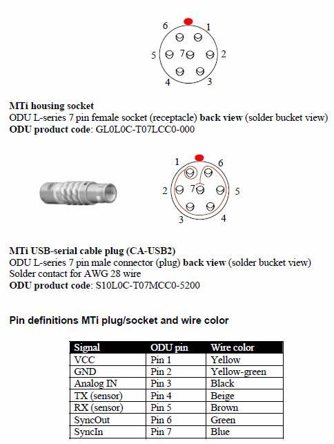
System Configuration
In order to interface the MTi sensor using the USB-Serial cable, you will need to install the USB driver first for the Xsens USB-serial Converter.
Do not connect the USB Cable to your computer yet!
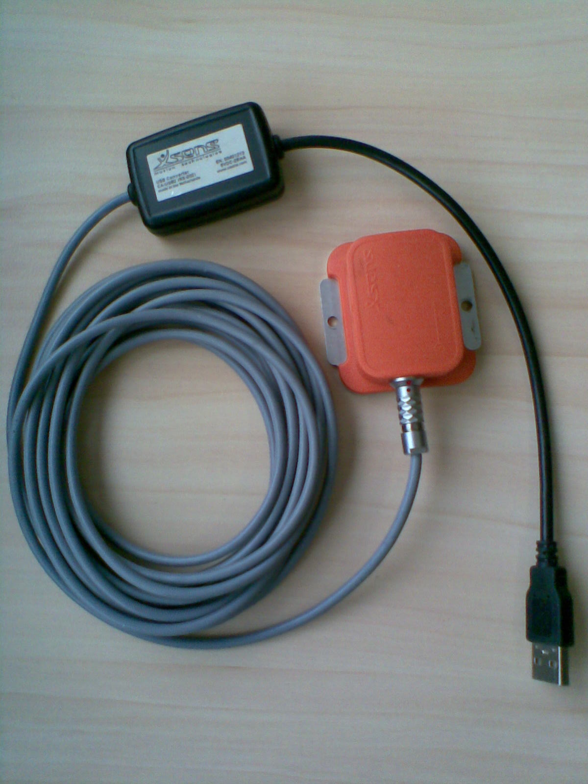
The driver can be installed using the SDK installer or alternatively using the driver which can be found on the Xsens website: www.xsens.com/download/Driver_USB_serial_converter.zip
For the SDK installation follow the following procedure:First install the SDK software that comes with the MTi sensor.
At the end of the installation, there is no need to continue with the MatLab installation. You may cancel that one.Now connect the MTi sensor using the USB-Serial cable to your computer...

and wait until Windows has finished installing the drivers automatically.
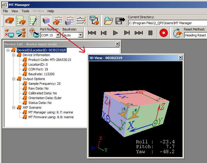
Start the MT Manager to see if it works.
Database Setup
In order to decode a heading from the MTi sensor, add a Gyro and Compass System to your template and select the driver "Motion Tracker MTi (Heading) (Active)".
In order to decode the attitude from the MTi sensor, add a Pitch, Roll and Heave Sensor System to your template and select the driver "XSens Motion Tracker MTi (Roll-Pitch) (Active)".
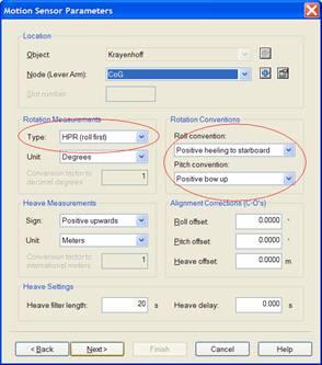
Rotation Measurements:
Type | HPR (Roll first) |
Unit | Degrees |
Rotation Convention and Sign:
Roll | Positive heeling to starboard |
Pitch | Positive bow up |
Heave | N/A (Not Applicable) |
To decode accelerations along and rotation rates around the three axes, add an Acceleration Velocity Sensor system to your database and select the driver XSens Motion Tracker MTi (Acc - RoT) (Active). Then add the following observations: Acceleration and/or Rate-Of-Turn for each axis (X), (Y) and (Z). The unit for the acceleration observation is meters / second squared. For the rate-of-turn, it is degrees / second.
For all a-priori SD values, please consult the MTi Accuracy Specifications.
Online
After installing the SDK you will find the MT Manager in the Xsens program group under Start.
At time of writing this is version 1.5, which comes with SDK v3.1.
Use the MT Manager program to
Check that your MTi sensor is working (see also chapter First Time Users...)
Set the required output settings, in order to communicate with Qinsy:
Make sure your MTi sensor is connected to your computer and start the MT Manager
The program will automatically scan all COMports to find the sensor.
The COMport and baudrate that are found, should be the same as used in your template setup.
Select the third toolbar icon, 'MT Settings', and highlight 'Output Options'Set the settings as described above and as shown in the screenshot below.
Use the 'Write to MT' button to reprogram the sensor with these settings.
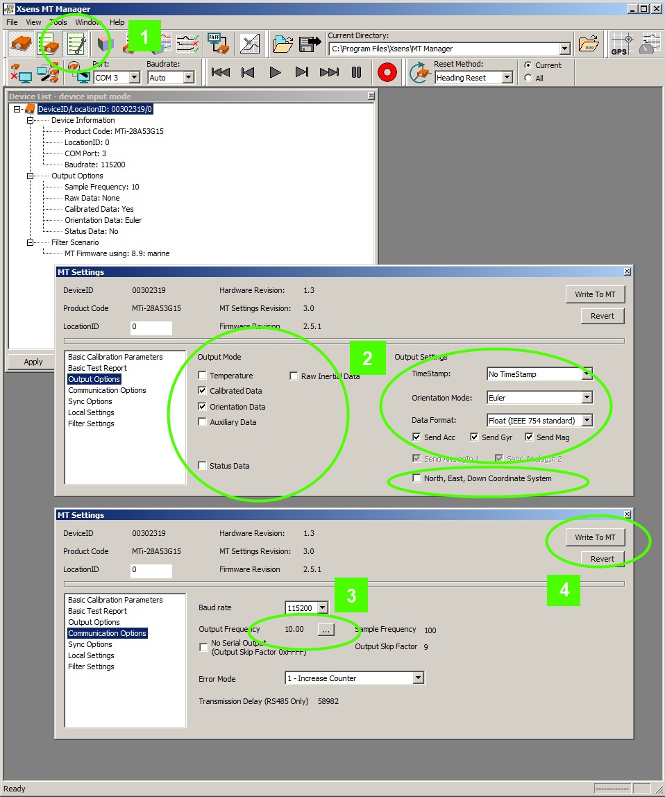
You need to exit in order to go on-line with Qinsy.
Drivers IO Notes
Command line parameter description for "drivers.io" file. Please do not edit this drivers.io file, or only after contacting the QPS support dpt.
Cmdline XSENS_MTI' tells the driver to expect data from a XSens MTi sensor.
Cmdline 'ACTIVE' tells the driver to send commands to the sensor. This makes the setup procedure easier, since some settings are set by the driver and it is not necessary to set them manually.
Additional Information
References: XSens publications:
MT0100P: MTi and MTx User Manual and Technical Documentation
MT0101P: MTi and MTx Low-level Communication Documentation
