
Description
Driver for outputting controlling Seafloor's AutoNav system, used on the Echoboat ASV.
The driver can be used to do the following:
-
Send waypoints
-
Change parameters
-
Control (start/stop/pause) the mission
|
|
|
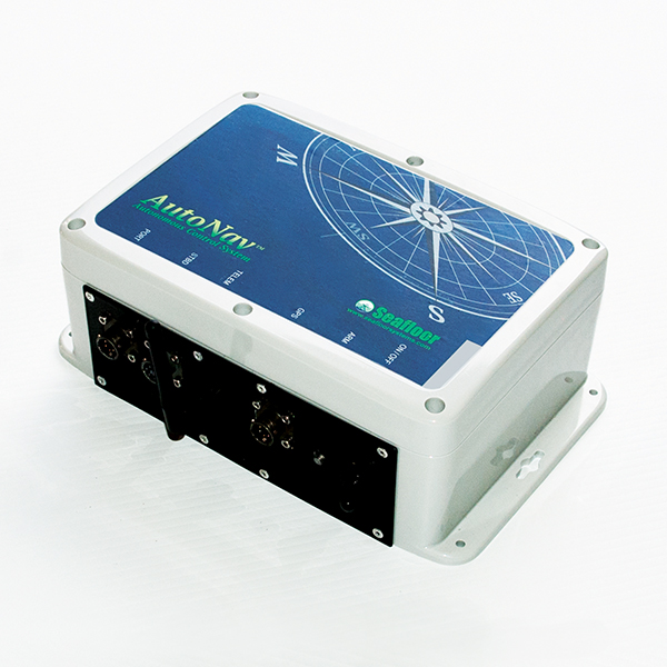
AutoNav control system |
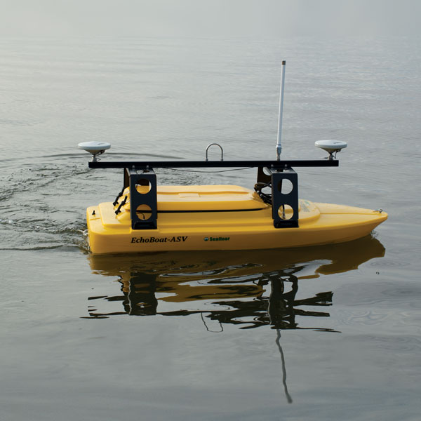
Echoboat-ASV |
|---|
Warning - Qinsy 8.18.x / Qinsy 9.0.x / Qinsy 9.1.0 users
The AutoNav system expects the co-ordinates in the WGS84 co-ordinate system. However, the driver will output the geographical co-ordinates on survey datum by default.
This means that when your survey datum is not WGS84 (or ETRS89), you will have to change the following registry key value from 0 into 1:
HKEY_CURRENT_USER\Software\QPS\Qinsy\8.0\Drivers\DrvOutWaypointsUIMavLink\<SYSTEM NAME>\Settings\WGS84orSD
If this registry key doesn't exist (yet), you should go on-line for the very first time and then go offline again. Now you can change the value from 0 to 1.
Note that you can ignore this warning for Qinsy 9.1.1 and newer versions.
Driver Information
|
Driver |
Waypoints - Seafloor Autonav ASV (MavLink Protocol) |
Interface Type |
Serial |
Driver Class Type |
|
|---|---|---|---|---|---|
|
No |
Input / Output |
Output |
Executable |
DrvOutWaypointsUIMavLink.exe |
|
|
Related Systems |
|||||
|
Related Pages |
|
||||
Interfacing Notes
The AutoNav control system is interfaced through a (virtual) serial port, either by a wireless USB dongle or by directly connecting the AutoNav unit to the USB port.
Use a baud rate of 115200 bps.
Online
The user interface of the driver consists of two parts: one part specifically for sending waypoints and another for AutoNav specific features.
The waypoint part is started automatically. To show the AutoNav specific dialog, click the 'AutoNav' button in the driver.
|
|
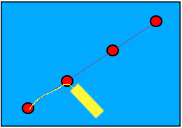
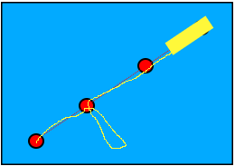
|
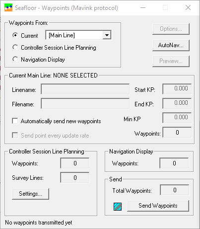
Waypoints dialog |
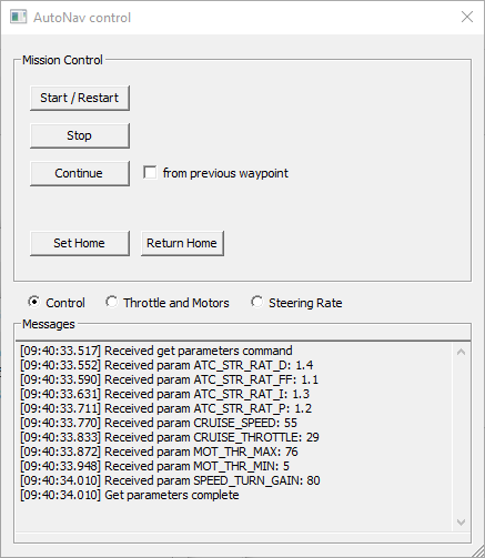
AutoNav specific dialog |
|---|
Waypoints
Waypoint source option
In the driver's dialog the user can select the source of the waypoint track to send:
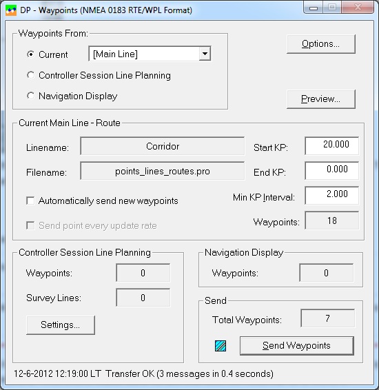
Example of the Waypoint Output Driver's dialog
Waypoints from the Current Mainline
The Current Mainline will be changed automatically when the user selects a new mainline in the Controller's Session Setup . This can be a target (one waypoint), single survey line (two waypoints) or a pipeline (two or more waypoints).
The new Mainline will be sent automatically if "Automatically send new waypoints" is enabled. If the option is disabled, the waypoints will be sent only when the user presses the "Send Waypoints" button.
Waypoints from the Controller's Waypoint Planning
Select Waypoints from the Controller's Waypoint Planning if you want to send more than one single survey line in one go to the DP. Which lines and in what order and with which bearing must be defined in the Controller's Session Setup.
On the first Session Setup Wizard page, select the Planning option. (Note that this option is only available when one of the Waypoint Output drivers exists in the database template).
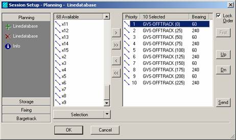
If you are sending parallel survey lines, each one opposite to the previous one, you can enable the calculation of extra waypoints for a smooth turn between the line changes.
Go to Settings... to fill in the Turn Parameters.
Waypoints from the defined track of the Navigation Display
Select Waypoints from the Navigation Display if you want to send the last defined waypoint track of the Navigation Display.
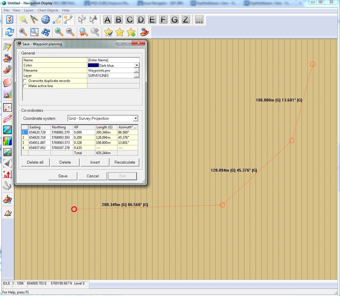
Every time you click and add a new waypoint in the display, the number of Total Waypoints will be incremented in the driver's dialog.
The current waypoint track will be lost when you define a new Waypoint Track, or when you close the Navigation Display.
KP Options
If a route is selected, then three text fields are enabled which will reduce the number of points in route based on KP selection:
|
Start KP - End KP |
Only waypoints that have a KP within this range will be selected for transmission. These figures will be reset to their originals when a new route is selected. |
|
Min. KP Interval |
Minimum KP Interval. Waypoints will be skipped as long as they are located closer than this distance to the previous transmitted waypoint. |
AutoNav control
Viewmode
Use the viewmode radio buttons to switch between the different view modes:
-
Control: used to control the system's mission
-
Throttle and Motors: Used to get/set parameters related to throttle and motors
-
Steering Rate: Used to get/set parameters related to steering rate.
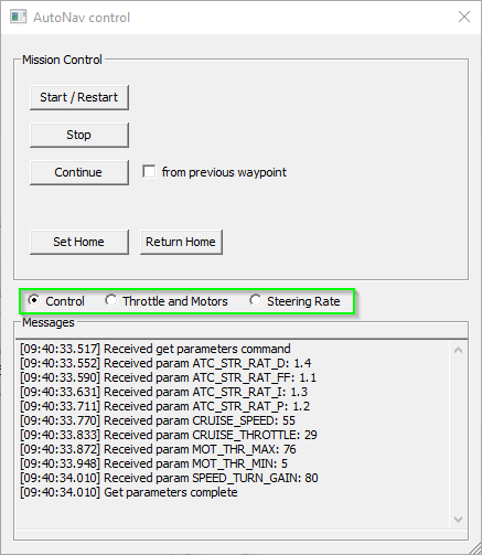
Control view
The Control view allows one to control the mission of the ASV.
-
Start/Restart
Instructs the AutoNav to start its mission in autonomous mode, starting at the first waypoint -
Stop
Puts the AutoNav unit in manual mode. If the unit was in autonomous mode already, this means it will stop its mission. -
Continue
Puts the AutoNav unit in autonomous mode. If the unit has previously been stopped, this will make it continue its mission.
The 'from previous waypoint' checkbox determines how it will continue its route.
If it is not checked, the system will simply continue to the waypoint it was trying to reach when it was stopped.
If the check box is checked, the system will first return to the last visited waypoint and continue its mission from there.
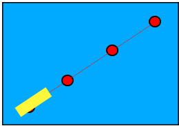
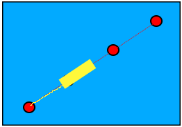
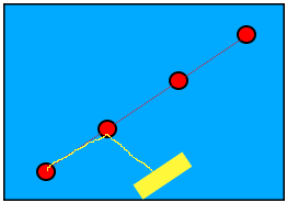
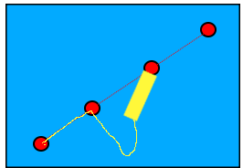
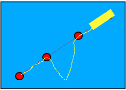
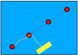
The purpose of this option is to guarantee proper coverage in case the system has drifted while it was stopped:
|
Continue from previous waypoint |
Mission is started |
Mission is stopped |
Vessel drifts |
Mission is continued |
End of mission |
|---|---|---|---|---|---|
|
No |
|
|
|
|
|
|
Yes |
|
|
|
|
|
-
Set Home
Set the system's home location to the current location -
Return Home
Command the system to return to the home location
Note
The Home location is typically set to the location at which the system is armed (unless there is no proper GPS fix at that time).
The Home location can be changed to the current location of the system with the 'Set Home' button.
Throttle and Motors view
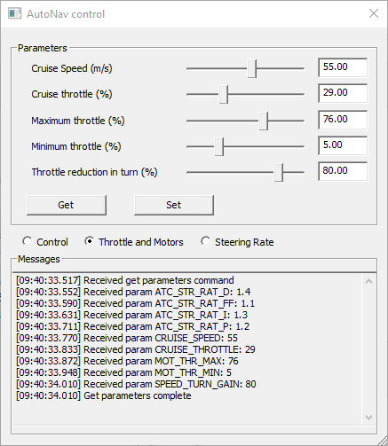
This view allows the user to get and set parameters related to throttle and motor control for the auto pilot:
-
Cruise speed
-
Cruise throttle
-
Maximum throttle
-
Minimum throttle
-
Throttle reduction while making a turn
Steering Rate view
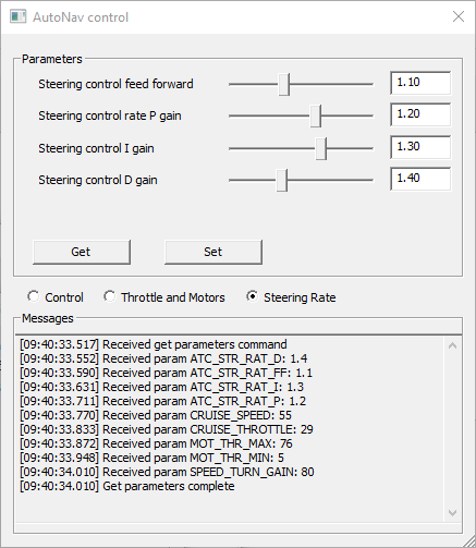
-
Steering control feed forward
-
Steering control rate P gain
"Converts the turn rate error (in radians/sec) to a steering control output (in the range -1 to +1)" -
Steering control I gain
"Corrects long term error between the desired turn rate (in rad/s) and actual" -
Steering control D gain
"Compensates for short-term change in desired turn rate vs actual"
Customization
Warning
Only change the supported parameters if you are familiar with the MavLink protocol.
It is possible to change which parameters can be controlled by the driver. The Qinsy installation contains a file that determines which parameters can be controlled.
This file is located under <Qinsy installation directory>\\Drivers\Settings\MavlinkParam.json.
In order to edit this file, copy it to public documents <public documents>\QPS\Qinsy\Drivers\Settings (public documents is typically located at C:\Users\Public\Document) and open the copied file for editing.
Note
The copied file will take precedence over the file in the installation directory.
Copying the file to the public document folder will make sure that your changes to the file are preserved when a new version of Qinsy is installed.
The original file looks like this:
{
"Throttle and Motors" : [
{
"display_name" : "Cruise Speed (m/s)",
"key" : "CRUISE_SPEED",
"min": 0.0,
"max": 100.0,
"interval": 1.0
},
{
"display_name" : "Cruise throttle (%)",
"key" : "CRUISE_THROTTLE",
"min": 0.0,
"max": 100.0,
"interval": 1.0
},
{
"display_name" : "Maximum throttle (%)",
"key" : "MOT_THR_MAX",
"min": 30.0,
"max": 100.0,
"interval": 1.0
},
{
"display_name" : "Minimum throttle (%)",
"key" : "MOT_THR_MIN",
"min": 0.0,
"max": 20.0,
"interval": 0.5
},
{
"display_name" : "Throttle reduction in turn (%)",
"key" : "SPEED_TURN_GAIN",
"min": 0.0,
"max": 100.0,
"interval": 1.0
}
],
"Steering Rate" : [
{
"display_name" : "Steering control feed forward",
"key" : "ATC_STR_RAT_FF",
"min": 0.0,
"max": 3.0,
"interval": 0.01
},
{
"display_name" : "Steering control rate P gain",
"key" : "ATC_STR_RAT_P",
"min": 0.0,
"max": 2.0,
"interval": 0.01
},
{
"display_name" : "Steering control I gain",
"key" : "ATC_STR_RAT_I",
"min": 0.0,
"max": 2.0,
"interval": 0.01
},
{
"display_name" : "Steering control D gain",
"key" : "ATC_STR_RAT_D",
"min": 0.0,
"max": 4.0,
"interval": 0.01
}
],
"Parameters" :
[
]
}
The file uses the JSON format to describe the properties of a parameter.
A parameter consists of the following properties:
-
display name: This is the name that is shown in the user interface.
-
key: The key of the parameter in the MavLink protocol
-
min: The minimum value for the parameter
-
max: The maximum value for the parameter
-
interval: The increment/decrement to the parameter value when moving the slider in the user interface (typically 1.0)
The parameters are grouped in three collections of parameters:
-
Throttle and Motor
-
Steering Rate
-
Parameters
The first two directly correlate to the two view modes with the same name. Adding, removing or changing parameters in these groups will change the parameters shown in the driver for those groups.
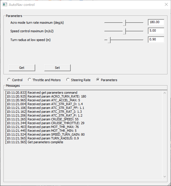
It is also possible to add additional parameters to the 'parameters' collection. This will introduce a new view mode in the driver in which you can control those parameters.
Below is an example of a file in which additional parameters have been added and the corresponding change in the driver's user interface.
{
"Throttle and Motors" : [
{
"display_name" : "Cruise Speed (m/s)",
"key" : "CRUISE_SPEED",
"min": 0.0,
"max": 100.0,
"interval": 1.0
},
{
"display_name" : "Cruise throttle (%)",
"key" : "CRUISE_THROTTLE",
"min": 0.0,
"max": 100.0,
"interval": 1.0
},
{
"display_name" : "Maximum throttle (%)",
"key" : "MOT_THR_MAX",
"min": 30.0,
"max": 100.0,
"interval": 1.0
},
{
"display_name" : "Minimum throttle (%)",
"key" : "MOT_THR_MIN",
"min": 0.0,
"max": 20.0,
"interval": 0.5
}
],
"Steering Rate" : [
{
"display_name" : "Throttle reduction in turn (%)",
"key" : "SPEED_TURN_GAIN",
"min": 0.0,
"max": 100.0,
"interval": 1.0
},
{
"display_name" : "Steering control feed forward",
"key" : "ATC_STR_RAT_FF",
"min": 0.0,
"max": 3.0,
"interval": 0.01
},
{
"display_name" : "Steering control rate P gain",
"key" : "ATC_STR_RAT_P",
"min": 0.0,
"max": 2.0,
"interval": 0.01
},
{
"display_name" : "Steering control I gain",
"key" : "ATC_STR_RAT_I",
"min": 0.0,
"max": 2.0,
"interval": 0.01
},
{
"display_name" : "Steering control D gain",
"key" : "ATC_STR_RAT_D",
"min": 0.0,
"max": 4.0,
"interval": 0.01
}
],
"Parameters" :
[
{
"display_name" : "Acro mode turn rate maximum (deg/s)",
"key" : "ACRO_TURN_RATE",
"min": 0.0,
"max": 360.0,
"interval": 1.0
},
{
"display_name" : "Speed control maximum (m/s2)",
"key" : "ATC_ACCEL_MAX",
"min": 0.0,
"max": 10.0,
"interval": 0.1
},
{
"display_name" : "Turn radius at low speed (m)",
"key" : "TURN_RADIUS",
"min": 0.0,
"max": 10.0,
"interval": 0.1
}
]
}
Note
A maximum of 5 parameters per group can be controlled by the driver.
If you configure more parameters, the additional ones will be ignored by the driver.