
Description
Driver to decode pipe tracker or cable tracker data, depth of, ROV altitude (or depth) and Signal Strength data from a TSS 340, 350 or 440 output string.
The driver automatically recognizes the "T", "I" and "S" records.
To compute a cable position, the Qinsy Multibeam support must be enabled.
Driver Information
|
Driver |
TSS 340/440/350 |
Interface Type |
- |
Driver Class Type |
Terminated |
|---|---|---|---|---|---|
|
No |
Input / Output |
Input |
Executable |
DrvTSS350.exe |
|
|
Related Systems |
|
||||
|
Related Pages |
|
||||
Coding Notes
Decoding Notes
The TSS tracker distances are output in either centimeters or millimeters, but these are converted to meters by the TSS driver.
The driver decodes the TSS tracker offsets as (two) multibeam echosounder beams.
-
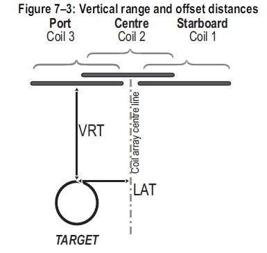
Beam 1 represents the actual pipe target. It contains the vertical distance between the tracker reference point (reference line of the coil array) and the target.
-
Beam 2 represents the seafloor above or below the detected pipe or cable.It contains the vertical distance between the tracker reference point and the sea bottom.
The Z value of beam 2 is obtained by subtracting the Depth of Cover value from the Z value of beam 1 (+ value means buried), The X (across) value is taken from beam 1.
Source: TSS manual
If lateral or vertical offset field(s) contains '???' then the multibeam data will not be decoded if the driver selected is “TSS 340/440/350 Pipe/Cable Tracker”. To decode the multibeam data anyways, please select the “TSS 340/440/350 Pipe/Cable Tracker (Ignore Offset Quality)“ driver instead. In that case, the X and Z value of beam 1 will be set to 0.
If Cover Thickness field contains '???' then the last valid decoded cover thickness is used to calculate the beam to Z value and the Quality indicator of this beam is forced to 99 to indicate it is not valid.
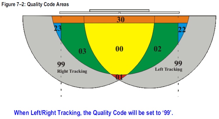
The Quality field 'Q' is ignored, instead the Check code field is used as the beam's quality indicator. A value of 0 is best quality, 99 worst quality.
Source: TSS manual
Qinsy Config
Multibeam Echosounder
Add a Multibeam Echosounder System to your template setup.
The TSS pipe/cable tracker is not a real multibeam data but the horizontal and vertical cable tracker offset can be decoded as beam XZ results and therefore stored as points with absolute co-ordinates in a DTM point processing file (QPD).
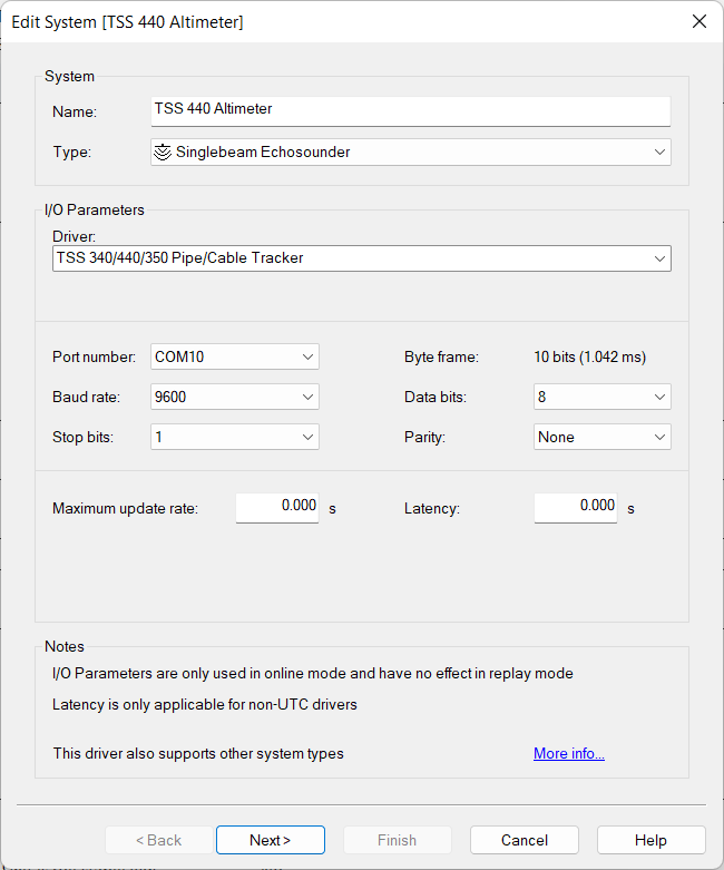
First Wizard page
Selecting the correct driver depends on how you want to use your setup configuration:
-
Normal configuration
When using the “TSS 340/440/350 Pipe/Cable Tracker“ driver and when no valid cable tracking result available no multibeam results will be generated. -
Ignoring quality
When using the “TSS 340/440/350 Pipe/Cable Tracker (Ignore Offset Quality)” driver it will ignore the quality. Therefore when there are no valid cable tracking result are available it keeps generating multibeam results with X and Z offsets of 0. -
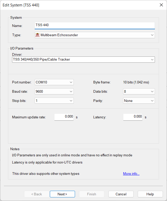
I/O
Configure the corresponding interface parameter, and use the same interface parameters for all other ‘TSS 340/440/350 Pipe/Cable Tracker’ systems in your template setup. -
Maximum update rate
Just leave to 0.000 seconds
Second Wizard Page
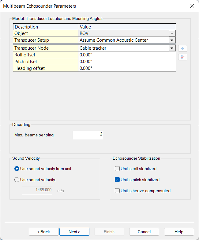
-
Select the correct Transducer Node location.
Normally this will be the middle of the center TSS coil frame mounted on the ROV. -
Set the Max. beams per ping: 2
Beam 1 indicates 'top of utility (cable/pipe)'.
Beam 2 indicates 'top of seabed'. -
Stabilization
It is strongly recommended to correct the TSS data (lateral and vertical offset) by the roll angle. Otherwise, the pipe or cable will be in an absolutely wrong position in a roll affected behaviour.A pitch correction is not necessary as long as the TSS system is always measuring the shortest distance between the coil center and the target. Therefore you need to set 'Unit is pitch stabilized'
Third Wizard Page
Just leave all values on this page at their defaults.
Fourth Wizard Page
Just leave all values on this last page at their defaults.
Singlebeam Echosounder
Add an Singlebeam Echosounder system to your template setup.
This will decode the Altimeter value and allows that the measurement can be positioned on it’s own location to compute the seafloor height.
First Wizard page
Selecting the correct driver depends on how you want to use your setup configuration:
-
Normal configuration
When using the “TSS 340/440/350 Pipe/Cable Tracker“ driver and when no valid altitude result are available no single beam results will be generated. -
Ignoring quality
When using the “TSS 340/440/350 Pipe/Cable Tracker (Ignore Offset Quality)” driver it will ignore the quality. Therefore when there are no valid altitude result available it keeps generating soundings with a value of 0. -
I/O
Use the same interface parameters for all other ‘TSS 340/440/350 Pipe/Cable Tracker’ systems in your template setup. -
Maximum update rate
Just leave to 0.000 seconds
Second Wizard Page
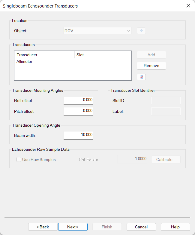
Add the transducer located no Slot ID required driver only contains a single result.
Third Wizard Page
Just leave all values on this page at their defaults.
Underwater sensor
Add an underwater sensor system to your template setup.
This will decode either the ROV attitude (or depth) from the same input string.
First Wizard page
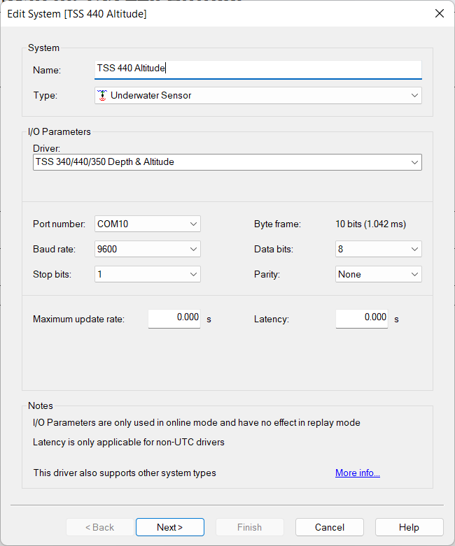
Select driver: “TSS 340/440/350 Depth & Altitude” optionally with (Ignore Quality) option
-
I/O
Use the same interface parameters for all other ‘TSS 340/440/350 Pipe/Cable Tracker’ systems in your template setup. -
Maximum update rate
Just leave to 0.000 seconds
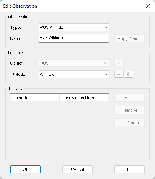
Second Wizard Page
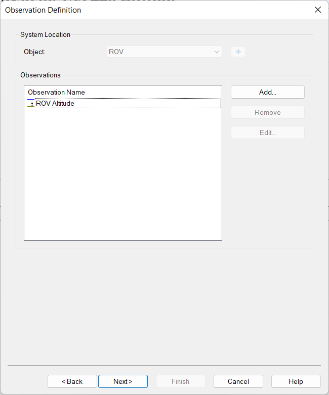
Add your Observations could be either ROV Altitude or ROV Depth
Third Wizard Page
You may check that the unit is set to meters all other values can be on this page can be left at their defaults.
Miscellaneous System
The "Depth of Cover" and "Signal Strength" fields can be decoded (and displayed) as a "generic observation". Add an auxiliary system of type "Miscellaneous system" to the database, select the "TSS 340/350 Depth of Cover / Signal Strength" driver; use the same I/O parameters as with the MBE driver (if it was defined).
First Wizard page
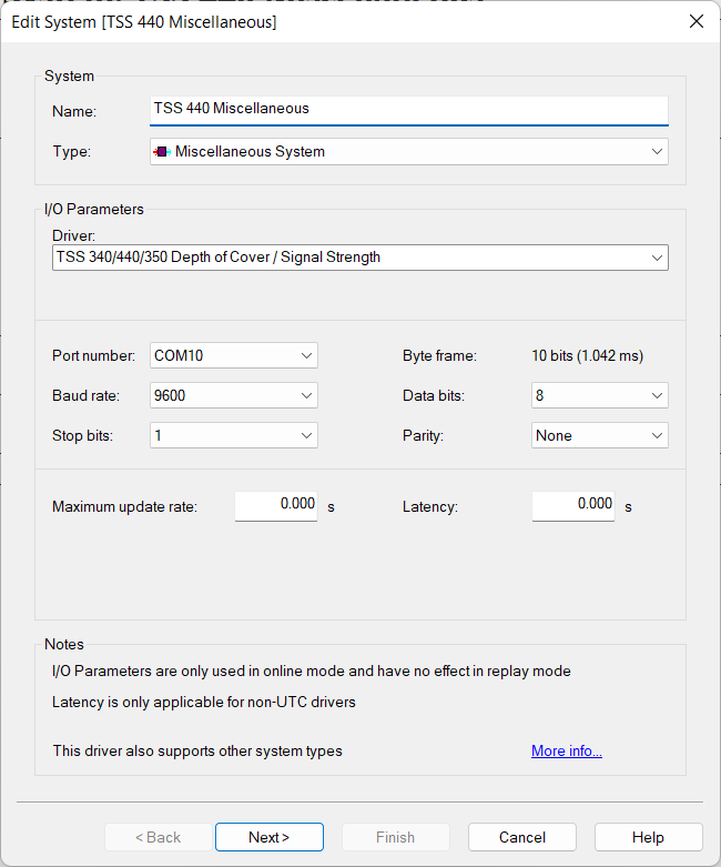
Select driver: “TSS 340/440/350 Depth of Cover / Signal Strength” optionally with (Ignore Quality) option
-
I/O
Use the same interface parameters for all other ‘TSS 340/440/350 Pipe/Cable Tracker’ systems in your template setup. -
Maximum update rate
Just leave to 0.000 seconds
Second Wizard Page
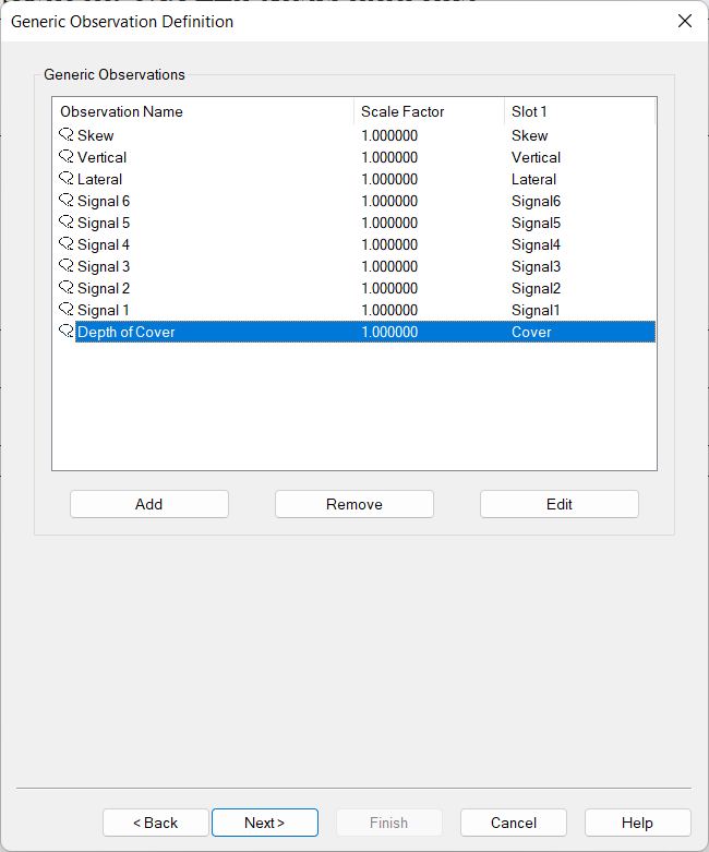
Here you can add up to ten unique generic observations that you may want to monitor.
Each generic observation needs a unique Slot Id so the driver knows which field to decode.
It is highly recommended to use the drop-down selection for the correct Slot Id:
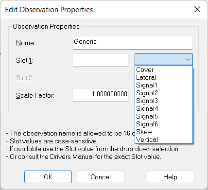
Of course you can change the default name for each observation as long as it doesn't exceed 16 characters.
Third Wizard Page
You may leave all values on this page at their defaults.
Table Overview Slot Id
Note that the driver is backwards compatible with the original slot Id’s that where originally from 0 till 6.
|
Slot Id *) |
Generic Observation |
Unit **) |
Supported record format |
|---|---|---|---|
|
Lateral |
Lateral Offset |
Meters |
All |
|
Vertical |
Vertical offset |
Meters |
All |
|
Cover |
Depth of Cover |
Meters |
All |
|
Skew |
Skew Angle |
Degrees |
'S' record only |
|
Signal1 |
Signal Strength 1 |
µV |
'S' and 'T' record |
|
Signal2 |
Signal Strength 2 |
µV |
'S' and 'T' record |
|
Signal3 |
Signal Strength 3 |
µV |
'S' and 'T' record |
|
Signal4 |
Signal Strength 4 |
µV |
'S' and 'T' record |
|
Signal5 |
Signal Strength 5 |
µV |
'S' record only |
|
Signal6 |
Signal Strength 6 |
µV |
'S' record only |
*) Note that the Slot Id is case-sensitive.
**) The original unit from the field value is automatically converted to the unit as mentioned in the table.
Qinsy Online
Online
Controller setup
To exclude invalid beam data from the result dtm's you can flag the data based on the beam quality indicator value. Note that for beam 2 the Quality indicator is set to 99 if the decoded "Depth of Cover" is invalid.
Displays
It is possible to set an alert on the check code (quality figure) in the Alert Display. To do so select a Raw data alert of the type "Quality indicator outside limit".