
Description
This driver can be used to interface to StarFish sidescan sonar family.
As it is a USB based device, make sure to install the proper firmware from the manufacturer before using the device in Qinsy.
Time of arrival and USB
Please note that the sidescan data from the unit is not time synchronized. This means that Qinsy will use the 'time of arrival' to match the sidescan data with other data (e.g. position, motion etc). Due to the technology of USB there is a delay between data arriving at the USB port and the time that the data is available for the OS (and thus, for Qinsy). The exact value of this delay is unpredictable. To keep this delay as short as possible, make sure to connect as few devices as possible to the USB controller the device is connected to.
Driver Information
|
Driver |
StarFish 450/452/990 |
Interface Type |
- |
Driver Class Type |
USB / with U/I |
|---|---|---|---|---|---|
|
- |
Input / Output |
Input |
Executable |
DrvL3Kleinsocket.exe |
|
|
Related Systems |
|
||||
|
Related Pages |
|
||||
Database Setup
Driver
Make sure to choose the correct driver for your device: "StarFish 450/452" for the 450F, 450H and 452F, or "StarFish 990" for the 990F.
Sound velocity
Choose 'Use sound velocity from unit'.
Channels
The C-Max fish supports only two channels at the same time. Make sure to define two channels: one with orientation port and one channel with orientation starboard. The driver will assign the data based on the orientation.
Online
When online, the sidescan can be controlled through the driver user interface:
Status
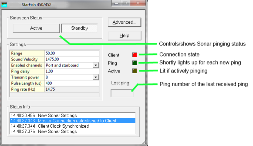
Settings
|
Setting |
Meaning |
|---|---|
|
Range |
Set the operating range. Ranges from 1.0 to 200.0 meters can be set.
|
|
Sound velocity |
The sound velocity used by the unit to calculate range from travel time. |
|
Enabled channels |
Enable or disable port or starboard receivers. |
|
Ping delay |
Normally, the unit will ping as fast as possible. By increasing the ping delay factor beyond 1, the ping rate will be lowered. |
|
Transmit power |
The power used by the transmitter to send out the pulse. Normal values lie between 8 and 10. |
|
Pulse length |
Length of the pulse in micro seconds. |
|
Ping rate |
(Read only) The current ping rate. |
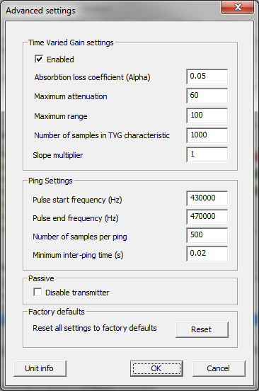
Advanced settings
|
Setting |
Meaning |
|---|---|
|
TVG settings |
|
|
Enable TVG |
Enable or disable the time varied gain algorithm. |
|
Absorption loss coefficient |
The acoustic absorption loss coefficient used by the TVG algorithm in dB/m. |
|
Maximum attenuation |
Maximum attenuation applied to the signal at the start of reception, in Decibels. |
|
Maximum range |
The range at which no attenuation is applied to the received signal, in metres. |
|
Samples |
How many points will be computed in the TVG characteristic. This does not relate to reception samples. |
|
Slope multiplier |
Multiply the slope of the TVG characteristic by this number. |
|
Ping settings |
|
|
Pulse start frequency |
The start frequency of the chirp. |
|
Pulse end frequency |
The end frequency of the chirp. |
|
Number of samples per ping |
The number of samples used to store a complete ping. |
|
Minimum inter-ping time |
Minimum time between two pings.
|
|
|
|
|
Disable transmitter |
Do not send out pulses anymore, only listen. |
|
Reset |
Reset all settings (both advanced and non-advanced) to the factory defaults. |