
Description
Driver for Trimble PPS (Pulse-Per-Second) support. Driver to be used to obtain highly accurate PPS pulse and UTC string from a Trimble GNSS receiver.
The pulse can be used for exact time-tagging.
The PPS pulse is generated as a TTL pulse on a port of the Trimble receiver. At the same time an ASCII output string with the exact UTC time of the pulse is available at one of the I/O ports of the receiver.
Driver Information
|
Driver |
Trimble UTC |
Interface Type |
Serial |
Driver Class Type |
|
|---|---|---|---|---|---|
|
Yes |
Input / Output |
Input |
Executable |
DrvQPSTerminated.exe TIMETAG |
|
|
Related Systems |
|
||||
|
Related Pages |
|
||||
System Configuration
Trimble 4000
To configure a Trimble 4000 receiver for PPS use, press the CONTROL function key on the receiver. Press 'MORE' until '1PPS OUTPUT' is visible in the screen. Select this option by pressing the corresponding button. In the '1PPS OUTPUT' option, 3 parameters can be set: the 1PPS output must be enabled; the slope needs to be positive; the I/O port for the ASCII time string needs to be specified. QPS strongly advises to use I/O port 2 for this purpose, since in most cases I/O port 1 will be in use by the RCI (Remote Control Interface) protocol to collect raw ranges from the receiver. The baud rate for the ASCII time string port must be set in the 'BAUDRATE/FORMAT' option of the CONTROL menu. Qinsy will support baud rates up to 57600 bps, and it is advisable to use a baud rate as high as possible to maximize the throughput speed.
1PPS pulse definition
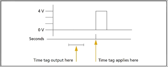
Time tag relation to 1PPS wave form (=Pulse) for Trimble 4000 / R7 / 5700
The pulse is approximately 8 µsec wide, with rise and fall times of about 100 nsec.
Resolution is approximately 40 nsec, but several external factors limit accuracy to approximately 1 µsec:
-
Position errors, especially with user-entered reference. Each meter of error can result in 3 nsec off error in the PPS pulse.
-
Antenna cable length. Each meter of cable adds a delay of about 2 nsec to the satellite signals and a corresponding delay in the 1PPS pulse.
Interfacing Notes
The TTL pulse coming from a Trimble needs to be translated to an RS-232 serial signal before it can be fed into a computer. This is done in the QPS-TTL Trigger Box.
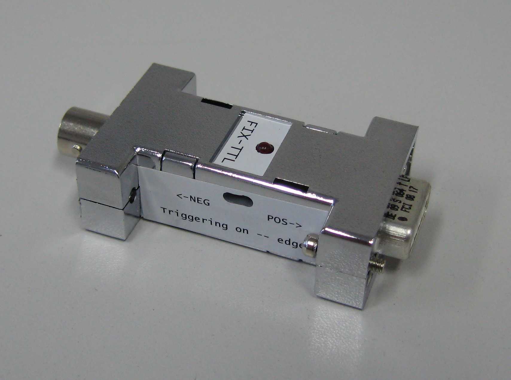
The PPS pulse is fed into the QPS-TTL trigger box and the line out from the trigger box is attached to a computer's serial port. In total the PPS setup will need 2 serial ports: one for the actual pulse, via the QPS-TTL trigger box; the other is needed for the ASCII time string belonging with the pulse.
It is recommended to connect the trigger box to a serial port on the motherboard of the PC. The ASCII string can be connected to any available serial port.
See for information about the QPS-TTL Trigger Box the Trigger Devices section of the Knowledge Base.
The wiring must be as follows:
Trimble 4000
The PPS cable between the Trimble AUX port (LEMO-7) and the trigger box BNC connector (FIX IN):
|
LEMO-7 AUX |
|
BNC QPS |
|---|---|---|
|
Pin 1 |
----- |
Shield |
|
Pin 2 |
----- |
Core |
The trigger cable between the trigger box line out (TO COM) and the computer serial port (on motherboard):
|
DB-9 QPS |
|
DB-9 COM |
DB-25 COM |
|---|---|---|---|
|
Pin 2 |
------- |
Pin 2 |
Pin 3 |
|
Pin 4 |
------ |
Pin 4 |
Pin 20 |
|
Pin 5 |
----- |
Pin 5 |
Pin 7 |
The I/O cable for the serial version of this driver for the ASCII time string and/or RCI between Trimble I/O port and the computer serial port:
|
LEMO-5 I/O |
|
DB-9 COM |
DB-25 COM |
|---|---|---|---|
|
Pin 3 |
-------- |
Pin 3 |
Pin 2 |
|
Pin 4 |
----- |
Pin 5 |
Pin 7 |
|
Pin 5 |
------- |
Pin 2 |
Pin 3 |
|
LEMO-7 I/O |
|
DB-9 COM |
DB-25 COM |
|---|---|---|---|
|
Pin 1 |
------- |
Pin 5 |
Pin 7 |
|
Pin 3 |
------- |
Pin 3 |
Pin 2 |
|
Pin 7 |
------ |
Pin 2 |
Pin 3 |
Online
When the QPS-TTL Triggerbox is connected to Qinsy and the UTC time message is decoded by the driver, the Graphical User Interface (GUI) will show a valid time synchronisation:
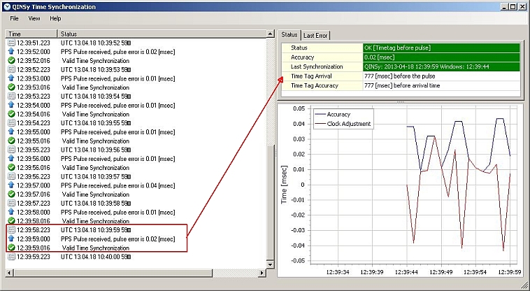
-
The PPS pulse outputted precisely at the whole second
-
The time message contains the time tag of 10:39:59 (UTC) and is detected / has arrived in Qinsy at 12:39:58.223 (hence Local Time = GMT+2, see View Properties).
-
Time Tag Arrival at 10:39:58.223 (UTC) means that the UTC time message has arrived 777 milliseconds BEFORE the pulse it is related to.
-
Time Tag Accuracy is the difference between the the arrival time of the time message and the Time Tag inside the time message. In this case the the Time Tag has arrived 777 milliseconds before the actual time in the message, which means it is applicable 777 milliseconds AFTER the arrival time.
-
Because the UTC time message does not contain decimal second, it will always be equal to the Time Tag Arrival
-
-
-
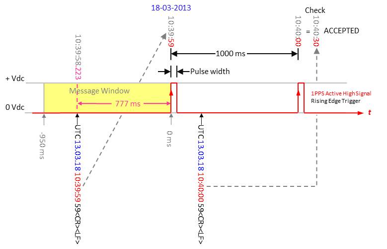
Graphical presentation of the above:
Drivers IO Notes
Since Qinsy CD release 8.10.2012.07.28.1 it is possible to select the Time Tag - Pulse Matching in the Graphical User Interface by means of a drop down list.
The following options are available:
-
Automatic Matching
-
Time tag arrives after the pulse
-
Time tag arrives before the pulse - default
Additional Information
For pin layouts of the Trimble GNSS receivers, please refer to the manuals of your Trimble GNSS receiver
-
Trimble 4000
The following picture shows pin layouts of the connectors and their locations on the rear panel of a Trimble 4000.
Trimble 4000 Receiver - Rear Panel
Trimble 4000 Receiver - Wiring Diagram