Description
Driver with user-interface to decode various items from an RD Instruments (RDI) Acoustic Doppler Current Profiler (ADCP).
The following systems and observations can be created for this driver:
-
Pitch, Roll, Heave Sensor: only pitch and roll are used, heave is not available
-
Gyro Compass
-
Miscellaneous Systems: salinity, pressure, temperature
-
Underwater Sensor: ROV depth, sound velocity
-
Acoustic Doppler Current Profiler
Binary output format PD0 is supported. This driver has user interface to change parameters.
In addition to calculating the average values for speed and direction of the current, the data is also corrected for vessel movement.
Driver Information
|
Driver |
Teledyne RDI WorkHorse ADCP series |
Interface Type |
Serial |
Driver Class Type |
Counted |
|---|---|---|---|---|---|
|
Yes |
Input / Output |
Input and Output |
Executable |
DrvQPSCountedUI.exe |
|
|
Related Systems |
|
||||
|
Related Pages |
|
||||
Coding Notes
Decoding Notes
The RS-232 cable connection must have two-way direction, both receiving (Rx) and transmitting (Tx) data, since this driver will send commands to the unit and will receive data ensembles.
Encoding Notes
Below an overview of some of the commands that can be used to control the ADCP.
How to use these commands: see Active Driver Interface.
Control system commands
|
Command |
Value |
Range |
Unit |
Description |
|---|---|---|---|---|
|
CF |
|
|
|
Flow control |
|
CS |
|
|
|
Start pinging |
Environmental commands
|
Command |
Value |
Range |
Unit |
Description |
|---|---|---|---|---|
|
EX |
01000 |
|
|
Coordinate transformations/corrections |
Timing commands
|
Command |
Value |
Range |
Unit |
Description |
|---|---|---|---|---|
|
TE |
00:00:00.20 |
|
hh:mm:ss.ss |
Time between ensembles (ensemble rate)
|
|
TP |
00:00.00 |
|
mm:ss.ss |
Time between individual pings within ensemble |
Water profile commands
|
Command |
Value |
Range |
Unit |
Description |
|---|---|---|---|---|
|
WP |
30 |
0-16384 |
pings |
No of water profile pings per ensemble
|
|
WS |
500 |
20-800,10-800 or 5-400 |
cm |
Depth Cell size |
|
WN |
30 |
1-128 |
Number of depth cells |
|
Info
For detailed descriptions regarding the commands and an overview of all available commands please refer to the COMMANDS AND OUTPUT DATA FORMAT document by RDI (P/N 957-6156-00) (March 2014)
System Interfacing
No information available.
System Configuration
The system can be configured using the Active Driver Interface or with system specific software, for example WinRiver.
Database Setup
In the Qinsy Database Setup program, the following systems and observations can be created for this driver:
-
Pitch, Roll, Heave Sensor: only pitch and roll are used, heave is not available
-
Gyro Compass
-
Miscellaneous Systems: salinity, pressure, temperature
-
Underwater Sensor: ROV depth, sound velocity
-
Acoustic Doppler Current Profiler
For all drivers the following applies:
-
When using the driver with '(UTC)' in the name, the time as found in the message will be used.
-
If the driver is selected without '(UTC)' in the name the time of arrival in Qinsy will be used.
-
All drivers should use either with or without '(UTC)'. They should not be mixed.
Pitch, Roll, Heave Sensor
The driver is capable of decoding the pitch & roll from the input message
In order to decode the pitch & roll from the input message:
-
Add a Pitch Roll Heave Sensor to your template and select the driver "Teledyne RDI WorkHorse ADCP series (R-P) (UTC)".
-
Select the appropriate serial port.
-
Set the appropriate serial port parameters. Instrument defaults are 9600 baud, 8 data bits, 1 stop bit and no parity.
-
No 'Slot' information is required.
Heading System
The driver is capable of decoding the heading from the input message.
In order to decode the heading from the input message:
-
Add a Gyro Compass system to your template and select the driver "Teledyne RDI WorkHorse ADCP series (UTC)".
-
Select the appropriate serial port.
-
Set the appropriate serial port parameters. Instrument defaults are 9600 baud, 8 data bits, 1 stop bit and no parity.
-
The 'Slot number 1' field on the next page should be set to 'HDG'.
Miscellaneous System
The driver is capable of decoding a number of miscellaneous observations from the input message:
-
Salinity
-
Pressure
-
Temperature
In order to decode any of these miscellaneous observations:
-
Add a Miscellaneous System to your template and select the driver "Teledyne RDI WorkHorse ADCP series (UTC)".
-
Select the appropriate serial port.
-
Set the appropriate serial port parameter. Instrument defaults are 9600 baud, 8 data bits, 1 stop bit and no parity.
-
Select the appropriate value for the 'Slot 1' field.
Available are:
|
Slot 1 |
Observation |
|---|---|
|
SAL |
Salinity |
|
PRS |
Pressure |
|
TMP |
Temperature |
Underwater Sensor
The driver is capable of decoding the transducer depth and sound velocity from the input message.
In order to decode the transducer depth and/or sound velocity from the input message:
-
Add an Underwater Sensor to your template and select the driver "Teledyne RDI WorkHorse ADCP series (UTC)".
-
Select the appropriate serial port.
-
Set the appropriate serial port parameters. Instrument defaults are 9600 baud, 8 data bits, 1 stop bit and no parity.
-
Select the appropriate value for the 'Slot 1' field.
Available are:
|
Slot 1 |
Observation |
|---|---|
|
DPT |
ROV Depth |
|
SND |
Sound Velocity |
Acoustic Doppler Current Profiler
To interface the RD Instruments Acoustic Doppler Current Profiler with Qinsy:
-
Select system type: Acoustic Doppler Current Profiler
-
Driver: "Teledyne RDI WorkHorse ADCP series (UTC)"
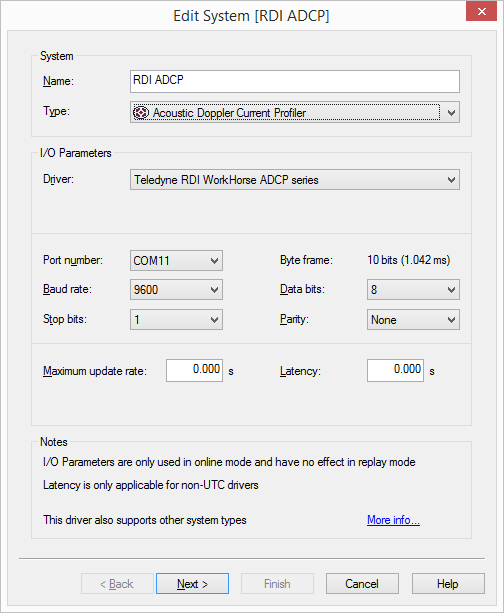
Make sure you set the baud rate as high as possible and that the FIFO buffers of the serial port are disabled (set as low as possible).
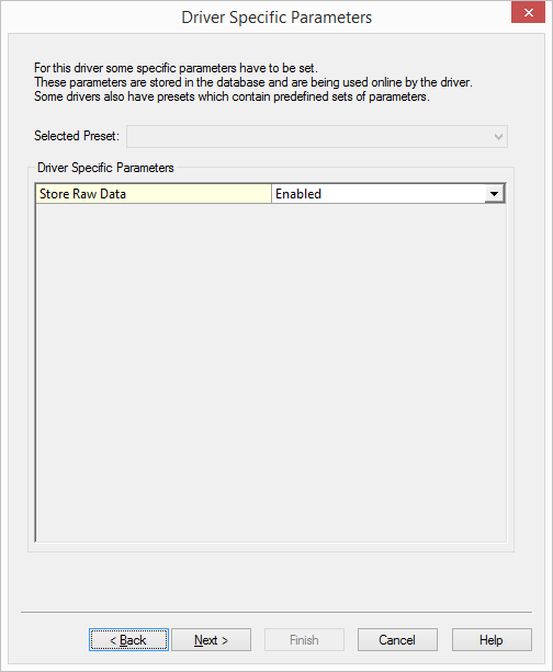
Raw data storage is only needed for problem solving when QPS Support asks for this.
Select the location at which the ADCP is mounted:
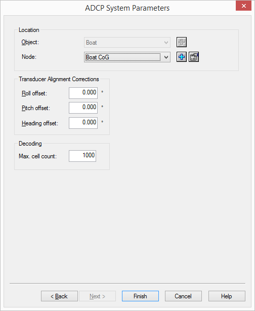
Set the 'Max. cell count' to the maximum number of ADCP depth cells that you expect to receive from the instrument
Warning
There are no procedures to determine the alignment correction in Qinsy. Please refer to the manufacturer procedures to determine the heading offset.
Qinsy Online
Displays
The ADCP data can be shown in a number of displays
-
Navigation Display
-
ADCP Display
-
Observation Physics
-
Generic Display
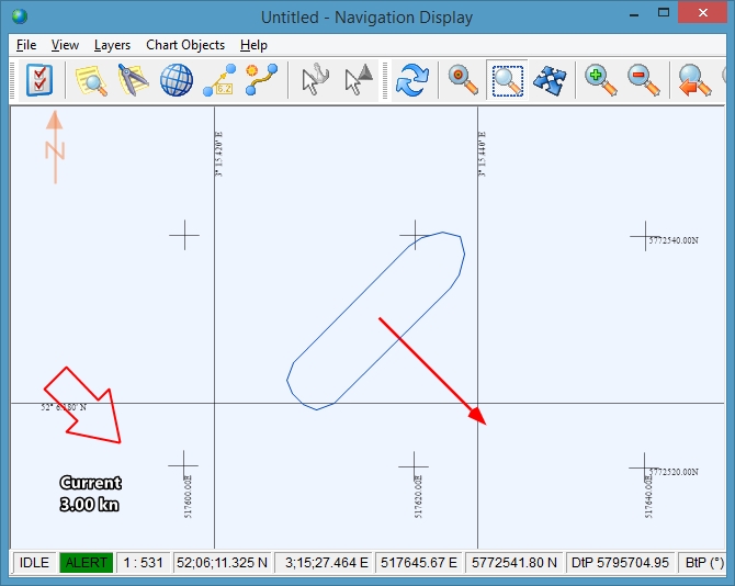
Navigation Display
In the Navigation display the average speed and direction of the current can be visualized, using vectors and a text markup.
The values are corrected for vessel attitude:
-
The arrows show the direction of the current with text markup indicating the speed.
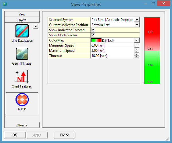
-
These settings are accessible and can be adjusted via the View Properties of the Navigation display.
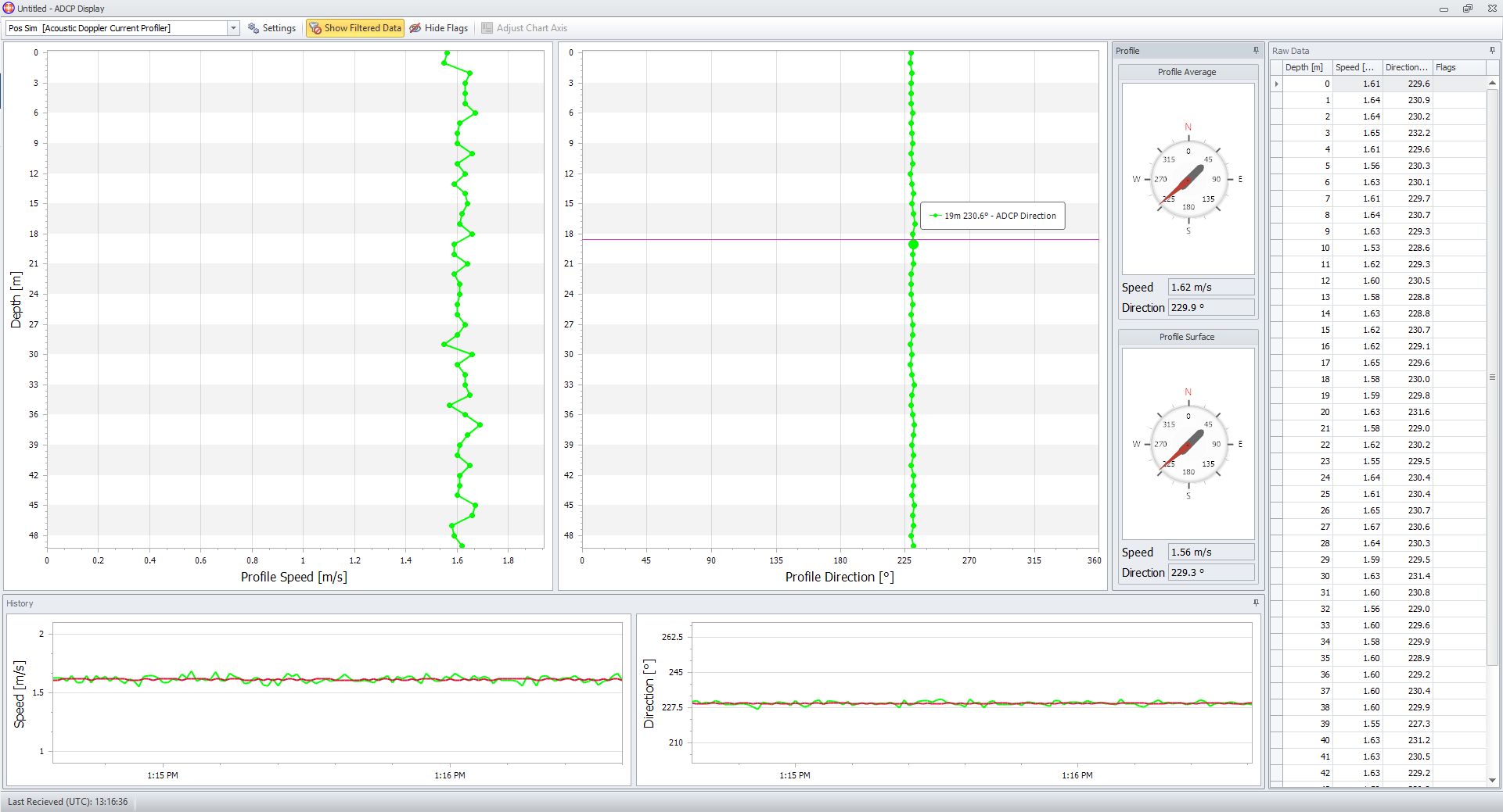
ADCP Display
The ADCP display shows the ADCP current direction and speed data in the following charts:
-
Profile charts through the water column;
-
History charts on average and surface;
-
Compass view on average and surface;
-
Raw data.
Info
The information bar of the display can contain warnings on decoded ADCP data
Generic display
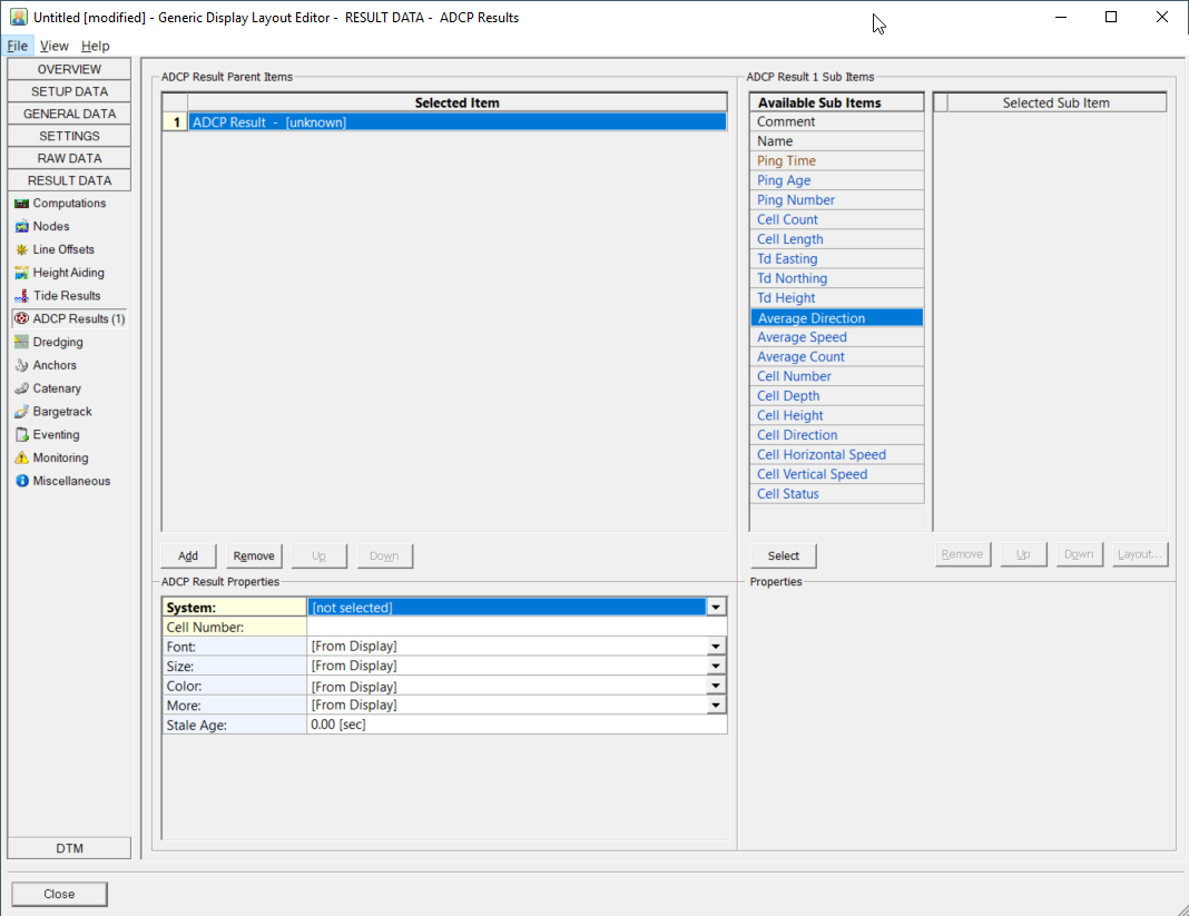
Both Raw and ADCP results data can be shown.
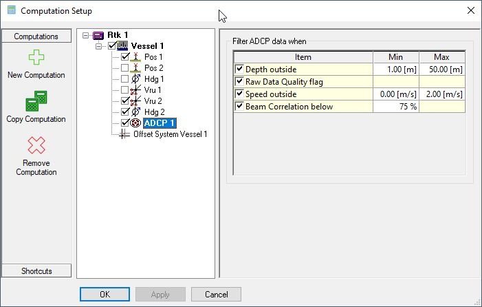
Computation Settings
There are additional controls (filters) in the Computation Setup that can influence how the average is calculated:
-
Depth outside (range)
-
Raw Data Quality flags
-
Speed outside (range)
-
Beam Correlation percentage
Active Driver Interface
The user-interface can be found in the Windows task bar.
The driver is active, meaning commands can be sent directly to the unit by the user.
Use the Load button to browse for a configuration text file containing predefined commands.
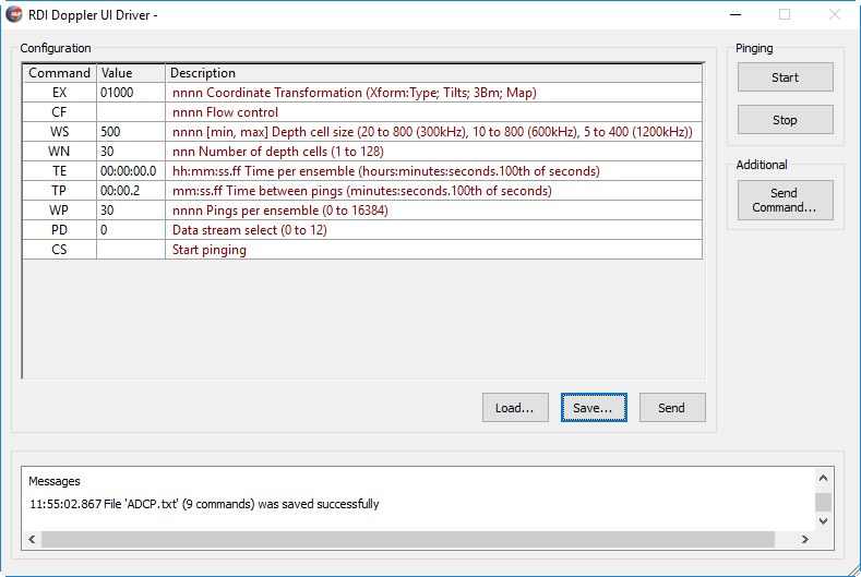
Note that the EX Coordinate transformations/corrections needs to be set to 01000
The text file is a common method and is also used in other software.
Below the suggested minimum commands, for further details about encoding notes see tab Coding Notes:
EX01000 CF WS500 WN30 TE00:00:00.0 TP00:00.2 WP30 PD0 CS
Logging
When recording is enabled, the data is stored in the Qinsy database and can be used for Replay. The ADCP data is also available in the Generic Output.
Additional Information
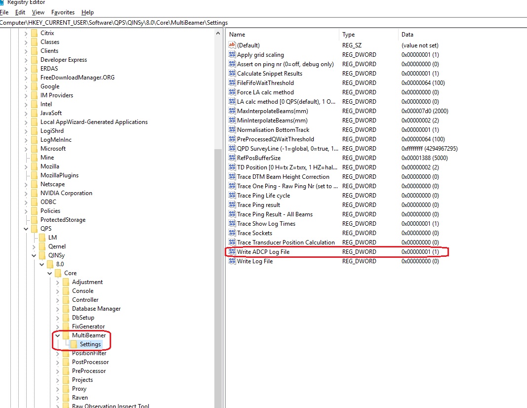
Registry settings
To log data to a text file in the log folder use the following registry key: