
Description
Driver for decoding the data from the Teledyne Odom ECHOTRAC E20 singlebeam echosounder via a network.
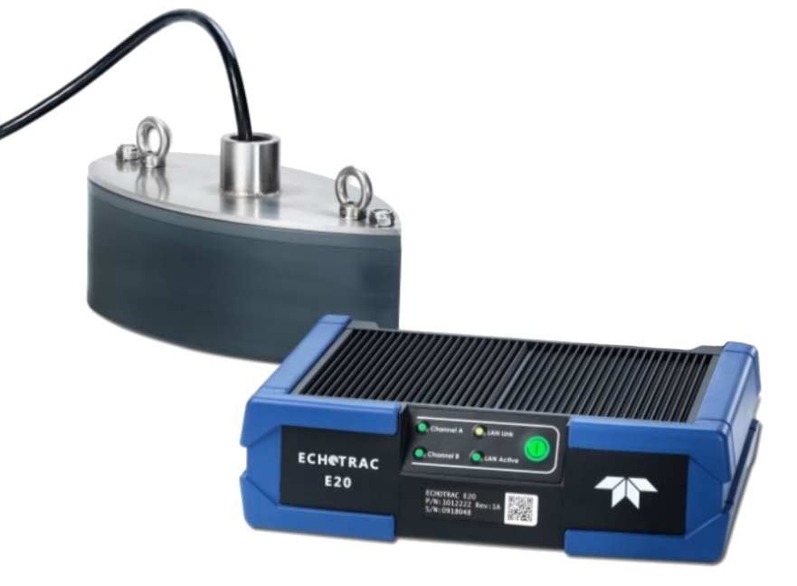
Driver decodes depth underneath the transducer, water column data, draft, sound velocity, heave and other miscellaneous data from the SBES UI.
Driver Information
|
Driver |
Teledyne Odom ECHOTRAC E20 |
Interface Type |
TCP |
Driver Class Type |
Counted |
Created |
|
|---|---|---|---|---|---|---|---|
|
Yes |
Input / Output |
Input |
Executable |
DrvSeabat7K.exe |
Updated |
|
|
|
Related Systems |
|
||||||
|
Related Pages |
|||||||
Coding Notes
Decoding Notes
Communication between the driver and the Singlebeam Echosounder top-side unit goes via a binary data stream, using the Seabat 7K format.
As discussed in the Format tab, this driver primarily uses the 10000, 10004, 10018 and 10027 datagram messages.
For more information about these datagram formats please refer to the Data Format Definition Document - 7K Data Format version 3.14
System Configuration
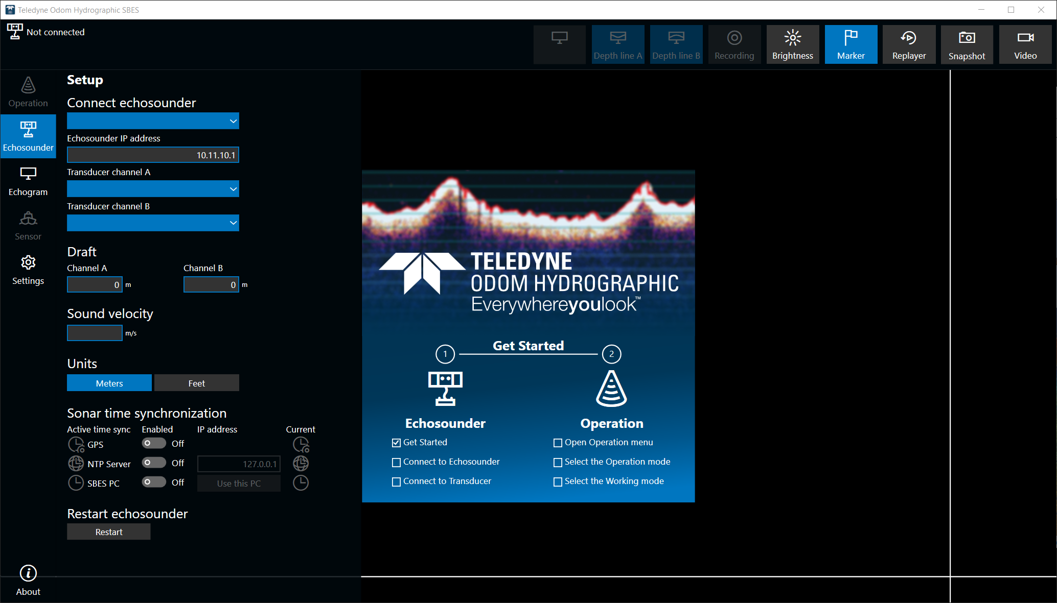
The system will require an initial setup prior to being able to send out data. This will happen in Teledyne Odom Hydrographic SBES UI.
This software will allow the user to adjust the singlebeam echosounder's parameters.
Qinsy Configuration
Database Setup
This chapter describes how this driver is set up in the Database Setup program.
Singlebeam Echosounder
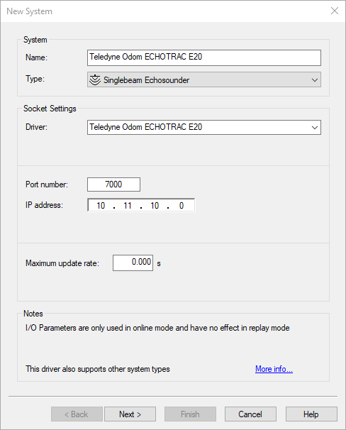
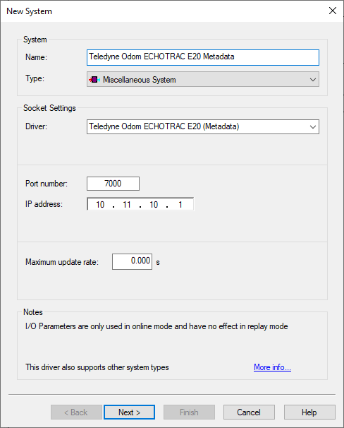
Adding the driver
-
Add a new Singlebeam Echosounder system to the object in your template database.
-
Select driver Teledyne Odom ECHOTRAC E20 .
-
The port number should always be 7000.
-
The IP address should be the IP address of the top-side unit (Not the output IP Address).
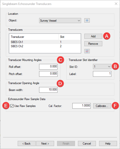
Setting up transducers
-
Select the correct object;
-
Add each transducer separately;
-
Select the node per channel;
-
Set the slot ID per channel;
-
If mounting angles are applicable, enter them here;
-
Change the opening angle if needed;
-
Enable this to decode/store the raw acoustic samples (aka water column data);
-
Only available if TNO add-on is enabled on your license.
-
Singlebeam Echosounder Parameters
Data coming from the singlebeam is always in meters.
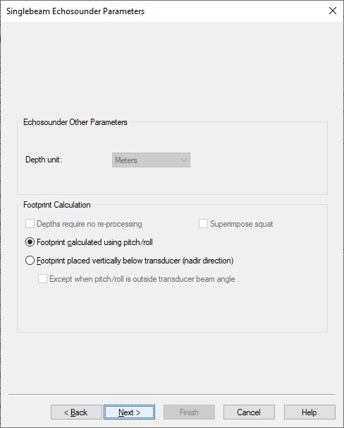
If you need to improve the reported depth with a better sound velocity then this should be changed in the online setup.
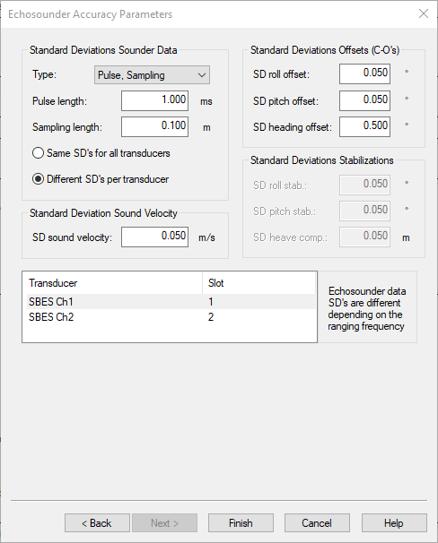
Echosounder Accuracy Parameters
Here the Standard Deviation (SD) data can be entered.
Please be aware that by default this should be set per transducer.
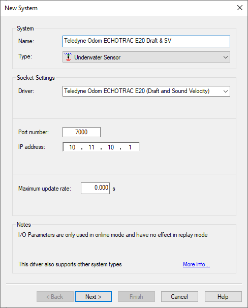
Underwater sensors (Draft and sound velocity)
-
Add a new Underwater Sensor system to your template database.
-
Select driver Teledyne Odom ECHOTRAC E20 (Draft and Sound Velocity).
-
The port number should always be 7000.
-
The IP address should be the IP address of the top-side unit.
-
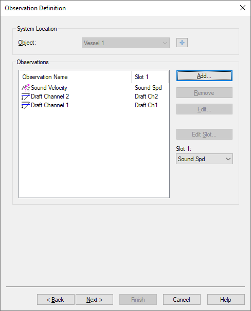
Within this driver a selection of 3 observations can be added:
|
Slot |
Observation |
|---|---|
|
Sound Spd |
Sound Velocity |
|
Draft Ch1 |
Draft Channel 1 |
|
Draft Ch2 |
Draft Channel 2 |
Miscellaneous
-
Add a new Miscellaneous system to your template database.
-
Select driver Teledyne Odom ECHOTRAC E20 (Metadata).
-
The port number should always be 7000.
-
The IP address should be the IP address of the top-side unit.
-
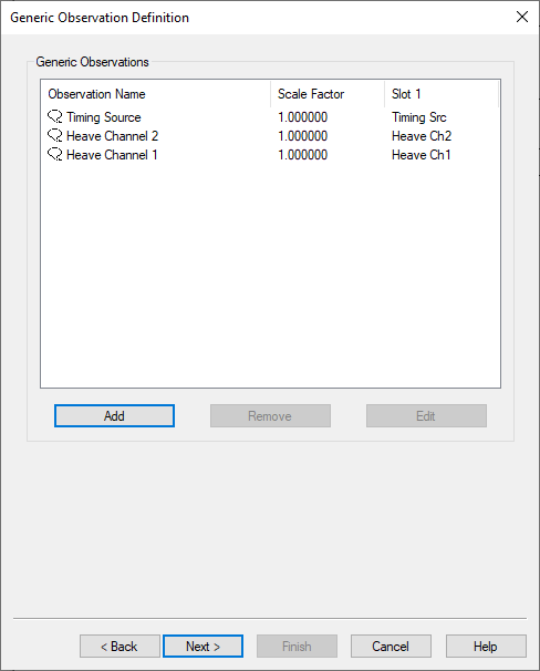
Within this driver a selection of 3 observations can be added:
|
Slot |
Observation |
Comment |
|---|---|---|
|
Timing Scr |
Generic |
Active timing source |
|
Heave Ch1
|
Generic |
Heave Channel 1 & 2 |
|
CTD Ch1
|
Generic |
Corrected Transducer Draft as reported in record 10000.
The sum of the 'Transducer draft' and 'Transducer Index Correction' fields. |
|
Index Ch1
|
Generic |
Transducer index correction |
Qinsy Online
The driver has no user-interface so you should use the various displays to see if data is received and decoded.
Use the Controller's Refraction settings if you wish to improve the reported depth with a better sound velocity.
Controller
The Sound velocity mode can be found in the Controller's Echosounder Settings:
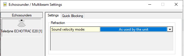
Here you may overrule the default sound velocity as used by the echosounder unit in order to improve the measured depth with a better sound velocity.
-
As used by the unit (default)
Qinsy will use the decoded depth value as reported by the unit.
Use this mode when you're confident that the used sound velocity is accurate enough for your survey specifications. -
From calibrated sound velocity
Use this mode when the echosounder unit is using a default/wrong/out-dated sound velocity and from your own measurement/calibration you have determined a better sound velocity value. -
From velocity profile (recommended)
Use this mode when your setup has an up-to-date sound velocity profile for your survey area.
This mode is recommended because ray-tracing will be used for the entire water-column instead of one fixed sound velocity value. -
From velocity observation
Use this mode when the echosounder unit is using a default/wrong/out-dated sound velocity and you have a sensor defined in your setup that measures in real-time an accurate sound velocity value.
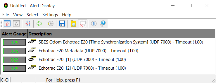
Alert Display
Use an Alert Display to see if data is coming in at the I/O port:
Observation Physics Display
The decoded data can be displayed using an Observation Physics Display:
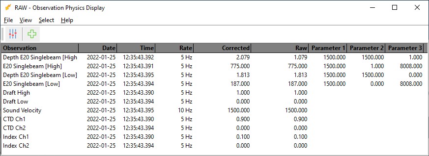
Use View Properties to enable three additional columns to monitor extra information from this system:
-
Extra Column 1 will show you the used sound velocity as reported by the unit and decoded by the driver.
-
Extra Column 2 will either show you the calibrated sound velocity, or the selected velocity observation, or the mean sound velocity from the velocity profile.
So this value depends on the Sound velocity mode as defined in the Controller's Echosounder Settings. -
Extra Column 3 will show the used draft value as reported by the unit.
The difference between the depth value in the Raw and Corrected Column is as follows:
-
Raw Column: the measured depth (i.e. depth below transducer) as reported by the unit. a possible decoded transducer index is taken into account (so this depth is the range between the transducer's lower surface and the seabed)
-
Corrected Column: the reported depth corrected for draft, index and sound velocity, which depends on the Sound velocity mode as defined in the Controller's Echosounder Settings.
Echosounder Display
The decoded depth and raw acoustic samples (a.k.a. water-column) can be visualized using an Echosounder Display:
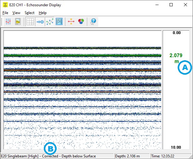
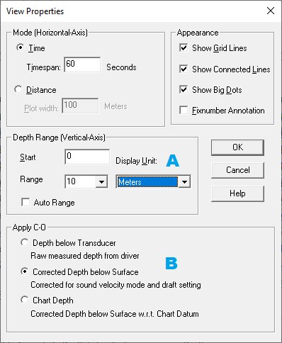
Use the View Properties to change important view settings like A) the unit (meter or feet) or B) the depth value corrected for draft or not.
The displayed depth observation will depend on the refraction settings as defined in the Controller.
B)
Apply C-O
-
Depth below Transducer
The measured depth (i.e. depth below transducer) as reported by the unit and possibly uncorrected for the transducer draft. -
Corrected Depth below Surface
The reported depth corrected for transducer draft and sound velocity as defined in the Controller's Refraction settings. -
Chart Depth
The Corrected Depth below Surface compared to Chart Datum.
C)
Use the System Properties dialog to show the raw sample data.
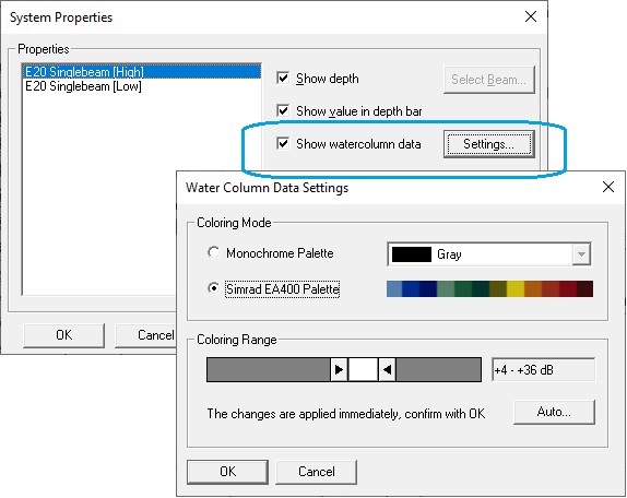
Note that the displayed data in the example screen shot is recorded inside a water tank (hence the non-realistic values).
Additional Information
-
10018 (Echogram Water Column Data) datagram: this format is bound to change, and the change will not be backwards compatible.
-
The driver has been developed with the following software and firmware versions:
Software: Teledyne Odom Hydrographic SBES UI 1.4.2.0;
Firmware: 3.0.535.
7k Data Format version 3.14