
Description
This is a driver with user-interface in order to decode messages from an ROV that Sends LNAV or LNAVUTC.
There are two versions of this driver: a serial one and a network (UDP) one:
-
For the serial driver version, receiving data is done via the same serial COMport
-
For the network driver version, receiving data is done via the same LAN UDP port.
The user-interface for both drivers is exactly the same, only the I/O protocol is different.
Driver Information
|
Driver |
Sonardyne LNAV(UTC) |
Interface Type |
Serial / UDP |
Driver Class Type |
Terminated |
|---|---|---|---|---|---|
|
Yes |
Input / Output |
Input |
Executable |
DrvQPSTerminatedUI.exe
|
|
|
Related Systems |
|
||||
|
Related Pages |
|
||||
Decoding Notes
The following (binary) messages can be received and decoded:
-
Navigation Data Message
This message (normally at 10 Hz input rate) contains the accurate ROV position, depth & altitude, heading, roll & pitch, plus the three axis velocity, acceleration & rotation values. -
Navigation Quality Estimate Message
This message (normally at 1 Hz input rate) contains the standard deviations and quality figures belonging to the values from the Navigation Data Message.
* these message types are combined in the binary package
Interfacing Notes
Format
When data is visible in the I/O Test Utility of Qinsy but it is not decoded online (use the Observation Physics Display) it could be that the string is incomplete.
Changing the output format to Multiplexed in the system will correct for this!
What does it mean?
Multiplexed allows binary and ASCII telegrams to be sent together, it allows for an extra level of wrapping to handle this.
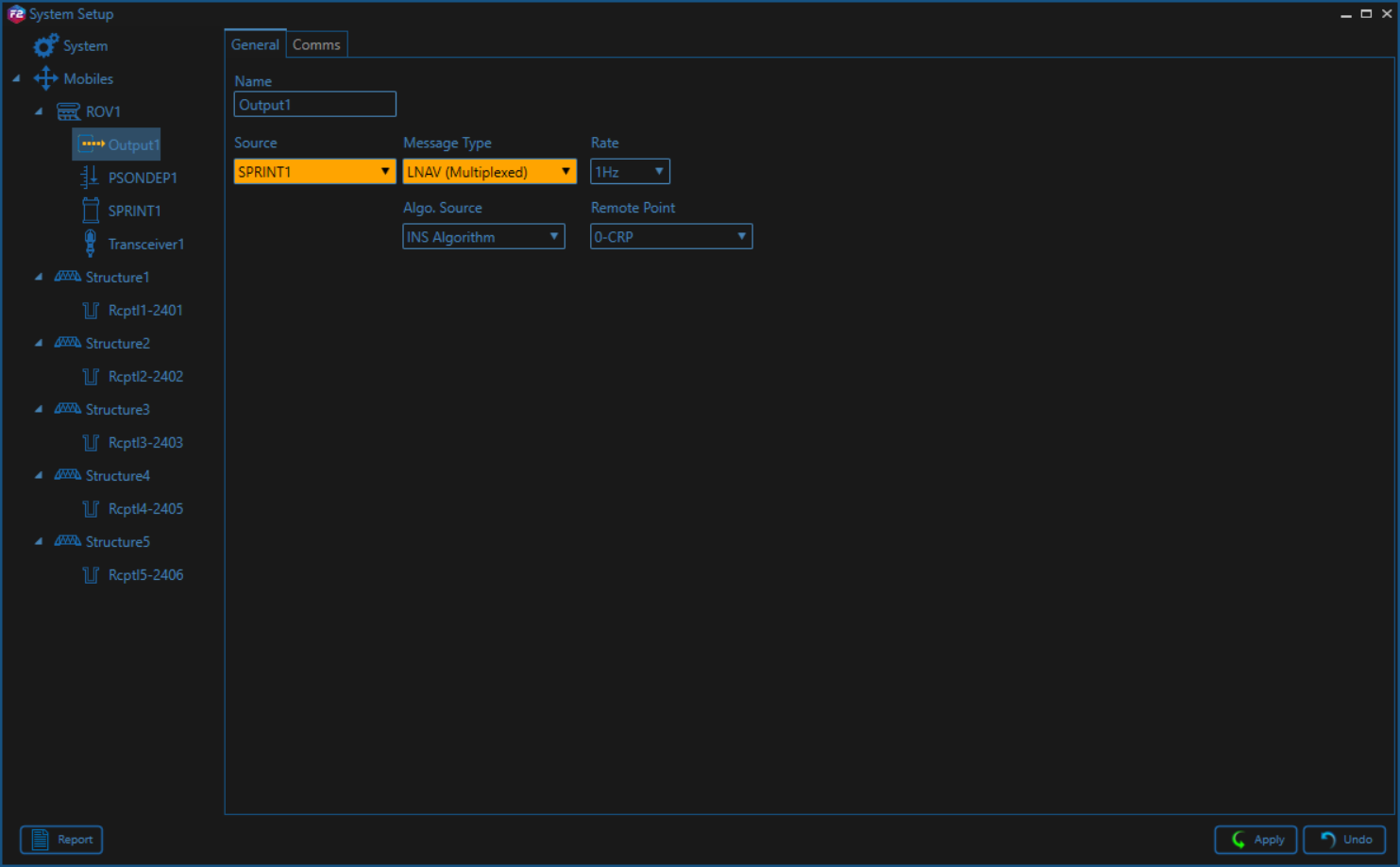
Were can you select this in the Fusion 2 software?
For Fusion 2, click on the setup cogs in the toolbox on the lower left-hand side of the screen.
Right click on the vehicle in the tree and select ‘add output’, set the port and click ok.
Click on ‘edit’ and set the telegram type.
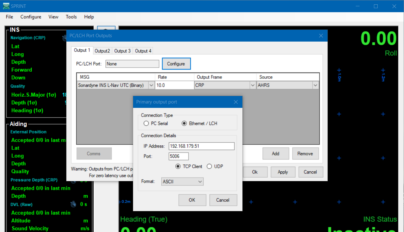
Were can you select this in the Sprint software?
For Sprint, go to Configure>Outputs>PC/LCH ports, select the output to be used.
Click 'configure' (next to port), set the port to be used and change the format from ASCII to multiplexed.
Then add the LNAV (UTC) telegram.
Timing
-
Navigation Data Message (Incoming)
Normally the driver will time stamp the data when it arrives at the COMport (or UDP port), but this may introduce latency due to variable calculations and/or serial/network characteristics.
So, when the unit is interfaced with an external PPS/UTC input, then it is recommended to use the time from the decoded messages in order to time stamp the data.
This can be achieved when the following criteria are met:-
Your template setup has a valid Time Synchronization (PPS) system
-
The so-called 'UTC' driver is selected (See also paragraph DM-0408#cmdline below)
-
The Time System Data Message is received and preferably with an update rate of 1 Hz.
When you are online, check the Messages list (drivers dialog lower pane) to see if it says 'Valid PPS system detected' AND 'Time fields will be used for timestamping'. -
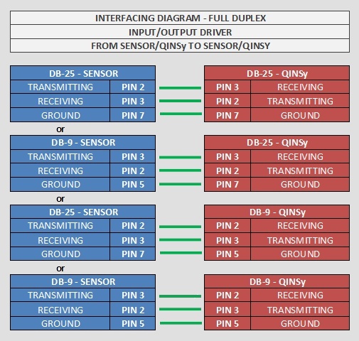
For the serial driver version, output will take place via the same serial COMport as the incoming messages, therefore one should take the following wiring diagram into account when using I/O cables and connectors:
Database Setup
Position
-
In order to decode the position from the Navigation Data message, add a Position Navigation System to the template and select driver "Sonardyne LNAV (Position)".
On the second wizard page, select for Horizontal Datum 'WGS84', but for Vertical Datum select the Mean Sea Level Model (because the height will be derived from the decoded depth, with a negative sign). However, it is highly recommended to set the Height Status to 'Unreliable' in the on-line Computation Setup, in combination with the use of an ROV Depth observation (see below).
Node name as transponder code
When the LNAV driver outputs the $PSIMSSB message ($PSIMSSB,hhmmss,Btp,qqq,errcode,c,o,f,x.xx,y.yy,z.zz,a.aa,i,,*cc) for USBL positioning, the Transponder Code field (Btp) is automatically derived from the object’s node name using the first three characters in Qinsy.
Because the first three characters of the node name are used as the Transponder Code, the node name must start with a valid beacon ID that the receiving INS system will accept.
For example, change the node name as follows:
ROV CoG → M03 CoG
Heading
-
In order to decode the heading from the Navigation Data message, add a Gyro Compass System to the template and select driver "Sonardyne LNAV (Heading)".
Use the same I/O parameters (COMport, baudrate, etc.).
Motion / Attitude
-
In order to decode the pitch and roll (there is no heave) from the Navigation Data message, add a Pitch, Roll and Heave Sensor System to the template and select driver "Sonardyne LNAV (Attitude)". Use the same I/O parameters.
The roll convention must be 'Positive heeling to starboard' and the pitch convention 'Positive bow up'.
Underwater
-
In order to decode a depth observation from the Navigation Data message, add an Underwater Sensor to the template and select driver "Sonardyne LNAV (ROV Depth & Altitude)". Use the same I/O parameters.
On the second wizard page, add an ROV Depth observation. Select for At Node the correct node on the ROV object. The units on the last wizard page must be Meters.
You may also decode the altitude (or height above bottom) which comes directly from a valid Doppler input
Add on the same second page an ROV Altitude observation, and select for the At Node the DVL sensor location on the ROV object. The units on the last wizard page must be Meters.
Notice that this type of observation is not used by the Computation Setup, but it will be decoded, displayed and stored.
Velocities
-
In order to decode the three axes velocity, acceleration and rotation rate observations from the Navigation Data message, add an Acceleration Velocity Sensor system to your database and select the driver "Sonardyne LNAV (Velo, Acc, Rot)". Use the same I/O parameters.
Add the following observations on the second wizard page: Velocity (X, Y and Z), Acceleration (X, Y and Z) and/or Rate-Of-Turn (X, Y and Z).
On the next wizard page, select for the velocity observation unit: Meters / Second, for the acceleration observations: Meters / Second^2, and for the rate-of-turn select Degrees / Second.
Generic Information
-
In order to decode additional information from the Navigation Data and/or Time System Data message, add a Miscellaneous System to the template and select driver "Sonardyne LNAV (Info)". Use the same I/O parameters.
On the second wizard page, add the following five Generic observations:
It is recommended to select the Slot Id from the combo box. The observation name will then be set automatically, but you are free to change this name. -
Observation representing the Navigation Data Mode , with Slot ID 'MODE'.
The value is decoded from the Navigation Data Message. In the Generic Layout Editor you may use the 'MASK' operator on this mode value, in order to extract the individual 'bit' information. Bit 0 means: Data valid, bit 1: Initialised, bit 2: application not enabled, (bit 3-14: reserved) bit 15: System failure
Online
The driver has user-interface, and therefore will always be present in the Windows taskbar.
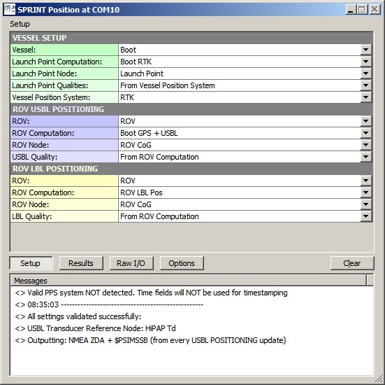
When going on-line for the first time, locate the driver, and change the Setup parameters:
Driver Layout Menu: Setup
|
|
VESSEL SETUP |
|---|---|
|
Vessel: |
Select from the available defined objects the vessel from which the ROV will be launched. |
|
Launch Point Computation: |
Select the computation and node for the launch point of the ROV on the vessel. This node will be formatted and outputted as the NMEA GGA message. |
|
Launch Point Node: |
Select the computation and node for the launch point of the ROV on the vessel. This node will be formatted and outputted as the NMEA GGA message. |
|
Launch Point Qualities: |
Select whether to use the GPS quality flag, Number of satellites and the HDOP value straight from the raw data of the selected Vessel Position System, or enter the values manually.
|
|
Vessel Position System: |
Select the system that is used to position the vessel. This system is used to retrieve the GPS Quality and Number of satellites. |
|
Manual: |
Manual quality values for the output NMEA GGA message. Enter the three values comma-separated ('q, ss, h.h'): GPS Quality, Number of Satellites, HDOP. |
|
|
ROV USBL POSITIONING |
|
ROV: |
Select from the available defined objects the ROV object that is positioned by a USBL system. |
|
ROV Computation: |
Select the USBL computation and node for the ROV. This node will be formatted and outputted as the $PSIMSSB message. Notice that whether this computation is used or the LBL one, depends on the PSIMSSB Position setting in the Options Menu. |
|
ROV Node: |
Select the USBL computation and node for the ROV. This node will be formatted and outputted as the $PSIMSSB message. |
|
USBL Quality: |
Select whether to use positioning error estimates as computed by Qinsy using the selected ROV Computation, or enter the value manually.
|
|
Manual: |
Manual positioning error estimates entry for the output $PSIMSSB message. Enter '±ccc.cc': USBL Quality (or Expected accuracy of the positioning) [m]. |
|
|
ROV LBL POSITIONING |
|
ROV: |
Select from the available defined objects the ROV object that is positioned by an LBL system. |
|
ROV Computation: |
Select the LBL computation and node for the ROV. This node will be formatted and outputted as the $PSIMSSB message. Notice that whether this computation is used or the USBL one, depends on the PSIMSSB Position setting in the Options Menu. |
|
ROV Node: |
Select the LBL computation and node for the ROV. This node will be formatted and outputted as the $PSIMSSB message. |
|
LBL Quality: |
Select whether to use positioning error estimates as computed by Qinsy using the selected ROV Computation, or enter the value manually.
|
|
Manual: |
Manual positioning error estimates entry for the output $PSIMSSB message.
|
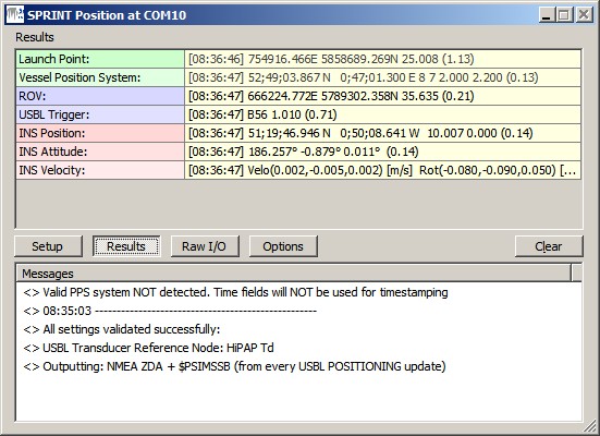
Driver Layout Menu: Results
|
Launch Point: |
The last encoded position for the selected Launch Point Node which will be outputted as NMEA GGA. Displayed are the [Update Time], Easting and Northing, the Height and the age of the data (between brackets) in seconds. If this age exceeds 5 seconds, then the last encoded values are displayed in the color red. |
|
Vessel Positioning System: |
The last decoded statistics from the selected Vessel Position System. Displayed will be the [Update Time], Latitude and Longitude, GPS Quality Indicator, Number of Satellites, HDOP, Age of Differential Corrections and the age of the data (between brackets) in seconds. If this age exceeds 5 seconds, then the last decoded values are displayed in red color. It is this GPS Quality Indicator, Number of satellites and HDOP that will be used to format the output NMEA GGA message, if not overruled by the manually entered values. |
|
ROV: |
The last encoded position for the selected ROV which will be outputted as $PSIMSSB. Displayed are the [Update Time], the Easting and Northing, the Height and the age of the data (between brackets) in seconds. If this age exceeds 5 seconds, then the last encoded values are displayed in the color red. |
|
USBL Trigger: |
Information about the last updated USBL Transponder. This row is only visible when the $PSIMSSB message is outputted on USBL Trigger (see Options Menu). Displayed are the [Update Time], the Transponder Slot, the Seconds between the last two updates and the age of data (between brackets). If this age exceeds 5 seconds, then the last encoded values are displayed in red. |
|
INS Position: |
The last decoded position data from the Navigation Data message. Displayed are the [Update Time], the Latitude and Longitude, Depth, Altitude and the age of the data (between brackets) in seconds. If this age exceeds 5 seconds, then the last decoded values are displayed in red |
|
INS Attitude: |
The last decoded attitude data from the Navigation Data message. Displayed are the [Update Time], the Heading, Pitch, Roll and the age of the data (between brackets) in seconds. If this age exceeds 5 seconds, then the last decoded values are displayed in red. |
|
INS Velocity: |
The last decoded three axis velocity data from the Navigation Data message. Displayed are the [Update Time], Velocity X, Y, Z, Rotation X, Y, Z, Acceleration X, Y, Z and the age of the data (between brackets) in seconds. If this age exceeds 5 seconds, then the last decoded values are displayed in red. |
|
INS Time: |
The last decoded time information from the Time System Data message. Displayed are the [UTC Time], the Source of the UTC time, the expected standard deviation of the UTC time, the time since the last accepted UTC update and the age of the data (between brackets) in seconds. If this age exceeds 5 seconds, then the last decoded values are displayed in red. |
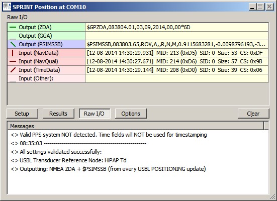
Driver Layout Menu: Raw Data
|
Output (ZDA) |
Last outputted NMEA ZDA message to the serial COM or network UDP port. The indicator cycles when a complete message has been sent. If the last output took place more than 5 seconds ago, it will be displayed in gray. |
|
Output (GGA) |
Last outputted NMEA GGA message to the serial COM or network UDP port. The indicator cycles when a complete message has been sent. If the last output took place more than 5 seconds ago, it will be displayed in gray. |
|
Output (PSIMSSB) |
Last outputted $PSIMSSB message to the serial COM or network UDP port. The indicator cycles when a complete message has been sent. If the last output took place more than 5 seconds ago, it will be displayed in gray. |
|
Input (NavData) |
Last received Navigation Data message at the serial COM or network UDP port. The indicator cycles when a complete message is received. If no valid Navigation Data message is received for more than 5 seconds, then the last received data is displayed in the color gray.
|
|
Input (NavQual) |
Last received Navigation Quality Estimate message at the serial COM or network UDP port. The indicator cycles when a complete message is received. If no valid Navigation Quality Estimate message is received for more than 5 seconds, then the last received data is displayed in the color gray.
|
|
Input (TimeData) |
Last received Time System Data message at the serial COM or network UDP port. The indicator cycles when a complete message is received. If no valid Time System Data message is received for more than 5 seconds, then the last received data is displayed in the color gray.
|
|
Input (Other) |
Last received unknown message at the serial COM or network UDP port. The indicator cycles when a complete message is received. If no other message is received for more than 5 seconds, then the last received data is displayed in the color gray.
|
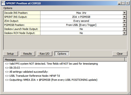
Driver Layout Menu: Options
|
Lock Settings: |
Enable to lock the user-interface settings of the Setup and Options menu, in order to prevent making changes by mistake.
|
|
Show Tooltips: |
When hovering the mouse over the left column rows, you will get some more information. Disable if this becomes annoying...
|
|
Decode INS Position: |
Reduce the number of decoded INS positions from the Navigation Data Message.
Notice that this setting does not affect the decoding of the other observations (Heading, Motion, Velocities, etc), only the positions.
|
|
SPRINT INS Output: |
|
|
ZDA Output: |
Select the desired output update rate for the NMEA ZDA message. Output of this message can only be triggered on time. Every second is recommended. |
|
GGA Output: |
Select the desired output update rate for the NMEA GGA message. Output of this message can only be triggered on time.
|
|
PSIMSSB Position: |
Select the source and the desired output update rate for the $PSIMSSB message
|
|
Deskew Launch Node Output: |
Select Yes in order to skew the time and position of the launch point node to the time of output (NMEA GGA message), using the current SOG and COG. Notice that the SOG and COG depend on the Controller's Computation Setup, Object COG/SOG - Prediction Parameters Settings. The height value is not deskewed. |
|
Deskew ROV Node Output: |
Select Yes in order to skew the time and position of the ROV node to the time of output ($PSIMSSB message), using the current SOG and COG. Notice that the SOG and COG depend on the Controller's Computation Setup, Object COG/SOG - Prediction Parameters Settings. The height value is not deskewed. |
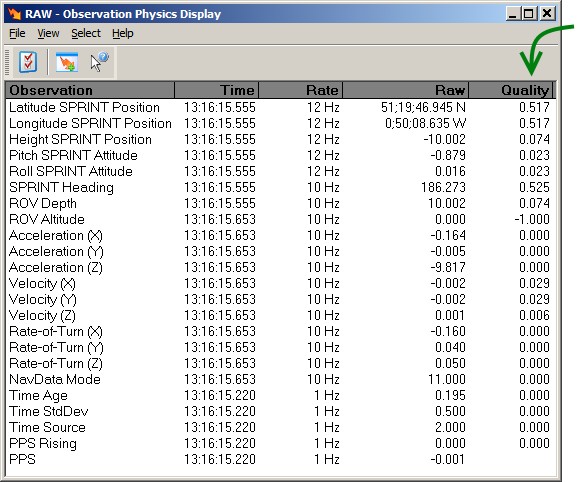
Observation Quality Indicators
All observation values are decoded from the Navigation Data Message, but the accompanying qualities (Standard Deviation, Estimates, Error ellipses) are decoded from the Navigation Quality Estimate message.
The following observations will have a decoded quality indicator:
|
Observation |
Decode Field from Message |
Quality Indicator |
Comment |
|---|---|---|---|
|
Latitude / Longitude |
posMajor / posMinor |
SQRT(posMajor^2 + posMinor^2) |
Horizontal 1 DRMS |
|
Height / Depth |
stdDepth |
|
1 Sigma |
|
Altitude |
n/a |
-1 when Altitude value = 0
|
-1: Invalid
|
|
Heading |
stdHeading |
|
1 Sigma |
|
Pitch / Roll |
stdLevN / stdLevlE |
MAX(stdLevN, stdLevlE) |
1 Sigma |
|
Velocity X / Y |
velMajor / velMinor |
SQRT(velMajor^2 + velMinor^2) |
Velocity RMS |
|
Velocity Z |
velDown |
|
1 Sigma |
|
Acceleration X / Y / Z |
n/a |
always 0 |
|
|
Rotation X / Y / Z |
n/a |
always 0 |
|
|
All Generics |
n/a |
always 0 |
|
Additional Information
Drivers IO Notes
'PPS'
When this command line parameter is used, then the driver will time stamp the decoded observations using the (UTC) timetag, part of the Navigation Data and Time System Data message. But only when your setup has a valid Time Synchronization (PPS) system. When this command line parameter is omitted, then the driver will time stamp the data when it arrives at the COMport (or UDP port), so this may introduce latency.
Notice that this command line parameter is always enabled.
Registry Options
-
As explained above, information in the Results menu will be displayed in red color when the age of the data exceeds five seconds.
This age limit (default 5 seconds) may be changed by modifying the registry key:
'HKEY_CURRENT_USER\Software\QPS\Qinsy\8.0\Drivers\DrvQPSTerminatedUI\<YourDriverName>\Settings\ MaxAgeRawInput'.
(Changing this age value is purely for display purposes. It has nothing to do with the actual decoding of the data) -
Information in the Raw menu will be displayed in gray color when the age of the data exceeds five seconds.
This age limit (default 5 seconds) may be changed by modifying the registry key:
'HKEY_CURRENT_USER\Software\QPS\Qinsy\8.0\Drivers\DrvQPSTerminatedUI\<YourDriverName>\Settings\ MaxAgeRawOutput'.
(Changing this age value is purely for display purposes. It has nothing to do with the actual output of the data) -
Change the following registry key (from '00' (default) to '01') if you also want to show the 'Lock Settings' and 'Show Tooltips' option in the Options menu:
'HKEY_CURRENT_USER\Software\QPS\Qinsy\8.0\Drivers\DrvQPSTerminatedUI\<YourDriverName>\Settings\ ShowAllOptions' -
Change the following registry key (from '01' (default) to '00') if you want to hide the four dark gray separator lines in the Setup menu:
'HKEY_CURRENT_USER\Software\QPS\Qinsy\8.0\Drivers\DrvQPSTerminatedUI\<YourDriverName>\Settings\ ShowSetupHeaders'