
Description
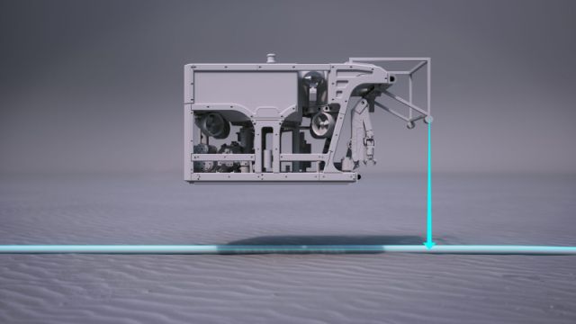
Driver to decode data from the Artemis Cable Tracker, manufactured by SMD, capable of detecting and locating buried power cables and pipelines under the seafloor.
The system is capable of outputting data using several message formats. Note that this driver will only decode data from the Solution message; an NMEA look-a-like ASCII string, starting with $IISOL.
The message contains the estimated position of the cable or pipeline as well as other relevant data.
Typically, one solution message is generated for each measurement interval, but two messages may be generated for some system configurations.
In that case the two (Aft and Forward solution) are distinguished by the first field of the message: the solution identifier.
Driver Information
Click to expand...
|
Interface type |
Serial / UDP / TCP |
|---|---|
|
Yes |
|
|
Input / output |
Input |
|
Related Systems |
|
|
Related Pages |
|
Decoding Notes
System Setup
Click to expand...
The Artemis system comes with the manufactures own software: Artemis Survey.
Use its GUI (Graphical User Interface) to setup the system and make sure to enable the required output message (Solution Message $IISOL) with the correct baudrate and other I/O parameters.
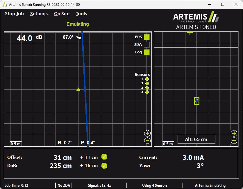
This document doesn’t describe how to use the Artemis Survey software, for more information and details please refer to its own documentation.
Qinsy Database Setup
Click to expand...
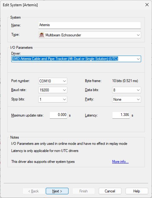
First of all it is important to use the same interfacing settings for all ‘SMD Artemis Cable and Pipe Tracker’ systems in your template setup. These interface settings are defined on every first wizard page.
Because the ARTEMIS has a fixed delay between the actual observations and the time at which the message is output to Qinsy, a fixed latency should be entered for each system that uses the driver.
The latency that should be used is 1.386 seconds and must be entered for all driver variants (Serial / Network / UTC / Non-UTC) on every first wizard page.
Multibeam Echosounder
Add a Multibeam Echosounder System to your template setup.
Of course ARTEMIS data is not real multibeam data but the in real-time detected cable or pipe can be decoded as beam XYZ results and therefore stored as points with absolute co-ordinates in a DTM point processing file (QPD)
First Wizard Page
Selecting the correct driver depends on your ARTEMIS setup configuration:
-
Single System Configuration
Select driver "SMD Artemis Cable and Pipe Tracker (Aft Dual or Single Solution) (UTC)" in case your ARTEMIS setup is configured to work with a single solution.
This driver will only decode data from $IISOL messages with the Solution Identifier field set to 1. -
Dual System Configuration
In case your setup is configured to work in dual solution mode (one solution for the aft frame and one solution for the forward frame) you may add another multibeam echosounder system to your template setup and select driver “SMD Artemis Cable and Pipe Tracker (Forward Dual Solution) (UTC)“.
This driver will only decode data from $IISOL messages with the Solution Identifier field set to 2.
-
I/O
Like said above, use the same interface parameters for all other ‘SMD Artemis Cable and Pipe Tracker’ systems in your template setup.
-
Maximum update rate
Just leave to 0.000 seconds
-
Latency
It is important to set the latency to 1.386 sec.
Second Wizard Page
Optional setting
Future version releases of Qimera may have enhanced functionality for processing the cable track using all possible information from the entire data output string.
This enhancement should skip the need for using third party processing software using all kind of single generated and/or exported ASCII files with information gathered from different sources.
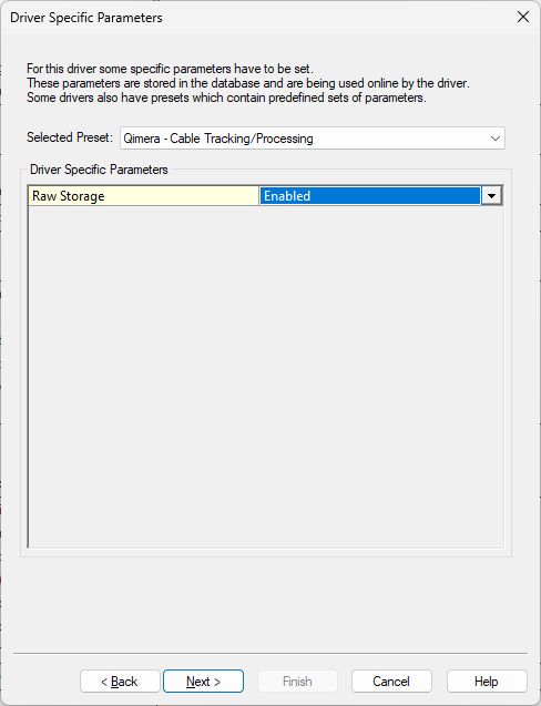
Therefore we added the option to store all unmodified raw data:
-
Raw Storage
Enable the setting so all data from the ARTEMIS will be preserved and ready to use within (that future version of) Qimera. Enabling this setting will increase the file size of each recorded database slightly.
At time of writing this document the cable/tracking processing functionality is not yet available in Qimera.
Third Wizard Page
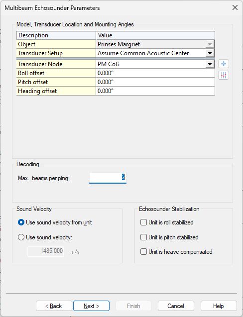
-
Select the correct Transducer Node location.
Normally this will be the reference point of the ARTEMIS frame mounted on the ROV. -
Set the Max. beams per ping: 2
Beam 1 indicates 'top of utility (cable/pipe)'.
Beam 2 indicates 'top of seabed'.
The XYZ values of these two beams will be decoded as follows:
|
Beam |
X |
Y |
Z |
|---|---|---|---|
|
1 |
offset * cos(cable yaw) |
offset * sin(cable yaw) |
depth |
|
2 |
offset * cos(cable yaw) |
offset * sin(cable yaw) |
altitude |
Where
-
offset: is the “Estimated offset from reference point” decoded from message field #8.
-
cable yaw: is the “Estimated yaw of cable or pipeline relative to heading” decoded from message field #15.
-
depth: is the “Estimated depth from reference point to center or top of cable or pipeline, depending on configuration“ decoded from message field # 10.
-
altitude: is the “Altitude“ decoded from message field #17.
Fourth Wizard Page
Just leave all values on this page at their defaults.
Fifth Wizard Page
Just leave all values on this last page at their defaults.
Gyro Compass System
Add a Gyro Compass System to your template setup.
Note that the driver will decode the magnetic heading from message field #22 which source is a magnetic compass inside the Artemis E-Pod.
First Wizard Page
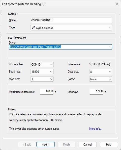
Select driver "SMD Artemis Cable and Pipe Tracker (UTC)".
-
I/O
Use the same interface parameters for all other ‘SMD Artemis Cable and Pipe Tracker’ systems in your template setup.
-
Maximum update rate
Just leave to 0.000 seconds
-
Latency
It is important to set the latency to 1.386 sec.
Second Wizard Page
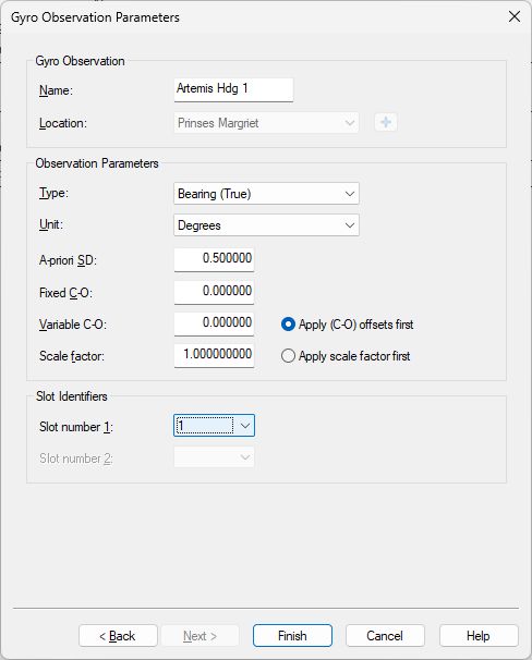
-
Slot
Select for which solution you want to decode the magnetic heading: 1 (Single solution / Aft solution) or 2 (Forward solution)
Pitch Roll and Heave Sensor
Add a Pitch Roll Heave Sensor to your template setup.
The roll and pitch values will be decoded from message fields #23 and #24.
First Wizard Page
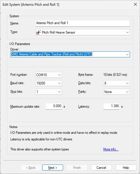
Select driver "SMD Artemis Cable and Pipe Tracker (Roll and Pitch) (UTC)".
-
I/O
Use the same interface parameters for all other ‘SMD Artemis Cable and Pipe Tracker’ systems in your template setup.
-
Maximum update rate
Just leave to 0.000 seconds
-
Latency
It is important to set the latency to 1.386 sec.
Second Wizard Page
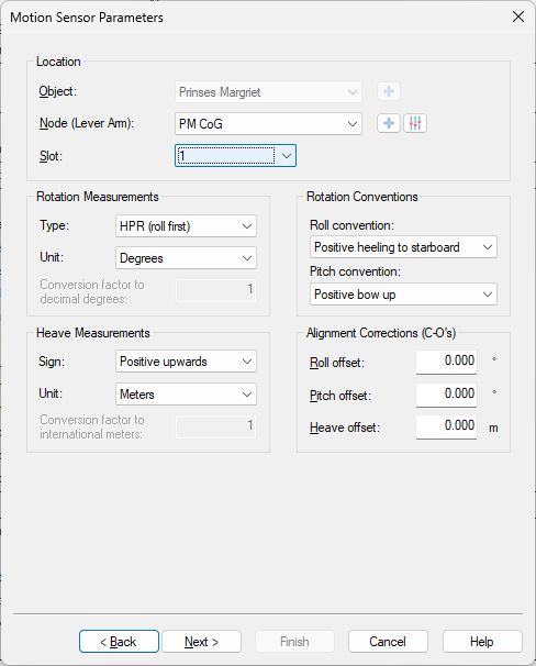
-
Slot
Select for which solution you want to decode the roll and pitch: 1 (Single solution / Aft solution) or 2 (Forward solution)
Third Wizard Page
Just leave all values on this page at their defaults.
USBL System
Add an USBL System to your template setup.
First Wizard Page
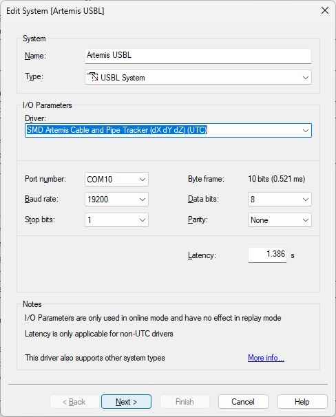
Select driver “SMD Artemis Cable and Pipe Tracker (dX dY dZ) (UTC)”.
-
I/O
Use the same interface parameters for all other ‘SMD Artemis Cable and Pipe Tracker’ systems in your template setup.
-
Latency
It is important to set the latency to 1.386 sec.
Second Wizard Page
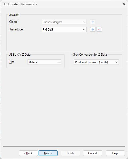
-
Select the correct Transducer Node location.
Normally this will be the reference point of the ARTEMIS frame mounted on the ROV. -
The XYZ value represents the 'top of utility (cable/pipe)' and will be decoded as follows:
|
dX |
dY |
dZ |
|---|---|---|
|
offset * cos(cable yaw) |
offset * sin(cable yaw) |
depth |
Where
-
offset: is the “Estimated offset from reference point” decoded from message field #8.
-
cable yaw: is the “Estimated yaw of cable or pipeline relative to heading” decoded from message field #15.
-
depth: is the “Estimated depth from reference point to center or top of cable or pipeline, depending on configuration“ decoded from message field # 10.
Third Wizard Page
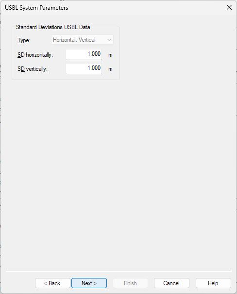
Leave to the defaults
Fourth Wizard Page
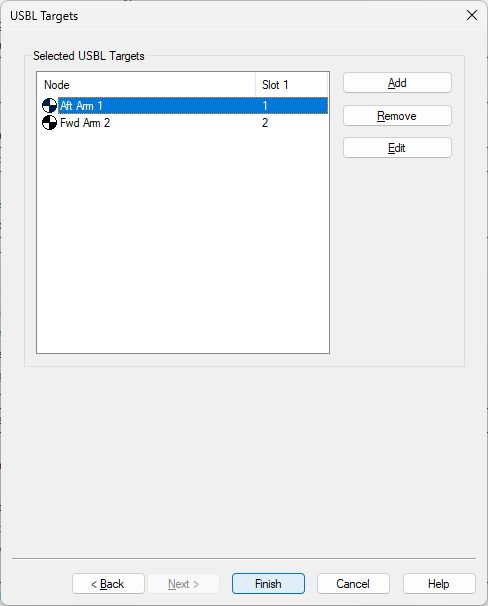
Add the CoG node of the object that represents the ‘top of the pipe/cable’.
Use Slot ‘1' to get the XYZ from the single solution (or aft dual solution) and use Slot '2’ for the forward solution (if available).
Miscellaneous System
Add a Miscellaneous System to your template setup.
Almost every field from the solution message can be decoded as generic observation.
First Wizard Page
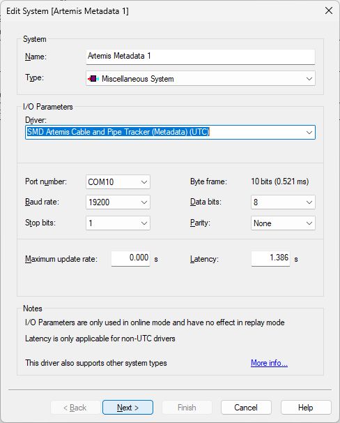
Select driver "SMD Artemis Cable and Pipe Tracker (Metadata) (UTC)"
-
I/O
Use the same interface parameters for all other ‘SMD Artemis Cable and Pipe Tracker’ systems in your template setup.
-
Maximum update rate
Just leave to 0.000 seconds
-
Latency
It is important to set the latency to 1.386 sec.
Second Wizard Page
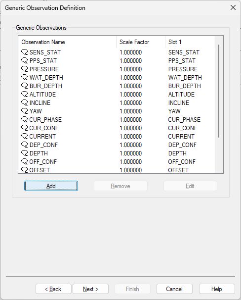
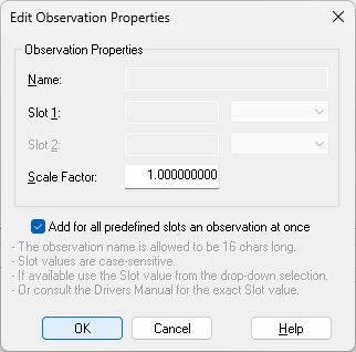
Here you can add up to eighteen unique generic observations that you may want to monitor.
Each generic observation needs a unique Slot Id so the driver knows which field to decode.
It is highly recommended to use the drop-down selection for the correct Slot Id:
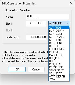
Of course you can change the default name for each observation as long as it doesn't exceed 16 characters.
More convenient may be to use the checkbox to add all observations at once:
Find below this paragraph a table with all possible Slot IDs.
Note that the default Slot name will decode the value from the single or aft dual solution.
Just add '2' to the slot name in order to decode the value from the forward dual solution.
For example if you want to decode the solution status value (2nd field) for the single solution message as a generic observation then use slot name “SOL_STAT”.
And if you want to decode the solution status value for the forward dual solution message then use slot name “SOL_STAT2”.
Third Wizard Page
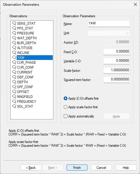
-
Here you can also change the default name of each observation as long as it doesn't exceed 16 characters.
You may leave all parameters at their defaults.
Table Overview Slot Id
|
Slot Id *) |
Generic Observation |
Unit **) |
$IISOL Message Field # |
|---|---|---|---|
|
SOL_STAT |
Solution status
|
Enumerating value, where
|
2 |
|
FREQUENCY |
Solution is based on this signal frequency |
Hz |
6 |
|
MAGFIELD |
Total AC magnetic field at the sensor measuring the largest field |
Decibels |
7 |
|
OFFSET |
Estimated offset from reference point if solution valid, otherwise 0 |
Meters |
8 |
|
OFF_CONF |
Offset confidence if solution valid, otherwise 0 |
Meters |
9 |
|
DEPTH |
Estimated depth from reference point to center or top of cable or pipeline, depending on configuration, if solution valid, otherwise 0 |
Meters |
10 |
|
DEP_CONF |
Depth confidence if solution valid, otherwise 0 |
Meters |
11 |
|
CURRENT |
Estimated current if solution valid, otherwise 0 |
μA |
12 |
|
CUR_CONF |
Current confidence if solution valid, otherwise 0 |
μA |
13 |
|
CUR_PHASE |
Estimated current phase if solution valid, otherwise 0 |
Degrees |
14 |
|
YAW |
Estimated yaw of cable or pipeline relative to heading if solution valid, otherwise 0 |
Degrees |
15 |
|
INCLINE |
Incline of cable or pipeline from horizontal if the incline model type is selected and if solution valid, otherwise 0 |
Degrees |
16 |
|
ALTITUDE |
Altitude, or -9999 if not used |
Meters |
17 |
|
BUR_DEPTH |
Estimated burial depth if solution is valid and altitude is used, otherwise -9999 |
Meters |
18 |
|
WAT_DEPTH |
Water depth, or -9999 if not used |
Meters |
19 |
|
PRESSURE |
Pressure sensor output, or 0 if not used |
|
20 |
|
PPS_STAT |
PPS and ZDA indicator. |
One or two digits, where
|
25 |
|
SENS_STAT |
Sensor status indicator. |
Up to six digits: one digit for each connected sensor, where the first (left-most) digit applies to sensor number 1. The values of the digits can be:
|
26 |
*) Note that the Slot Id is case-sensitive.
*) Add “2” to the Slot Id to decode the field from the forward dual solution message.
**) The original unit from the field value is automatically converted to the unit as mentioned in the table
Qinsy Online
Format Description