Simrad HiPAP Raw (NMEA PSIMSSR) (UTC) - 23
Description
Driver for Simrad HiPAP (High Performance Acoustic Positioning) NMEA Format and to be used to decode USBL X, Y and Z data, relative between HiPAP Transducer and Transponder. The driver supports multiple transducers.
The driver does not decode RAW angles, travel times and using the SVP for ray tracing and to calculate the position of beacons/targets relative to the Transducer
This driver allows the user to decode the "Raw" dX, dY, dZ values relative to the transducer. The values are "Raw" in the sense that they are not corrected for Transducer misalignments (Roll Pitch Yaw) and/or motion (Pitch and Roll), see tab Format for more details.
The priority motion sensor (in Qinsy) is now used for calculating the projection coordinates and transducer misalignment (results from the Qinsy USBL Calibration Utility) can be taken into account.
Note:
When using multiple motion sensors, the USBL transducer misalignment entered is only applicable to the motion sensor used during the acquisition of the USBL calibration data.
When motion sensors are properly aligned with the Qinsy (object/vessel) reference frame and correctly set up for lever arms (to CoG and used Node/Offset point) you should be able to use different motion sensors with the same Transducer misalignment settings.
Please do compare your motion sensors using the QC Report which can be found at: Console - Replay - Export - QC Report.
It can show you the difference in performance and offsets between you motion sensors.
Driver Information
Driver | Simrad HiPAP Raw (NMEA $PSIMSSR Format) | Interface Type | Serial | Driver Class Type | Terminated <CRLF> |
|---|---|---|---|---|---|
Yes and No | Input / Output | Input (one-way) | Executable | DrvQpsTerminated.exe SIMRAD_HPR400_RAW | |
Related Systems |
| ||||
Related Pages | |||||
System Configuration
On this page:
Output to Qinsy

SSBL
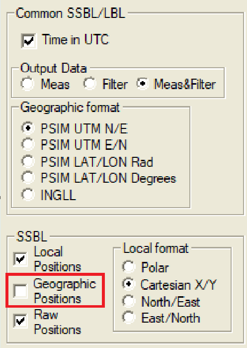
Local Positions
Local Format
Cartesian X/Y
Disable Geographic Positions
Geographic Positions should be disabled, otherwise UTM coördinates will be decoded as coordinates relative to the "Reference Node" (usually the USBL head).
Timing on the HiPAP system
It is advised to use PPS and Time Message on your HiPAP system when using your HiPAP for survey operations to prevent timing issues. To be able to use the PPS Time Synchronization pulse you need to have a special PPS device installed on your HiPAP system.
Some settings of the timing settings your HiPAP:
If you have the PPS and Time Message (ZDA) interfaced to your HiPAP system you will be able to use the following HiPAP drivers in Qinsy:
Simrad HiPAP (NMEA $PSIMSSR Format) (with UTC)
Simrad HiPAP Raw (NMEA $PSIMSSR Format) (with UTC)
Testing
How to change the HiPAP to Simulation Mode:
Password: 1997 (Date when APOS was created/released).
Add beacon B48. This will automatically generate and simulated beacon output.
Database Setup
USBL System
In order to decode USBL XYZ data, relative between HiPAP Transducer and one or more Transponders, add a USBL System to your template database setup, and select driver "Simrad HiPAP Raw (NMEA $PSIMSSR Format)".
Once the system has been added the transponder may be connected by entering the transponder code as slot number.
The following slot numbers are possible:
Slot number | Decoded fields | Example |
|---|---|---|
Tp_code | Td X, Y and Z (Transducer coordinate system) | B63 |
Tp_code + 'V' | Tds X, Y and Z (Vessel coordinate system) | B63V |
Tp_code + 'T' | Td X, Y and Z (Transducer coordinate system) | B63T |
Note that the choice whether to use Vessel coordinate system or Transducer coordinate system affects the USBL setup in the database setup.
The user should only use one coordinate system and it is highly recommended to use Transducer coordinate system.
Defined slot numbers may be changed while on-line: Select the USBL system in the Controller's Computation Setup, and change the USBL Target Slot Field.
ARPA System
In order to show transponder positions as targets in the Navigation Display add an ARPA System to your template.
In the Navigation Display under the Target Layer the targets can be shown and the labels enabled.
This may be used to monitor the performance of the USBL system.
Miscellaneous System
In order to decode Transponder Sensor values add a Miscellaneous system to your template.
Once the system has been added observations need to be added using the correct slot numbers as specified in the table below:
Sensor Type | Observations | Slot number | Example |
|---|---|---|---|
Pressure (Pr) | Pressure in bars | Tp_code + '_PRES' | B63_PRES |
Pressure & Temperature (PT) | Pressure in bars | Tp_code + '_PRES' | B63_PRES |
Temperature in degrees Celsius | Tp_code + '_TEMP' | B63_TEMP | |
Inclination (Ic) | Inclination X in degrees | Tp_code + '_XINC' | B63_XINC |
Inclination Y in degrees | Tp_code + '_YINC' | B63_YINC | |
Compass (Cp) | Heading in degrees | Tp_code + '_COMP' | B63_COMP |
Additional Information for the cable lay environment
Kongsberg has recently been investigating the possibilities to allow for variable draft input into APOS from a vessel mounted draft sensor(s).
This had always as a consequence that there is a serious mismatch in Z between the HiPAP transponder/responder depth values in APOS, shown relative to CoG (this is how they are output to Qinsy) compared to the vessel antenna visualised Z values in APOS (geoidal height of the antenna), the Digiquartz transponder measurements on seafloor/quadrant from APOS and the Digiquartz FF ROV measurements from APOS.
Drivers IO Notes
Option | Meaning |
|---|---|
SIMRAD_HPR400_RAW | NMEA Raw Mode. Decodes $PSIMSSR sentences |
PPS | Instead of using I/O time, use time from datastring (HiPAP is UTC synchronized) |
NOCS | Ignore Checksum |
