
Description
Driver for Kongsberg Simrad EM3002(D) / EM3000(D) / EM1002 Multibeam Echosounder datagrams broadcasted over a network. Driver to be used to decode either the XYZ position of the footprints (X-Y-Z Format) or the raw range and angle (R-Theta Format) from either D, F or f datagram.
The Kongsberg Simrad EM3000(D) has 127 (2 x 127) beams, but only valid beams will be broadcast. The EM3002(D) (an improved EM3000) will have a maximum of 254 (2 x 254) beams. The Qinsy driver will restore invalid beams, by resetting all values to 0, except for quality factor and intensity, which are set to the invalid values according to the EM300x manual, i.e. FF Hex and 7F Hex, respectively.
Driver only uses the UTC time tags from the EM300x datagrams so make sure that the EM300x System is synchronized by GPS PPS and that clock telegrams are transmitted from the EM300x.
Required datagrams for EM3000
The EM3000 must send the following datagrams for correct decoding:
Rho-Theta mode: Recommended Mode
F datagram for raw ranges and angles
D datagram for sampling frequency (not included in F datagram)
C datagram to determine internal EM3000 clock drift and offset
X-Y-Z mode
D datagram for position of footprints
C datagram to determine internal EM3000 clock drift and offset
Rho-Theta mode / from D datagram
"Raw-Data" D datagram for raw ranges, angles and sampling frequency
C datagram to determine internal EM3000 clock drift and offset
Required datagrams for EM3002
The EM3002 must send the following datagrams for correct decoding:
Rho-Theta mode: Recommended Mode
F datagram for raw ranges and angles
C datagram to identify the serial number from the main head
R datagram for raw bathymetry storage
(as of Qinsy version 8 the offset from the clock telegram is no longer used for the EM3002)
X-Y-Z mode
D datagram for position of footprints
C datagram to determine internal EM3002 clock drift and offset
"Raw-Data" D datagram is identical to ordinary D datagram except that some variables like for example the beam depression angle are now attitude-uncompensated launching angles. The EM3000 must be set up to output this special type of D datagrams if "Rho-Theta from D mode" is used.
Only use this mode if F datagrams are not available in the EM3000 software version (earlier versions).
Backscatter, or raw seabed image intensity values, are stored in the S datagram.
If you want to decode the backscatter, see the Simrad EM300x for more details.
Important
Driver will stop updating if no C (clock) datagrams are received for more than 30 seconds. This is done to prevent latency related errors. This limitation is activated as soon as the first clock datagram arrives. So for test purposes it is possible to use this driver without receiving the clock telegram but never use it like this operationally.
EM3002 Only: The clock datagram is used to identify the main transducer head's serial number and therefore the clock message must always be activated. If no clock messages are sent then the driver will not decode any bathymetric data. The clock message will only be sent when the Kongsberg PU (Processing unit) receives a ZDA string on its serial port. The clock offset derived from the C telegram is no longer applied in Qinsy 8.
Driver Information
|
Driver |
Kongsberg EM3002
|
Interface Type |
UDP/UP- Client |
Driver Class Type |
|
|---|---|---|---|---|---|
|
Yes |
Input / Output |
Input |
Executable |
DrvSimradEM3000.exe |
|
|
Related Systems |
|
||||
|
Related Pages |
|||||
Decoding Notes
-
Driver will always output the decoded maximum number of beams (with a maximum of 127, EM3002 254). Invalid beams are restored to the MBE data buffer, with all values set to 0, except quality factor (FFh) and intensity (7Fh).
-
Beam Intensity values (backscatter) that are stored in the datagram have a range from -128 to 126 (0.5 dB steps). These values are converted to Qinsy Intensity range that runs from 0 to 255.
-
The decoded Quality Indicator (QI) can be considered a figure with a range between 0 and 64, where 0 stands for best quality.
Actually the value from the EM3000 is a combination of flags and values but inside the driver this is interpreted to a range between 0 (= best quality) and 64 (= worst quality) for valid beams and 127 for the invalid beams. For amplitude bottom tracked beams this value stands for the used number of samples while for phase bottom tracked beams this value stands for the "fit".
Rho-Theta Only:
The Beam angles that are reported in the F telegrams are valid in the receive array and not in the acoustic center. Qinsy assumes the beam angle and the range to be valid at the acoustic center. This non-conformity will result in small depth independent depth errors at the outer beams. The driver will correct the reported beam angles so they are valid for the acoustic center. By default this option is enabled but it can be disabled if necessary through the registry key: "Use beam angle wrt acoustic center correction", 0 = disabled, 1= enabled. QPS advises however to keep this enabled.
System Configuration
EM3000Compact
The Simrad PU has the capability to send data to three user-definable UDP ports. Please set up as many ports as required by the interfacing to Qinsy (see Database Setup below).
EM3000
The workstation with Simrad's Merlin software running on it, sends the data to Qinsy. In order to activate the transmission, one should do the following:
In the file $HOME/DPC.addresses.`hostname`, just below the line "#user_start" add a line using the following format:
Format
NAME IPADDR PORTNO TELEGRAMS
Format Example
Qinsy 192.1.1.2 2101 C D F
The IP-address and port number are for the machine to which these datagrams are to be sent. The letters following the port number are an indication of the datagrams, which are to be output on this port.
In order to be able to test the network connection it is advised to add a line to the 'host' file using the following format:
Format
IPADDR HOSTNAME
Format Example
192.1.1.2 qps
This allows the user to use the 'ping qps' command to test the network connection.
EM3000D
The workstation with Simrad's Merlin software running on it, sends the data to Qinsy. In order to activate the transmission, one should do the following:
In the file $HOME/DPC.addresses.`hostname`, just below the line "#user_start" add two lines using the following format:
Format
NAME IPADDR PORTNO TELEGRAMS
Format Example
Qinsy1     192.1.1.2  2101           C D F
Qinsy2     192.1.1.2  2102           C D F
The IP-address and port number are for the machine to which these datagrams are to be sent. The letters following the port number are an indication of the datagrams, which are to be output on this port.
In order to be able to test the network connection it is advised to add a line to the 'host' file using:
Format
IPADDR HOSTNAME
Format Example
192.1.1.2 qps
This allows the user to use the 'ping qps' command to test the network connection.
Important: In all these examples the IPADDR and PORTNO fields are examples and might require different values based on the actual network configuration.
Setting up ethernet (port 1999 should not be used if same subnet is used for both Qinsy and EM300X!!!!)
EM3002(D)
This echosounder uses pitch compensation and therefore it requires the serial input of an attitude sensor (EM3000 binary format).
If no attitude sensor is connected then pitch compensation is not applied.
Interfacing Notes
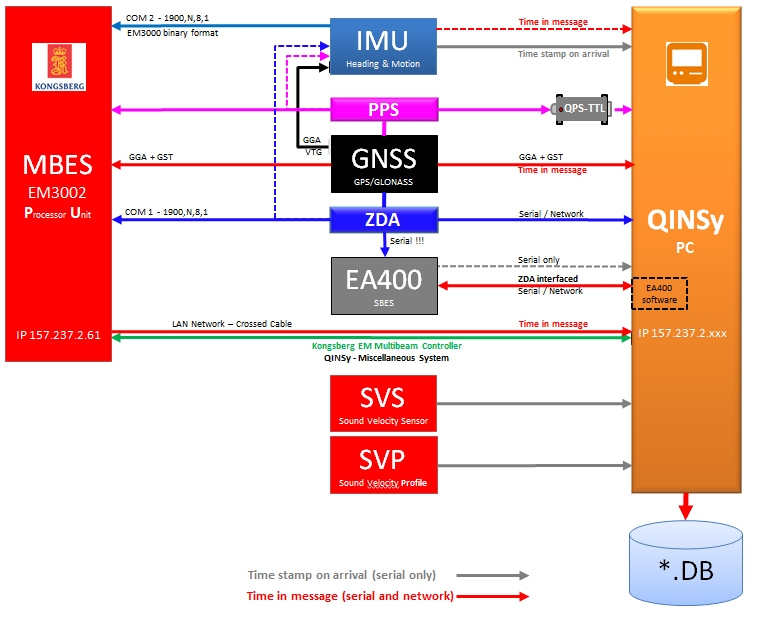
Single Head Setup Example (PU controlled by Qinsy EM Controller Driver)
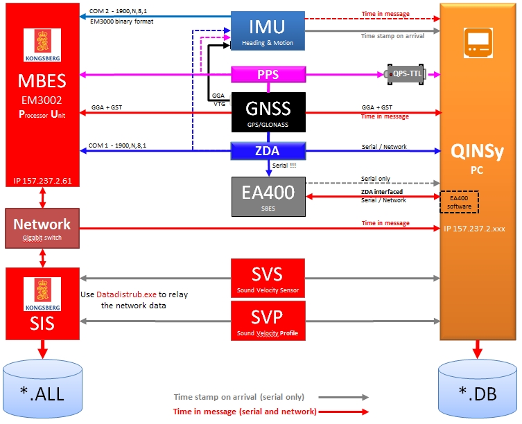
Single Head Setup Example (PU controlled by SIS)
Sound Velocity
In order to obtain valid bathymetric results, the multibeam system and Qinsy need valid speed of sound information. All types of multibeam systems require the sound velocity profile but systems that utilize beam steering, usually systems with a flat array transducer, require the sound velocity at the head for the beam angle correction (beam steering) too.
When using a flat array transducer multibeam system like the EM3000/EM3002 the sound velocity at the transducer can be applied in three different ways:
-
Real-time sound velocity fed into Multibeam Unit
If the sound velocity can be interfaced real-time into the multibeam system then the beam angles that are reported by the system to Qinsy are correct and no further angle correction is required. This is an option when the Echosounder is controlled from Kongsberg SIS software. SIS will interface the sensor and send the Sound Velocity information via the network to the PU. -
Real-time sound velocity fed in Qinsy
This requires the sound velocity sensor to be interfaced to Qinsy. Qinsy can then correct the launch angles before the final DTM points are calculated. Launch angle correction can be calculated by comparing the used sound velocity (reported by the multibeam system) with the actually measured sound velocity. The approximate sound velocity should be entered into the EM3000 Controller program/ SIS/Kongsberg EM controller driver for correct pitch adjustments. -
No real time sound velocity
Qinsy only supports beam angle corrections when a sound velocity probe is interfaced. This implicates that the sound velocity used by the multibeam system must be accurate (up to =/- 2m/s) or else the multibeam results will start to deteriorate, ultimately noticeable as frowns or smiles. This means that the correct sound velocity value (as obtained from the sound speed profile) must be entered into the multibeam controller software. In the case of EM3000/3002 this is either the EM3000 Controller program or the SIS program or the Qinsy EM control driver. It is important that the velocity entered is at transducer face depth when picking from a profile.
Time Synchronization (formerly PPS)
In order to get a correct time synchronization between Qinsy, the EM300x and the GPS receiver connect BNC cable with Time Synchronization pulse from a GPS receiver to both the EM300x system and the Qinsy Time Synchronization adaptor (Use T-splitter).
Set switch of QPS Time Synchronization Adapter to the active trigger flank of the Time Synchronization signal. Refer to the GPS Manufacturer manual to see which is the active flank.
Connect serial cable with GPZDA NMEA message from GPS receiver to the Qinsy computer.
Create an NMEA ZDA output driver in Qinsy Database Setup (as shown below)
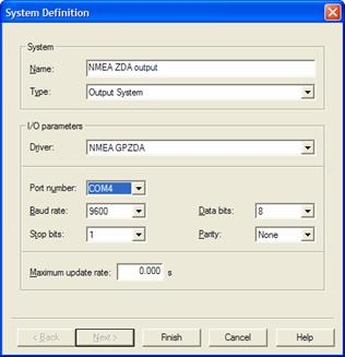
Connect a serial cable from the Qinsy computer to the EM300x PU for the output of the NMEA ZDA message.
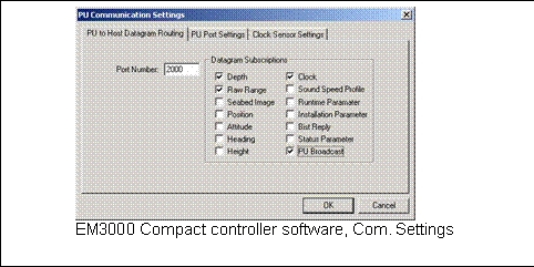
EM3000 Controller/ SIS
Set up correct clock settings, for example see EM3000 controller settings below:
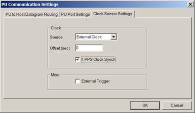
Note that choosing the valid flank is not very relevant for very short PPS pulses (e.g. Trimble) but becomes utterly important when it comes from a Sercel/Dassault/Thales receiver or similar. This pulse is half a second long so when the wrong active flank is chosen timing can be off by half a second.
Note: The EM3000 PU triggers only to the falling flank of the PPS signal. The EM3002 PU is programmeable to rising or falling (only by Kongsberg Simrad engineers).
Acoustic Center of EM3000/EM3002
The Acoustic center is the point for which the node position must be entered into the Qinsy database. The EM3000 manuals will mention the acoustic center to be in the geometric center of the transducer face but this is not exactly true: it is slightly offset. The drawing below shows a schematic overview of the acoustic center.
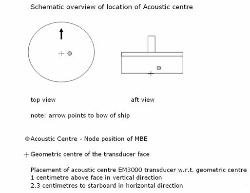
For a dual head system with 40° roll, 0° pitch and 0° heading mounting angles the corrections are:
Port Head: Acoustic center is 2.4 centimeters starboard and 0.7 centimeters below Geometric Center.
Starboard Head: Acoustic Center is 1.1 centimeters starboard and 2.2 centimeters above Geometric Center.
Database Setup
For every EM3000 related multibeam or sidescan system, Qinsy requires the data to be sent to a unique port Number:
|
EM3000 Setup |
Required ports to interface to Qinsy |
|---|---|
|
Single head multibeam |
1 |
|
Single head multibeam + sidescan |
2 |
|
Dual head multibeam |
2 |
|
Dual head multibeam + sidescan |
3 |
Echosounder stabilization
The echosounder Stabilization is greyed out in the Database Setup because the output string already contains the information about whether the systems is stabilized or not.
Transducer Beam Steering Angle
For the TPU calculation the minimum steering angle can be defined. The Simrad transducer is flat so the angle is 0°.
EM 300x (one transducer)
See description in Database Setup, except that the present Qinsy driver is only meant for datagrams broadcast over a network, so instead of entering serial port parameters, the port number has to be entered.
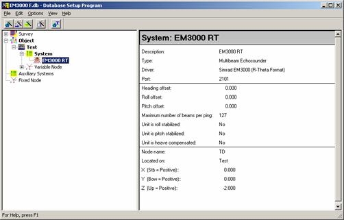
DbSetup example for Simrad 3000Compact system.
EM3000D Dual Head (two transducers)
An EM3000D system must be configured in Database Setup as two single EM3000 Multibeam systems that have a node position and unique mounting angles per transducer . Choose one of the "Head II" systems to decode the beam data from the second transducer. In normal mode, the driver decodes the first 127 beams (1-127) from the telegrams, while with Head II option enabled, it decodes the second 127 beams (128-254). In a normal configuration, the first 127 beams are located on the PORT transducer, the second 127 beams on the STARBOARD transducer. The Port transducer will have a positive mounting roll offset (+30 to +40°). Starboard transducer must have a negative roll offset (-30° to -40°)
It is advised to assign different port numbers for port and starboard heads.
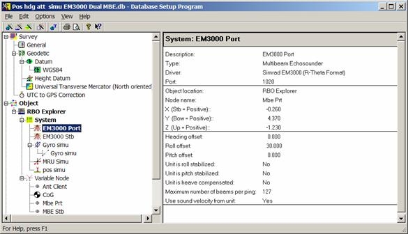
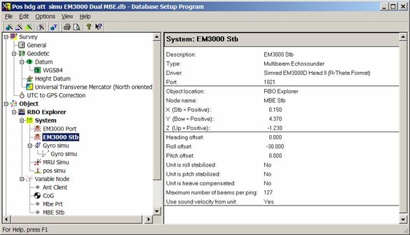
DbSetup example for Simrad 3000D Dual Head system.
EM3002D Dual Head (two transducers)
The setup for the EM3002D works similar to the EM3000D. Only the beam numbers are different. Each head has 254 beams starting with 1 at the port side of the matching transducer.
Raw datagram storage
Qinsy can optionally store the raw incoming datagrams into the database for XTF export or for further processing in Fledermaus. In order to activate this make sure to select the driver appropriate Driver Specfic Settings (see below). Only a limited number of packets will be stored: F or f, D and R (Runtime).
Drivers Specific Settings
In DbSetup for this driver some driver specific settings can be entered. These supersede the command line parameters.
The following settings can be selected:
|
Setting |
Option (bold=default) |
Description |
|---|---|---|
|
Raw Bathymetry Storage* |
Disabled/Enabled |
When Enabled the Raw (original) Bathymetry packets(e.g. f) and the Runtime Settings (R) are stored in the database for usage in Fledermaus. |
|
Raw Seabed Image Storage** |
Disabled/Enabled |
When Enabled the Seabed Image (S) is stored in the database for usage in Fledermaus. |
|
Water Column Usage |
Disabled/Enabled |
When Enable the Water column data is decoded by the Driver. The STORAGE of the water column is activated with a setting in the Controller Session Setup - Database page. |
*) The decoded raw multibeam data is also stored so by enabling Raw Bathymetry Storage the Database will grow larger.
**) In the past Seabed Image data were stored as part of the sidescan system data but this is now part of the multibeam data.
Online
When online, select the "Echosounder settings" option from the "Settings" menu to define the online blocking and filtering of the multibeam echosounder data.
Use a Raw Multibeam Display to show raw data and a Swath System Display to show the corrected scans.
Kongsberg Controller
The EM3000D systems does not work with the Kongsberg Multibeam Controller available in Qinsy, instead it will control EM3002 and EM2040 single and dual head systems.
Drivers IO Notes
Command line parameter "0" denotes the R-Theta format from F/f datagram, "1" denotes the X-Z format and "2" the R-Theta Format from D datagram. If the driver is started without the parameter it will start by default in Rho-Theta mode.
"DII" means that instead of decoding beam 1-127, the driver decodes beam 128-254.
"EM1002" indicates that the driver has to deal with an EM1002 echo sounder.