
Description
Driver to decode data from a Sense MARINE Pipe and Cable Tracker
Driver Information
|
Driver |
Sense MARINE Pipe and Cable Tracker |
Interface Type |
Serial |
Driver Class Type |
Terminated |
|---|---|---|---|---|---|
|
No |
Input / Output |
Input |
Executable |
DrvTSS350.exe |
|
|
Related Systems |
|
||||
|
Related Pages |
|
||||
Decoding Notes
There is no timing information in the data message, so data is time-stamped when received at the COMport.
-
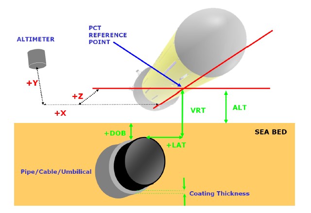
The lateral offset (LAT) is measured from the PCT reference point to the top of the conductive part of the target (pipe/cable). The reading is always with respect to the forward facing direction of the ROV, i.e. positive when target is to starboard and negative when the target is to port of the of the PCT reference point.
-
The vertical range to target (VRT) is the distance between the PCT reference point and the top of the conductive part of the target (pipe/cable) minus the target coating thickness. As a result of the target calibration process, the target coating thickness may be set to 0.0 depending on the type of target.
-
The Altitude (ALT) field contains altitude information from either an altimeter if fitted or a fixed height if set.
-
The target depth of burial (DOB) is defined as: VRT minus ALT. The value is positive when the target (pipe/cable) is covered and negative when exposed.
Database Setup
-
In order to detect the top of the pipe (or cable) and the seabed above (pipe buried) or below the pipe (freespan), add a Multibeam system to your template setup and select driver "Sense MARINE Pipe and Cable Tracker (PCT)".
Set the correct IO parameters, leave the maximum update rate and latency at zero and press Next for the 2nd wizard page.
The selected Transducer Node must be the PCT reference point, as described in the Decoding Notes above.
Set the maximum beams per ping to 2:
-
-
Beam 1 will contain the detected top of the pipe
-
Beam 2 will contain the seabed, above or below the detected pipe location.
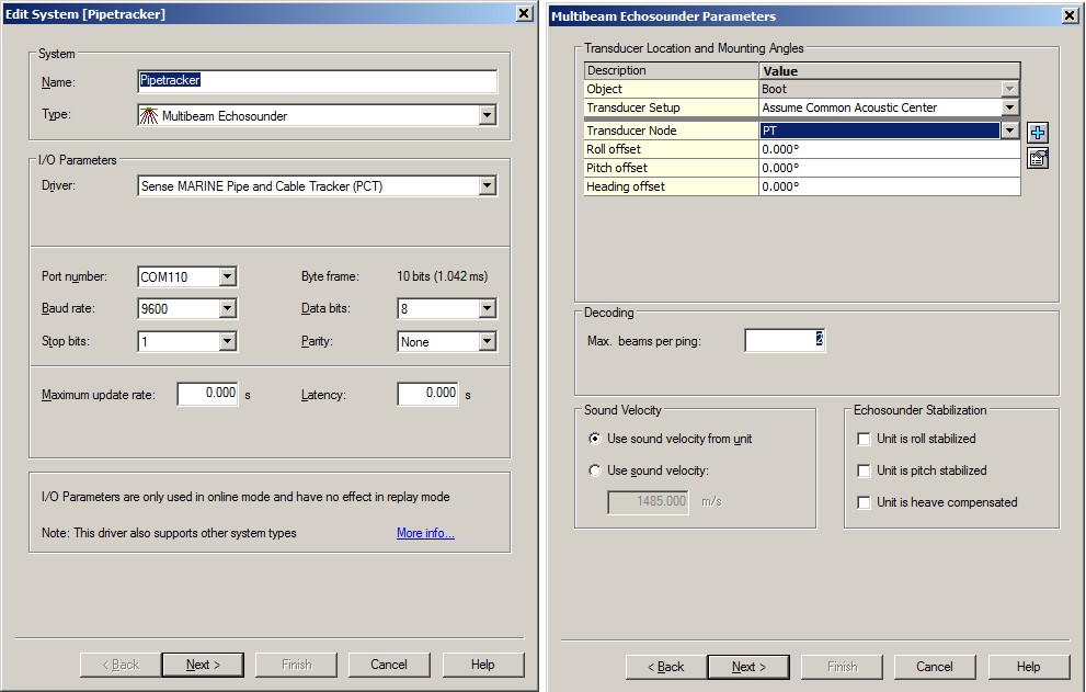
Leave all other parameter values at their defaults. -
License
For this system Qinsy Multibeam support must be enabled on your license.
-
In order to decode the depth of burial (DOB), add a Miscellaneous system and select driver "Sense MARINE Pipe and Cable Tracker (Depth of Burial)".
Use the same IO parameters as above and press Next.
On the 2nd wizard page, add only one generic observation, name it e.g. "DOB" and set Slot 1 to "0".
The decoded value will be in meters.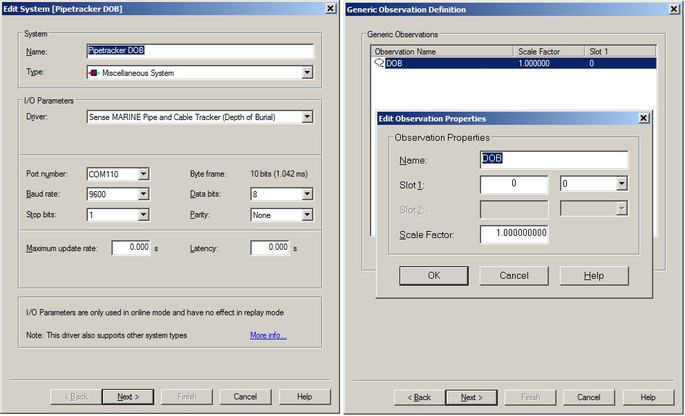
-
In order to decode the altitude (ALT) value, add an Underwater Sensor system and select driver "Sense MARINE Pipe and Cable Tracker (Altitude)".
Use the same IO parameters as above and press Next.
On the 2nd wizard page, add one observation of type 'ROV Altitude'. Do not add other types of observations.
Select for the At Node the PCT reference point, as described in the Decoding Notes tab page.
On the last wizard page, set the unit for this observation to 'meters'.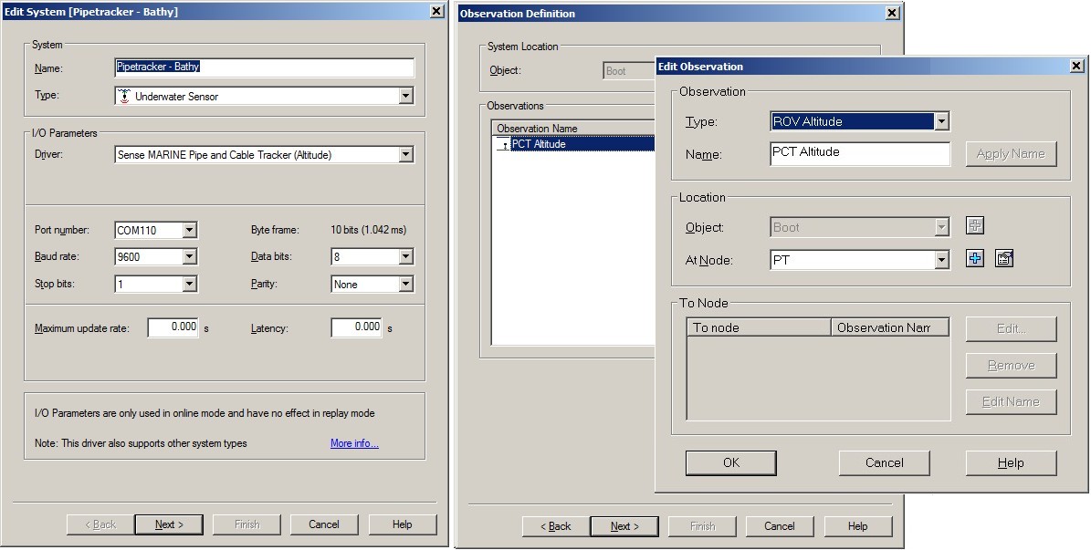
Online
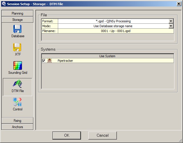
Detected pipe information can be stored in a DTM file for further processing:
Open the Controller's Session Setup, Storage, DTM File dialog, select your DTM File format and make sure that the pipetracker system is enabled. If you do not see the pipetracker system, please enable the system first in the Computation Setup.
You may use a Swath System Display to visualize the detected pipe:
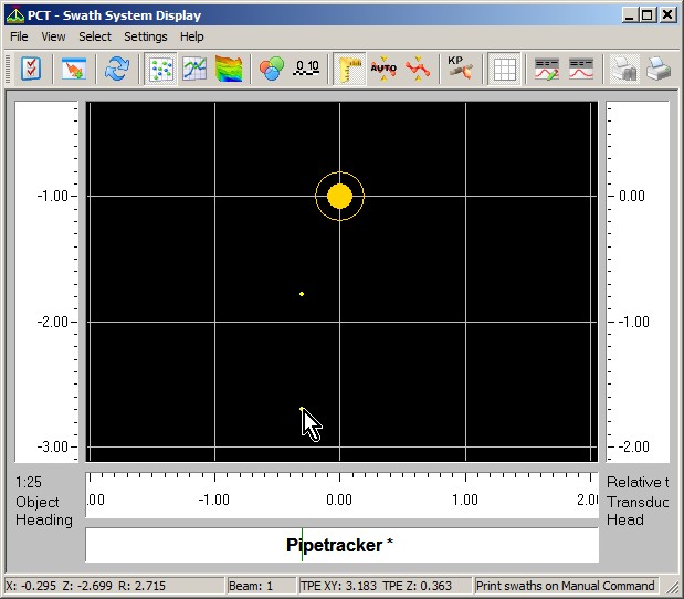
Two beams are plotted under the transducer node (PCT reference point). Hover the mouse cursor above a beam dot to get information in the status bar at the bottom of the dialog.
Beam 1 represents the top of the detected target (pipe or cable) and beam 2 represents the seabed surface. So in the above example you will notice that the target is buried for almost one meter (0.918m to be exact).
Use a Generic Display to show the numeric values of the detected pipe:
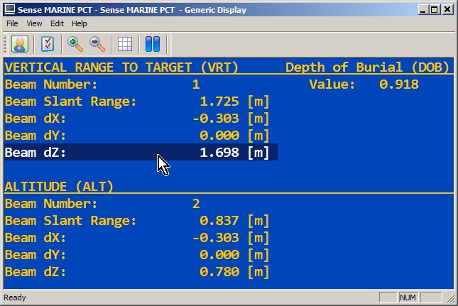
Item Beam dX represents the lateral offset of the target, and item Beam dZ represents the vertical distance to the detected target (beam 1) or to the seabed (beam 2). Note that item Beam dY is always zero.
As an example you may download Generic Display Layout XML from this link.
(Use right-mouse Save Link As.. option, then copy the file into the current Project's \Settings\Display folder and open it using a new Generic Display. Do not forget to select the correct systems and observations).