
Description
Driver decodes sidescan and multibeam data from the SEA Swath Plus sonar system. Driver Interfaces to the SEA Swath plus software (swath.exe) running in the background on the same PC as Qinsy. The SEA Swath Plus software connects to the Sonar's (TEM) hardware via USB. The Qinsy driver will connect via TCP/IP to the SEA Swath Plus software as a client. IP and port number should be configured properly in Qinsy and in Swath Plus. IP Number should be set to 127.0.0.1.
Qinsy can also be used to change the settings of the sonar from Qinsy.
Driver Information
|
Driver |
SEA Swath Plus |
Interface Type |
TCP-IP |
Driver Class Type |
|
|---|---|---|---|---|---|
|
Yes |
Input / Output |
Input |
Executable |
DrvSEASwathPlus.exe |
|
|
Related Systems |
|
||||
|
Related Pages |
|
||||
Decoding Notes
Every sample as found in the packet will be decoded as a beam with an amplitude, range, beam angle and quality. The Swath Plus software pre-processes the samples with a number of basic filters. The outcome of the filters is encoded in the quality flag. Accepted data will have a quality of zero, any sample that did not pass the filter will have a non-zero value. Quality can hence be used within Qinsy to block out the invalid samples. In order to save cpu load on the Qinsy machine it is possible to set up the SEA Swath program to remove the rejected points before transmitting them to Qinsy.
The beam angle is converted to Qinsy convention inside the driver. This process requires the driver to know the orientation of the transducer (either port or starboard) which is forwarded by the Swath plus software.
If Qinsy is interfaced to a PPS system then it will use the decoded ping time from the received PARSED_PING_DATA packet, in other cases it will use the arrival time of the TCP packet. Note that in order to use the decoded ping time the Sonar hardware should be synchronized to PPS too.
Note that sidecan data is only decoded for Transducer 1 and Transducer 2.
Interfacing Notes
Network TCP/IP interface is used. Qinsy driver takes client role, swath.exe as server.
System Configuration
The Swath Plus program swath.exe should run on the same computer as Qinsy. The program is to run in a mode with a minimum of processing and displays so it will consume a minimum of CPU load. Swath.exe connects to the sonar hardware via USB and forwards the pre-processed data to Qinsy. The Qinsy driver automatically connects to the swath.exe program on startup. The driver will forward its last known settings (retrieved from registry) after it is connected to the sonar. For more details on how to set up the swath.exe program contact SEA. See below for a screen capture of the swath.exe program. The status display of the program shows if Qinsy connected correctly to it. Every time a sonar setting is changed within Qinsy the settings will be forwarded to the swath.exe, its status display will show "CMS command read". Note that the Qinsy driver will reconnect every 20 seconds if no data is sent by the swath.exe program.
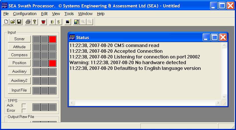
Figure: Screen capture of Swath Plus software. The Status display shows that Qinsy connected to it and that a Command message is accepted.
Setup the Swath's TCP/IP Socket(s)
The Sea Swath program TCP/IP socket(s) need to be set up so the Qinsy driver can connect to it. The program contains two sockets for the purpose of transferring data to third party programs. Usually the first socket is used for the multibeam data and the second for the sidescan data. This way different filtering setups can be utilized, e.g. for sidescan you want to keep all the samples whereas for multibeam some form of down sampling (footprint reduction) is often used.
In order to activate the socket the following steps should be carried out:
-Press the Socket 1/Socket 2 button, this will show the socket setup dialog.
-Check the Enable button.
-Select Server and Send radio buttons.
-IP address should be 127.0.0.1 when running both programs on the same PC (advised) or the IP number of the Qinsy PC.
-Port Number is user defined but should be the same as selected in DbSetup for the multibeam systems (or sidescan system), a good value is 5001 for the first socket and 5002 for the second socket.
-Data Format should be SWATHPlus Parsed for both sockets.
-Select the Parsed Data Properties to set up the filtering for the data, here you can also set up a form of point reduction if required (Down sampling Tab).
-Suppress processing... and Block pinging... checkboxes may be left unchecked.
Database Setup
Enable the checkbox "Control System From Qinsy" in DbSetup system setup page. This will show an extra Tab page in the Controller's Echosounder Settings Dialog.
The driver will store the last entered settings in the registry when Qinsy closes. On Restart of Qinsy the last used settings are retrieved from the registry and sent to the sonar.
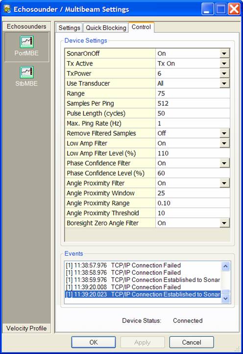
Figure: Screen capture of Controller's Echosounder Settings dialog.
Single Head System:
Add new multibeam system to the template, select Driver "SEA Swath Plus". Set IP number to 127.0.0.1. and port number to the number as setup in the Sea Swath program's output socket setup. Enable the checkbox "Control System From Qinsy". Slot number on next page should be set to 1.
Dual Head System:
Add two multibeam systems, select the same driver for both systems, Driver "SEA Swath Plus", IP number also to 127.0.0.1. For both drivers select the same port. Enable the checkbox "Control System From Qinsy" for both systems. For the port head Slot number 1 is to be entered, for the starboard head Slot number 2.
Triple Head System:
Same as for a dual head system but now also select a third multibeam system with same parameters as the other 2 except the Slot number should now be set to 3.
Maximum number of beams in one ping should be set to the maximum number of samples that are used, can be configured in the Echosounder control Tab in Controller's Echosounder Settings dialog (line "Samples Per Ping"). Some default figures are 1024, 2056, 4068.
Transducer Mounting angles:
If the transducers are mounted with a depression angle of 30° then the roll offsets will be typically: +60° for a port head and -60° and for the starboard head and pitch and heading are around 0. For a third forward mounted head the mounting angles are estimated to be Pitch: +30°, Roll -60°, Heading -90°.
Sound velocity correction:
If a sound velocity probe is interfaced into Qinsy and not into the Swath Plus software then it may be useful to select the sound velocity observation for beam angles correction on the last page of the multibeam system wizard. This enables the automatic correction of the reported beam angles because the Swath Plus software uses the wrong sound velocity.
If you also want to decode sidescan data then add a Sidescan system to the template. Select Driver "SEA Swath Plus". Setup same IP number as the multibeam system(s). Selected the appropriate port number as setup in the Swath software. Add two channels, first port, second starboard, no further settings are required. If only one transducer is used then only add one channel.
Online
Qinsy beam reduction
A smart beam reduction algorithm is introduced to cope with the great number of samples that are reported by this sonar system. Since every sample is translated in the driver to a beam, the CPU load caused by processing beam data from an interferometric system can become rather high. If the CPU load generated by the multibeamer.exe components becomes too high then the max. beam count reduction should be enabled. Go to "Echosounder settings" dialog, for interferometric systems the line "Max. beam count" is added to the reduction options. This works independent of the other reduction methods. Typically enable this option and select 500 here. Depending on range/sound velocity profile point count and resulting CPU load the number of kept beams may be increased or decreased.
Note that many users already set up the beam reduction in the Swath Plus software, of course the beam reduction in Qinsy is not utilized then.
System Control
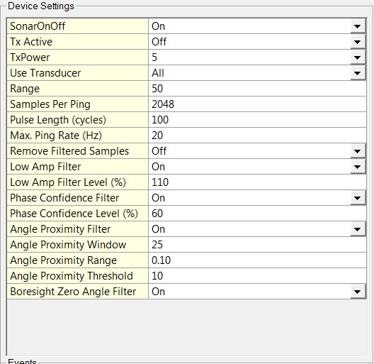
The operating settings of the sonar are modified through the Echosounder Settings dialog control Tab of the controller. The following settings can be modified:
|
Setting |
Description |
|---|---|
|
SonarOnOff |
Enables and disables data acquisition. |
|
TxActive |
Enables and disables sonar transmission. |
|
TxPower |
Select power level from drop down list. Min = 0, Max = 15
|
|
Use Transducer |
Select number from drop down list. Enter Min = 1, Max = 15 (All) Up to 4 channels active at any one instant (selected from any number of connected Transducer Electronic Modules -TEMs). |
|
Range |
Enter Min = 1, Max = 65535 in meters Called the Ping Range in Swath Plus software. This controls how long the sonar listens for signals and hence the maximum range of the ping. Swath Plus allows this range to be set in meters. The corresponding Pulse Repetition Frequency is calculated in the software and used in data acquisition.
|
|
Samples per Ping |
Enter Min = 512, Max = 65535
|
|
Pulse Length (cycles) |
Enter Min = 8, Max = 200
|
|
Max. Ping Rate (Hz) |
Enter Min = 1, Max = 40
The time taken for a ping cycle is that for a round trip from the transducers, to the farthest range and back again. For example, a 150 metre ping takes 0.2 seconds when the speed of sound in water is about 1500 meters per second. This gives a Pulse Repetition Frequency (or Ping Rate) of 1 / 0.2 = 5 per second (or Hertz). |
|
Remove Filtered Samples |
Either On = Remove or Off = Don't remove.
Note that Sidescan data requires all of the raw data to provide good images. the Bathyswath Swath processor application acts as the interface to the Bathyswath hardware, and performs some initial processing and filtering before sending the data to the third-party process. The data that results from this process is as raw as possible whilst maintaining a consistent range-and-angle data format. This format is known as the “Parsed Data” format. |
|
Low Amp Filter |
Either On or Off. This filter assumes that measurements with a low amplitude are either not a return from the seabed at all, or from a distant point, where signal-to-noise ratio is poor. This filter rejects samples whose amplitude falls below a threshold value. The threshold value is maintained automatically by the SWATHplus processing using a history of data. The threshold is derived by SWATHplus finding the section of the bathymetric profile that has the lowest amplitude. The samples within this section are then sorted by amplitude and the lowest are used for an average. This average is, in turn, used to generate a "running average” that builds up with time. Setting the Low Amplitude Filter Level shifts the threshold value up and down further. This has the effect of rejecting more or less of the low amplitude data. |
|
Low Amp Filter Level (%) |
Usually set to 110% There are two modes to this figure: one used for entries up to 600, and one for higher values. This field refers to entries less than 600. A number between 1 and 600 is read as a percentage adjustment of the “running average” level. It adjusts the level calculated by the running average described above up or down. For example ‘120’ sets the level 20% higher than the running average, and ‘80’ sets it 20% lower. A number above 600 is read as an absolute value, and sets the filter level to the number set. |
|
Phase Confidence Filter |
Either On or Off. SWATHplus calculates depths by examining the phases of the returning sonar signals at the transducers. This filter assumes that a given angle of return will provide patterns of phase response that are self-consistent. The angle can be calculated in several different ways from the measured phases. If the different ways give wildly different angles, then the measurement sample is probably noise. This filter uses the fact that the elevation angle at the transducer can be derived from the phases in several ways. Having calculated the angle in one way, the reliability of the conversion can be measured by comparing the phases in the sample with those that would have been needed to create the angle in other ways. If these phases are too far from these theoretical values, the sample is rejected. |
|
Phase Confidence Level (%) |
Enter Min = 0, Max = 100
|
|
Angle Proximity Filter |
Either On or Off. This filter compares the angle values for a sample with its neighbours (within the ping). If too few of the neighbours are close to the sample in angle the sample is rejected. This filter is not applied close to nadir because angle varies rapidly with slant range in that region. The filter is applied at angles above Minimum Elevation . This is measured relative to horizontal. Therefore, -90 degrees is directly below the transducers, and -120 degrees (the default) is 30 degrees further round, which is the limit of view of a transducer pointing downwards by 30 degrees. |
|
Angle Proximity Window |
Enter Min = 3, Max = 250
|
|
Angle Proximity Range |
Enter Min = 0, Max = 1.0 (in hundredths of sine).
|
|
Angle Proximity Threshold |
Enter Min = 2, Max = 250
|
|
Boresight Zero Angle Filter |
Either On or Off. The boresight filter removes all data that is at, or close to, the normal to each transducer. That is, signals coming straight in to the transducer face. This is useful when there is strong external noise, because such noise signals usually appear the same on all the transducer channels (i.e., they are “common mode” noise). Such signals are interpreted as angles close to the normal. Such noise signals can be removed with this filter. |
Additional Information
System History
Around 1985, research at Bath University showed that interferometric swath bathymetry is a practical way of measuring seabed depth. A spin-off company (Bathymetrics) was launched to exploit this, and Bathyscan (1987), was possibly the world’s first commercially-available interferometric swath sonar system. Bathymetrics became Submetrix, and produced ISIS 300, then ISIS 100, and Submetrix 2000. The technology was then acquired by Systems Engineering & Assessment Ltd. (SEA) and the system was renamed SWATHplus.
In August 2012, ITER took over SWATHplus activity and renamed the systems as Bathyswath. In November 2013 a dedicated company, ITER Systems, was specifically created for the manufacturing and the marketing of Bathyswath systems.
For more information refer to SEA website: http://www.sea.co.uk/swathplus.aspx?nav=products.