Description
Driver for Reson Seabat 81xx & 900x series Multibeam Echosounders using a network UDP connection.
The driver will automatically detect the input format, but will only decode R_THETA or RI_THETA packets and SNP0/SNP1 packets.
Driver Information
|
Driver |
Reson Seabat 81xx-900x (Network) |
Interface Type |
UDP/IP Client |
Driver Class Type |
Counted |
|---|---|---|---|---|---|
|
Yes |
Input / Output |
Input |
Executable |
DrvSeabatSocket.exe |
|
|
Related Systems |
|||||
|
Related Pages |
|
||||
Decoding Notes
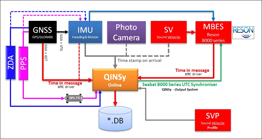
The time tag from the data packets is used (if it is not zero) if the Reson Seabat driver is a network driver. Therefore it is highly recommended to synchronize the times of the Qinsy and Seabat systems by adding the output driver "Seabat 8000 Series UTC Synchroniser" to the database. If the Qinsy online setup includes a PPS system, then the time tag will be truly UTC.
Note that checksum calculation is always enabled, this implicates that packets with invalid checksums will be rejected.
In the past the snippets were decoded as part of the sidescan system data but this is now part of multibeam system data.
Brightness and Colinearity flags are decoded and used by Qinsy:
|
Bit |
Description |
1 = |
0 = |
|
0 |
Brightness |
1 = pass |
0 = fail |
|
1 |
Colinearity |
1 = pass |
0 = fail |
|
2 |
Bottom Detect Process (Magnitude) |
1 = used |
0 = not used |
|
3 |
Bottom Detect Process (Phase) |
1 = used |
0 = not used |
This translates into the following Quality indicators:
|
binary figures |
as shown in Qinsy |
BDP - Phase |
BDP - Magnitude |
Colinearity |
Brightness |
|---|---|---|---|---|---|
|
0000 |
0 |
|
|
|
|
|
0001 |
1 |
|
|
|
|
|
0010 |
2 |
|
|
|
|
|
0011 |
3 |
|
|
|
|
|
0100 |
4 |
|
|
|
|
|
0101 |
5 |
|
|
|
|
|
0110 |
6 |
|
|
|
|
|
0111 |
7 |
|
|
|
|
|
1000 |
8 |
|
|
|
|
|
1001 |
9 |
|
|
|
|
|
1010 |
10 |
|
|
|
|
|
1011 |
11 |
|
|
|
|
|
1100 |
12 |
|
|
|
|
|
1101 |
13 |
|
|
|
|
|
1110 |
14 |
|
|
|
|
|
1111 |
15 |
|
|
|
|
System Configuration
-
Sound Velocity
You can interface the SV with Qinsy, but it is not necessary and it will not be used by Qinsy to supply the 8125 with Sound Velocity observations.
Beside a Sound Velocity near the head you would need to use a Sound Velocity Profiler (SVP) to generate a Sound Velocity Profile (SVP) in Qinsy for proper ray-tracing.
Sound Velocity
Always connect the sound velocity (SV) near the head of the Reson Seabat 8125 and interface it with the top (processing) unit to guarantee proper beam steering .
-
Motion
If you have a motion sensor you can connect the sensor to the top unit.
The TSS1 input will be used by the top unit to compensate the filters for motion.
If you can interface the motion sensor with PPS and Time message (ZDA or UTC), please do and use the dedicated motion sensor driver with "(UTC)" in the title.
Seabat IP Number Configuration
From the Reson Seabat units some, or all, data types can be sent over a network link. These data are of a broadcast type and require the receiving computers to run the TCP/IP protocol on their network cards. As with any network configuration, the IP numbers of both the computer and the Seabat unit should be unique.
The 9000 series sonar will send its bathymetry data over the serial ports only. If the sidescan option is enabled, this data will be made available over the network connection only. QPS has not yet encountered a 9000 series sonar with sidescan option, so unit is assumed to work identical to the 8100 series sonar.
The description above applies to the 8101 series sonar. Bathymetry is available on the serial port only and sidescan data is only available on the network port. The later models of the 8100 series, like the 8125 and 8111, have the option to send the bathymetry data over the network connection too. This is necessary, as the huge amount of data cannot be processed over the serial connection, even at 115200 baud.
For the network connection the following IP addresses have been used successfully:
-
On a dual head 8125 installation, the two sonar processors had IP addresses 010.000.001.001 and 010.000.001.002. The computer was set to IP address 010.000.001.003. Although many more combinations will operate, this is a proven combination.
-
On an 8101 installation using sidescan the settings for local can be 010.000.001.001 and external 010.000.001.003 and the port set to 1028. Be sure to set the sidescan option working in Menu 6 , recommended is to use the FULL option. However, many more combinations might work as well.
In the 'byte' screen of the Seabat unit the IP addresses can be set. To enter the 'byte' screen click on the green square in the top left corner of the display. This square can be red if there is an error in the setup.
Set the IP address for 'local' to the IP address of the Seabat unit. The 'external' IP address can be set to the address of the computer you want to receive the data on. This setting seems to be ignored, as there is a 'subnet' mask to be set. This defines which range of IP numbers will receive the data. In our example setting above we could set a subnet mask of 255.255.255.0. This will only allow computers in the IP range of 10.0.1.0 to 10.0.1.255 to receive the data.
The port number needs to be defined and has to be unique on the network as well. The difference in port numbers when multiple heads are used has to be 8 or more because a single Seabat processor unit uses 7 UDP ports (Base Port to Base Port + 6) to output the various data.
In Database Setup one only has to define the port number at which the unit broadcasts as driver parameter. The IP numbering is obsolete and not visible anymore. Older versions of Qinsy will get prompted to enter an IP address. This address should be the address of the Seabat processor.
The Seabat processor outputs via UDP/IP:
|
Base port |
Bathymetry packets |
|
Base port + 1 |
Sidescan image (0x48) packets |
|
Base port + 6 |
Snippet packets (SNP0/1) |
Note that the driver will take the Base port offsets into account, so you can enter in DbSetup the BASE PORT NUMBER directly and the driver will determine the actual port number.
An example: Base port on Seabat is set to 1024, then within Database Setup a multibeam driver will be set to port 1024 and ordinary sidescan driver also 1024.
Database Setup
In DbSetup for this driver some driver specific settings can be entered. These supersede the command line parameters.
The following settings can be selected:
|
Setting |
Option (bold=default) |
Description |
|---|---|---|
|
Raw Bathymetry Storage* |
Disabled/Enabled |
When Enabled the Raw (original) Bathymetry packets(e.g. 0x17) are stored in the database for usage in Fledermaus or XTF export |
|
Raw Snippet Storage** |
Disabled/Enabled |
When Enabled the SNP0/1 Packets are stored in the database for usage in Fledermaus or XTF Export. |
*) The decoded raw data is also stored so enabling Raw Storage will lead to larger Database sizes.
**) In the past Snippets were stored as part of the sidescan system data but this is now part of the multibeam data.
Online
How-to on XTF
In the Knowledge Base you can find the 'How-to Create XTF'. Note that Raw storage should be enabled for both bathymetry and snippets.
-
Sound Velocity
It is advised to check the reported Sound Velocity (SV) by the MBES against the Sound Velocity Profile (SVP) used during acquisition. The reported SV by the MBES cannot be altered afterwards or during Replay.
An alert can be set to compare the SV against the SVP: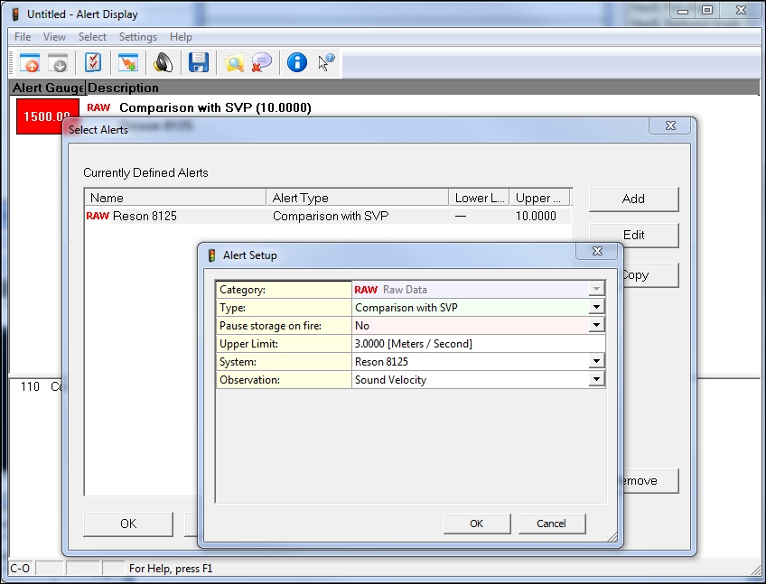
-
Filtering
When online, select the "Echosounder Settings" option from the "Settings" menu in the Controller to define the online blocking and filtering of the multibeam echosounder data.
Online and Replay offer the user to filter the data for the Reson Brightness en Colinearity tests.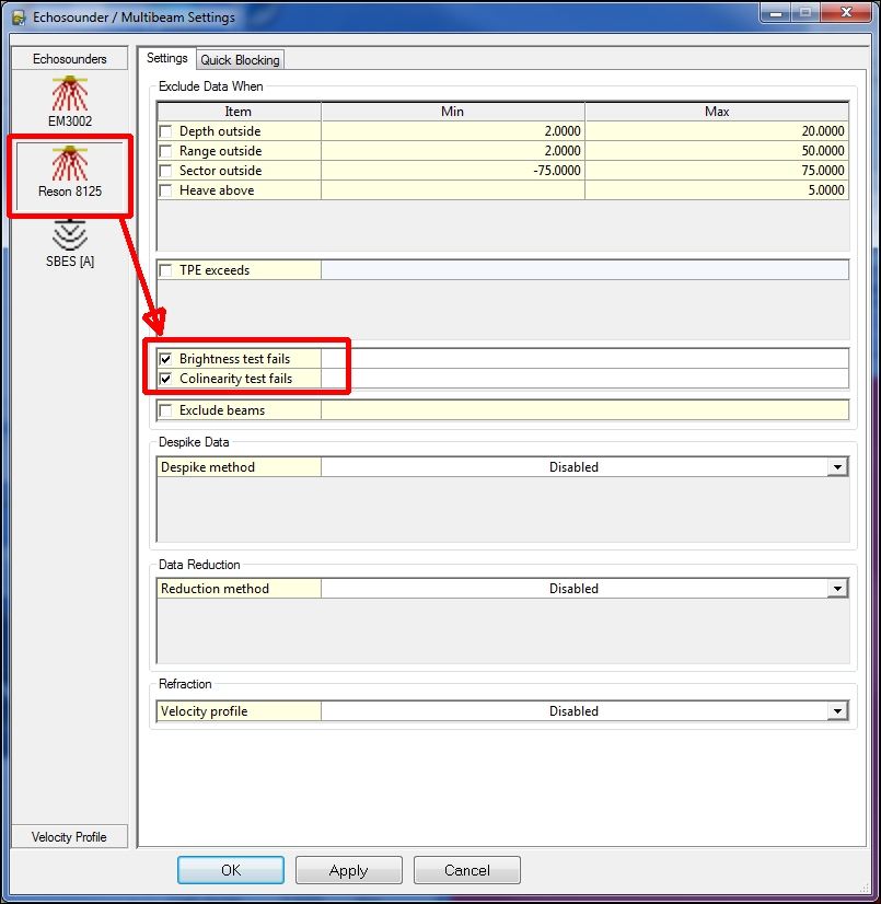
-
Multibeam Displays
-
Raw Multibeam Display to show raw data per multibeam system. One system per display
-
Swath System Display to show the motion and SV corrected scans. The display can show multiple MBES systems in one display.
-
-
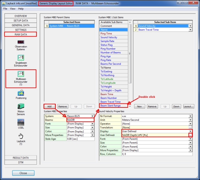
Generic Layout Display
It is possible to show the depth for NADIR beam, or with other words to show the depth below the transducer corrected for roll.