
Description
This driver interfaces to The Raytheon Applied Signal Technology (website) PROSAS Synthetic Aperture Sonar (SAS).
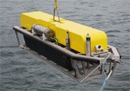
This sonar can deliver very high resolution images over long ranges thanks to the SAS processing techniques. The sonar transducer configuration is such that multiple (in this case 7) unique beams can be formed, hence this system could be classified as a "multibeam sidescan". The Sonar can also determine the arriving angle of each sample with interferometric techniques.
The PROSAS system consists of an underwater hardware component and a topside computer which runs the PROSAS software. Qinsy will be installed on a separate computer that interfaces via the network to the PROSAS topside computer. The PROSAS software will act as a TCP server to which the Qinsy driver will connect automatically and start asking for data. This driver will not be used to control the sonar, instead it should be controlled from the PROSAS software.
This driver can be used to decode various data types from the PROSAS: Sidescan/SAS, Bathymetry, Gyro, Position, Pitch/Roll, Altitude/Depth. Some data types are output in a delayed fashion due to the requirement of SAS processing that a sufficient number of pings are buffered before a frame can be processed. Ssee below for more information on the nature of the data. Note that the Sidescan/SAS contains multiple (7) scan lines per ping, for each beam one line.

Driver Information
|
Driver |
Raytheon AST PROSAS |
Interface Type |
TCP |
Driver Class Type |
TCP Client |
|---|---|---|---|---|---|
|
Yes |
Input / Output |
Input |
Executable |
DrvASTProSas.exe |
|
|
Related Systems |
|
||||
|
Related Pages |
|
||||
Decoding Notes
If a working PPS/Time Synchronization System is interfaced into the Template Database then the time tags from the messages are used, else the arrival time is used. It is assumed that the reported time tags are all in UTC.
Sidescan Sonar
Each sidescan sample is hardcoded converted from a 4 bytes floating point to an integer value of 0-65535 by a multiplication of 500.
For each ping 7 lines (24 for SAS) will be stored in the data container. The "frame overlap" bit is used to set the show/hide flag of the line. If the overlap bit is set then the line is assumed to be a hidden line. All ranges as reported by the sonar are assumed to be slant ranges in meters. The decoded sound velocity is used. All the lines have the same ping time. The line counter is used as the ping number.
Multibeam
Each side (port/starboard) will be treated as a separate multibeam system. Each sample is considered to be a beam, however only valid angles/samples will be decoded, samples that are marked as invalid will be ignored. The travel time is determined from the index of the sample, the beam angle is reported in the message per beam and is corrected by the driver for the transducer depression. The Sound velocity is decoded from the embedded SVP packet. It is assumed that this velocity was used to determine the beam angles with. The intensity of the beam is not filled in.
Positioning
Only latitude/longitude are filled in, height is always zero.
Pitch/Roll/Heave
Heave is zero and invalid.
Depth/Altitude
In meters.
Note: No Quality Indication is available.
Interfacing Notes
The PROSAS topside computer should be connected to the Qinsy PC through the network Ethernet port. Make sure that IP addresses and mask are set correctly on each computer in the network.
The PROSAS software should be setup to output SIDESCAN_IMAGE, SAS_IMAGE and BATHY_DOA Messages.
Database Setup
Object Definition
If both real-time and delayed post-processed data is to be visualized in Qinsy then it is suggested to create two objects to represent the PROSAS vehicle: a real-time and a delayed object. The real-time object can then be combined with other objects (e.g. the towing vessel, USBL) while the delayed object will be calculated on its own. Obviously all the sensors on the real-time object will have to decode the real-time data by selecting the proper slot (see below). The delayed object will contain, beside the obvious delayed sensors, the multibeam systems as this data is only available in a delayed fashion.
Node definition
The sonar systems usually consists of two transducers mounted on a tow fish some meters apart. Define two nodes that represent the Acoustic centers of the both transducers. Furthermore create a node exactly in between the created transducer nodes. This node is the location that every decoded position/altitude/depth refers to and hence will need to be selected for the respective system/observations.
System Definition
In General you can choose whether to decode the "real-time" sidescan/position/gyro/pitch/roll/depth/altitude data or the post-processed and hence delayed sas/multibeam/position/gyro/pitch/roll/depth/altitude data depending on the slot number that was selected for each observation. The multibeam data is only available as post-processed data.
Sidescan
Add a new system, select type "Sidescan Sonar" and set the driver, "Raytheon AST PROSAS". The IP Address of the PROSAS computer should be entered here. The port number should also be set, check PROSAS software to find out on what port number it listens on.
Note that it is currently not possible to decode two sidescan systems at the same time by the driver.
On the next pages of the wizard add two channels, the first port, the second starboard. The Node should be set to the respective transducer. The Number of beams should be set to 7 (or 24 for SAS, slot 2) for each channel. The slot number will determine if the SIDESCAN_IMAGE (slot = 1) or the SAS_IMAGE (slot = 2) is decoded.
Multibeam
Add two systems, one for each side, port/starboard. For the port side system select driver "Raytheon AST PROSAS Port Head", for starboard side the driver "Raytheon AST PROSAS Starboard Head". IP and port number should be identical to the Sidescan driver.
Transducer setup should be set to "Assume Common Acoustic Center". Select the proper transducer node. The Roll/Pitch/Heading offsets should typically be close to zero because the depression angle of the transducer was already accounted for in the driver. The Number of beams is important, this should be set to 20000 at least for the 1500 m range system.
Position Navigation system
Add a new system, select Driver, IP and port number identical to the sidescan driver. As the antenna node select the center node between the two transducer nodes. For the receiver number enter 10 if you want to decode the real time position from the SIDESCAN_IMAGE message and 20 if you would like to decode the delayed BATHY_DOA positions.
Gyro
Add a new system, select Driver, IP and port number identical to the sidescan driver. The slot determines what data is decoded. Choose slot SSS_HDG if you want to decode the real time position from the SIDESCAN_IMAGE message and slot MBE_HDG if you would like to decode the delayed BATHY_DOA positions.
Pitch Roll Heave Sensor
Add a new system, select Driver, IP and port number identical to the sidescan driver. The slot determines what data is decoded. Choose slot SSS_MRU if you want to decode the real time pitch and roll from the SIDESCAN_IMAGE message and slot MBE_MRU if you would like to decode the delayed BATHY_DOA pitch and roll values.
Underwater Sensor
Add a new system, select Driver, IP and port number identical to the sidescan driver. Add observations ROV Depth and ROV altitude, node should be the reference node between the transducer nodes again as mentioned above. Again, the slot determines what data is decoded. Choose slots SSS_DPT (ROV Depth) and SSS_ALT (ROV Altitude) when you want to decode the real time pitch and roll from the SIDESCAN_IMAGE message and slots MBE_DPT and MBE_ALT if you would like to decode the delayed BATHY_DOA pitch and roll values. Units should be set to meters.
For all auxiliary sensor observations (position, gyro, pitch/roll, altitude, depth) it is possible to decoded both the delayed as well as the real-time sensor data in a single template.
Slot number overview
|
|
|
|
|
|---|---|---|---|
|
Observation |
Observation |
post-processed/delayed slot |
remarks |
|
Sidescan |
1 |
2 |
1 = Multibeam Sidescan 2 = SAS Imagery |
|
Multibeam |
-- |
Not used |
only post-processed |
|
Position |
10 |
20 |
|
|
Gyro |
SSS_HDG |
MBE_HDG |
|
|
Pitch/Roll |
SSS_MRU |
MBE_MRU |
|
|
ROV Depth |
SSS_DPT |
MBE_DPT |
|